DOI:
10.1039/C2RA20159C
(Paper)
RSC Adv., 2012,
2, 5717-5728
Effect of residual stresses in injection molded cyclic olefin copolymer during microfabrication: hot embossing as well as thermal bonding
Received
26th January 2012
, Accepted 16th April 2012
First published on 18th April 2012
Abstract
Microfabrication using replication techniques such as hot embossing and injection molding followed by thermal sealing with a cover plate have been widely used in the large scale manufacturing of polymer based micro-devices for bio and chemical-MEMS (Micro Electro Mechanical Systems) applications. While several parameters are known to affect the integrity of microchannel replication, they have not been characterized and studied. These parameters include the influence of (i) in built residual stresses in substrate materials, made by injection molding, on replication fidelity during microfabrication using the hot embossing technique, (ii) sealing of injection molded microchips during thermal bonding and (iii) replication fidelity of annealed and unannealed substrates during hot embossing. This is the focus of the current work. Residual stresses were analysed using a grey-field polariscope and the fidelity of microreplication was characterized using a PLμ confocal microscope and a scanning electron microscope. It was found that the significant variation in replication fidelity of the injection molded substrate correlated well with the observed differences in the distribution of residual stresses. Good replication was obtained in regions with low residual stresses. The annealed substrate which had a low residual stress state with little chain orientation exhibited no variation in replication fidelity both along and across the flow direction of the injection molded substrate. Furthermore, the microchannels in the unannealed injection molding substrate exhibited significant distortion and deformation during subsequent thermal bonding.
1. Introduction
Fabrication of microfluidic devices for biological and chemical analysis has received significant interest in recent years. Examples of bioassays and biological procedures that have been miniaturized into a chip format include DNA sequencing, polymerase chain reaction (PCR), electrophoresis, DNA separation, enzymatic assays, immunoassays, cell counting, cell sorting, and cell culture; and for chemical analysis include microspectrophotometers, mass spectrometers, electrochemical detectors, chromatographs etc.1–8 Recently, many polymer-based microfabricated devices such as poly(methyl methacrylate) (PMMA), PDMS, poly(cyclic olefin) (PCO or COC), polycarbonate (PC), poly(tetrafluoroethylene) (PTFE), polystyrene (PS) and others9–14 have been explored for bio- and chemical-MEMS applications compared to conventional silicon and glass-based devices. The main advantages of polymer-based systems are the good material compatibility with chemical and biochemical assays, low cost and disposability.
A variety of methods exist for the fabrication of polymer-based microfluidic devices such as hot embossing,15 injection molding,16 laser ablation,17 and casting.18 Out of all these techniques hot embossing as well as injection molding are heavily used for mass production. Both microinjection molding and the hot embossing process have been investigated in the last few years for the fabrication of micro- and nano-structured devices.19 For microinjection molding, Zhao et al.20 have investigated the part quality by varying the injection molding process parameters. They found that metering size and holding pressure time are the process parameters which affect the part quality most significantly. A more recent study by Chen et al.,21 found that the mold temperature and packing pressure also affect the molding accuracy significantly. R. D Chen22 has also investigated the replication fidelity of microinjection molded devices. He found that the accuracies of the imprint width and depth increase with increasing mold temperature, melt temperature, injection velocity and packing pressure within a regular processing window. After microfabrication, it is necessary to seal the microdevices with a cover plate using the thermal bonding technique to facilitate fluid flow. However, according to our knowledge no one has studied the integrity of injection molded microdevices during thermal bonding. This is important because microfabrication using injection molding is a cyclic process and proceeds through different stages such as filling, packing, cooling and ejection, along with pressure and temperature variations. Residual stresses are generally developed in an injection molded part and caused by a number of reasons, including flow-induced residual stresses generated as a result of shear and extensional flows during processing,23,24 packing stresses resulting from the high pressure imposed during packing and thermal stresses formed during solidification and cooling.25–29 The residual stress distribution in a molded part is one of the major causes of viscoelastic deformation when the part is exposed above the glass transition temperature of the material.30 With the aid of optical measurements, the state of an injection-molded amorphous polymer can be quantified with high resolution in terms of its molecular orientation, residual stresses and density distributions. Measurement of anisotropic birefringence in a sample is a convenient method for determining the through-thickness internal stress distribution in polymer sheets. Thus, the focus of the present work is to characterize the residual stress state in injection molded microdevices and to assess how these residual stresses affect the integrity of such devices during thermal bonding.
With regard to hot embossing processes, Juang et al.31 have studied the flow pattern of polymer during hot embossing under both isothermal and non-isothermal conditions. Their results showed that the deformation patterns of the polymer film under these two conditions are substantially different. Yang and co-workers reported an innovative method for hot embossing by applying gas pressure directly to press the mold and the substrate.32 This may improve replication accuracy because more uniform embossing pressure was applied across the entire substrate. Becker and Hein also presented some suggestions for improving processing conditions for the hot embossing of polymer parts with microsized features.33 The suggestions include the recommendation that (i) the thermal variation should be limited to between 25 and 40 °C to minimize thermally induced stresses, and that (ii) the embossing pressure must be around 5–20 MPa. Laurence et al. indicated that the quality of micrometric pattern replication by hot embossing lithography (HEL) strongly depends on the size of the mold features.34 However, another important aspect which has been overlooked during hot embossing is the effect of stresses inside the substrate materials on replication fidelity. Injection molding is not only used for fabricating products with complex geometry for microfabrication but is also used for molding flat sheets of different sizes and thicknesses for different applications including substrate materials for hot embossing and cover plates for thermal lamination. As a result residual stresses exist in the substrate material and these stresses cause significant viscoelastic deformation in the microfeatures during hot-embossing at above the glass transition temperature of the material. Hence, we have investigated the effect of residual stresses on replication fidelity of injection molded substrates during hot-embossing. Although microinjection molding and hot embossing have been used in microfabrication for several years, the influence of residual stresses either in injection molded substrate materials or in injection molded microdevices during device fabrication have not yet been investigated systematically.
In the present study, the effect of residual stresses in injection molded COC substrates on a micro-hot-embossing process was established by comparing the replication fidelity of COC substrates at different locations throughout the embossed substrate. Next, the influence of annealing of the substrate material on replication fidelity during hot-embossing was also investigated. Finally, the effect of residual stresses in an injection molded microfeature substrate on channel integrity during thermal bonding was studied and compared with that observed using a hot embossed substrate.
Based on the findings, it is shown that high replication fidelity can be obtained when an understanding of the effect of residual stresses in the polymer substrate is coupled with optimization of the embossing temperature, embossing pressure and embossing time. Furthermore, such knowledge can provide a basis for the production of high fidelity COC microfluidic devices.
2. Experimental details
2.1. Materials
In this study, Topas (8007 grade) COC provided by TICONA, Japan, was used. It is a glassy polymer at room temperature, with a glass transition temperature of 78 °C. Rectangular Topas samples of 1 mm, 25 mm and 75 mm in thickness, width and length respectively were molded using an injection molding machine (Battenfeld HM 25/60), Austria. The initial melt temperature and the mold temperature were 190 °C and 90 °C respectively. Other molding parameters such as injection speed, holding pressure, injection pressure were optimized for part quality and cycle time. The injection parameters used are shown in Table 1. A fan gate was employed (see Fig. 1a), such that a simple uni-directional flow pattern could be achieved during the filling phase to minimize warpage. Substrates measuring 25 mm × 25 mm used for embossing were cut from the mid-section of the molded specimens.
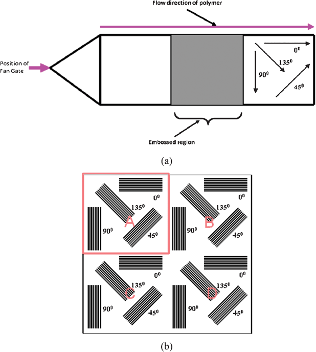 |
| | Fig. 1 Schematic diagrams of (a) injection molded specimen and (b) embossing die | |
| Parameter |
Values |
| Nozzle temperature |
190 °C |
| Holding pressure |
60 × 106 Pa |
| Injection pressure |
120 × 106 Pa |
| Back pressure |
2.5 × 10⁶ Pa |
| Injection speed |
100 mm s−1 |
| Cooling time |
60 s |
| Mold temperature |
90 °C |
2.2. Fabrication of micro-embossing die
Photolithographic techniques were used to fabricate a 500 μm thick Si-based die measuring 20 mm by 20 mm. The microfeatures of the die include an array of channels that were 20 μm deep and 50 μm wide with a pitch size of 150 μm. The die is divided into four parts named as A, B, C, and D (see Fig. 1b). Part A contain four sets of microchannels (with each set containing an array of 8 microchannels) having different orientations such as 0, 45, 90, 135°. The other parts B, C and D have the same structure as in A. Such a mold allows the determination of the replication fidelity at different locations and assessment of whether replication is uniform throughout the substrate. The use of microchannels with different orientations enables the assessment of the replication fidelity along and across the flow directions of the injection molded substrate.
To fabricate the die, the channels were first drawn using the standard L-EDIT software. The image of the drawn channels was printed onto a transparency with high resolution. Separately, a 10 μm thick AZ 9260 positive photoresist was deposited on the surface of a silicon wafer with crystal orientation <100>, and soft baked at 100 °C for 4 min on a hot plate. Subsequently, the transparency was placed on top of the silicon wafer. Upon exposure to a UV light source, the photoresist was developed, revealing the transferred image. This was followed by a deep reactive ion etching (DRIE) process to create a channel depth of approximately 25 μm in the silicon wafer. The height and the width of the positive image were controlled by the etching time. To further reduce the friction coefficient of the sidewall surfaces of the die, the silicon die was plasma treated with C4F8 gas for 2 min to create a thin layer of teflon-like material on the sidewall surfaces (post-passivation). This facilitates demolding of the embossed substrate.
2.3. Residual stress measurement using a grey-field polariscope
Generally, residual stress produces proportional double refractive indices or birefringence in transparent materials such as glass and polymers. The grey-field polariscope is an important instrument for the visualization and rapid measurement of whole-field residual stress distribution in samples. Fig. 2 shows a schematic diagram of a grey-field polariscope. The grey-field polariscope uses a polarizer and a quarter wave plate to illuminate transparent samples with circularly polarized light. After traversing through birefringent material that is subject to residual stress, circularly polarized light transforms into elliptically polarized light which can then be analyzed through a rotating analyzer placed before the charge coupling device (CCD) camera. As the analyzer rotates, the intensity of the transmitted light is at a maximum when the polarization axis of the analyzer matches with that of the major axis of the polarization ellipse and is at a minimum when the polarization axis of the analyzer matches the minor axis of the polarization ellipse. Thus, the intensity of transmitted light is dependent on the analyzer angular position α and is given by,| | | I = a2[1 + sin2(α − β)sinΔ] | (1) |
| |  | (2) |
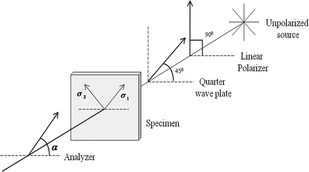 |
| | Fig. 2 Schematic diagram of a grey-field polariscope (the fast axis of the quarter waveplate is oriented at 45° to the polarization axis of the polarizer to form circularly polarized light) | |
Where, a is the amplitude of transmitted light, β is the orientation of the fast axis and Δ is the phase retardation produced between the major and minor axis of circularly polarized light due to stress-birefringent material. Eqn (2) represents the expression for phase retardation which directly depends on the difference between the first (σ1) and second (σ2) principal stresses, stress optic coefficient (C) of the material and thickness of material (d). If the stress-birefringent material has no effect on the incident polarization (sinΔ = 0), the transmitted light will be circularly polarized light.35 Now, eqn (1) can be re-written in terms of modulation frequency (sin2α and cos2α) as,
| | | I = Ia + Icαcos2α + Isαsin2α | (3) |
Where, Icα = −(s)sin2β, Isα = (s)cos2β, s = a2sinΔ and Ia is the average light collected by CCD camera. In order to calculate important parameter such as β and Δ, four phase shifted intensity images I1, I2, I3 and I4 are recorded using a CCD camera with analyzer orientations of 0°, 45°, 90° and 135° respectively and are given by,
Using eqn (4), (5), (6) and (7), these phase shifted intensity images are further processed as follows to calculate the required parameters,36
| |  | (8) |
| |  | (10) |
Eqn (9) and (10) give the measurement for phase retardation and orientation of the fast axis due to stress-birefringent material respectively. In our experiment, we have used an LED source at a green wavelength λ = 540 nm to illuminate the Topas (8007 grade) sample. All the samples were tested by recording the phase shifted intensity images using a grey-field polariscope and then processed to determine the phase retardation and orientation of the fast axis.
2.4. Hot embossing and thermal bonding equipment
The machine (Atlas™ Series Heated Platens P/N 15![[thin space (1/6-em)]](https://www.rsc.org/images/entities/char_2009.gif) 515, SPECAC LTD, USA) employed for both hot embossing as well as thermal bonding consisted of a bench top hydraulic press with a load capacity of 15 tons. It was fitted with two 100 mm diameter heated ú (top and bottom). Cooling of the platens was achieved by chilled water and natural air convection. The temperatures of both platens were measured and controlled by a temperature controller through thermocouples embedded in them. The embossing force employed via the platens in the current study was 0.35 ton which translated into an embossing load of 3.43 kN.
515, SPECAC LTD, USA) employed for both hot embossing as well as thermal bonding consisted of a bench top hydraulic press with a load capacity of 15 tons. It was fitted with two 100 mm diameter heated ú (top and bottom). Cooling of the platens was achieved by chilled water and natural air convection. The temperatures of both platens were measured and controlled by a temperature controller through thermocouples embedded in them. The embossing force employed via the platens in the current study was 0.35 ton which translated into an embossing load of 3.43 kN.
2.5. Thermal analysis
The glass transition temperature of Topas COC was determined using a Perkin-Elmer DSC7 differential scanning calorimeter. The sample was heated from 30 to 120 °C at a heating rate of 20 °C min−1 with purged dry nitrogen gas at 20 mL min−1. Tg was determined to be 78 °C (average of three runs) which matches that provided by the Topas 8007 datasheet.
2.6. Characterization of microchannels using a confocal microscope and a scanning electron microscope
The 3D topography and profile of the embossed microchannels were measured using a polarized light micro (PLμ) confocal microscope. Surface images were obtained using a scanning electron microscope (SEM). Although an indication could be provided by observing the surface view using SEM or the PLμ topography (3D image) of the replicated embossed structure of the silicon die, a proper assessment could only be made by comparing the key feature of the embossed structure with the die. This also allows the optimization of the process parameters.
The key feature is the channel cross-sectional profile as this provides the appropriate measure of replication fidelity as it reflects the overall scenario of polymer flow inside the cavity of the mold. Thus, in this study, both surface topography and channel profile were used to assess the replication quality.
3. Results and discussion
3.1. Effect of residual stress on replication
To study the effect of residual stresses in injection molded substrates on replication fidelity, 1 mm thick injection molded Topas-8007 (Tg = 78 °C) substrates were embossed at four different embossing temperatures such as 85, 90 and 95 and 100 °C while keeping the load at 3.43 kN and the holding time of 300 s constant. At 85 °C, significant variation in replication fidelity (i.e. surface morphology as well as the cross-section profile of microchannels) was observed at different locations on the embossed substrate such as the 90° aligned microchannel in part A and C with the 90° aligned microchannel in part B and D (see Fig. 3 and 4). However, with an increase in temperature the variation in replication fidelity decreases and above 95 °C all the microchannels at different locations replicate perfectly throughout the substrate. This can be accounted as follows. At lower hot embossing temperatures the variation in replication fidelity at different locations could be due to the differences in residual stresses inside the injection molded substrates used for embossing and stress relief occurs during the embossing process. At higher embossing temperatures, the stresses might get released effectively within the embossing time period such that little or no variation in replication fidelity was observed.
![Typical cross sectional channel profile of 90° alignment microchannel in (a) Part A, (b) Part B, (c) Part C and (d) Part D of 1 mm thick Topas substrate. [Embossing T = 85 °C, embossing load = 3.43 kN and holding time = 300 s]](/image/article/2012/RA/c2ra20159c/c2ra20159c-f3.gif) |
| | Fig. 3 Typical cross sectional channel profile of 90° alignment microchannel in (a) Part A, (b) Part B, (c) Part C and (d) Part D of 1 mm thick Topas substrate. [Embossing T = 85 °C, embossing load = 3.43 kN and holding time = 300 s] | |
![Typical SEM images of replicated microchannel (a) Part A, 90° alignment and (b) Part B, 90° allignment on Topas substrate. [Embossing T = 85 °C, embossing load = 3.43 kN and holding time = 300 s]](/image/article/2012/RA/c2ra20159c/c2ra20159c-f4.gif) |
| | Fig. 4 Typical SEM images of replicated microchannel (a) Part A, 90° alignment and (b) Part B, 90° allignment on Topas substrate. [Embossing T = 85 °C, embossing load = 3.43 kN and holding time = 300 s] | |
To validate the above, the residual stresses in the injection molded substrate were measured before they were embossed by recording phase shifted intensity images using the grey-field polariscope (see Fig. 5a). These four phase shifted images were processed to evaluate the orientation of the fast axis and phase retardation in the sample. Fig. 5a shows the two-dimensional map of the orientation of the fast axis throughout the embossed region. The orientation of the fast axis is around 53° within this sample which suggests that the direction of the first principal stress is not in the direction of the injection molding. Therefore, it is difficult to calculate the residual stresses quantitatively inside the sample and we considered residual stresses† in terms of phase retardation throughout the whole experimental analysis. Fig. 5b shows the two-dimensional map for phase retardation throughout the embossed region. From the figure, it is clear that there is significant variation in phase retardation throughout the embossed region and it varies from one end to the other end of the substrate along the flow direction of the polymer resulting in differences in replication fidelity at the different locations. This variation in phase retardation inside the substrate mainly depends on the injection processing parameters as well as the difference in flow behavior during mold filling and the thermal stresses induced during solidification and cooling during injection molding. In the flow direction, the polymer stretched more due to shearing compared to across the flow direction which also helps to introduce more stresses in the flow direction. This experimental observation using the grey-field polariscope clearly matches our expectation that the differences in residual stresses inside the injection molded substrate affect the variation in replication fidelity at different locations for embossing at lower temperatures. However at higher embossing temperatures (greater than 95 °C), good replication fidelity throughout the substrate was observed.
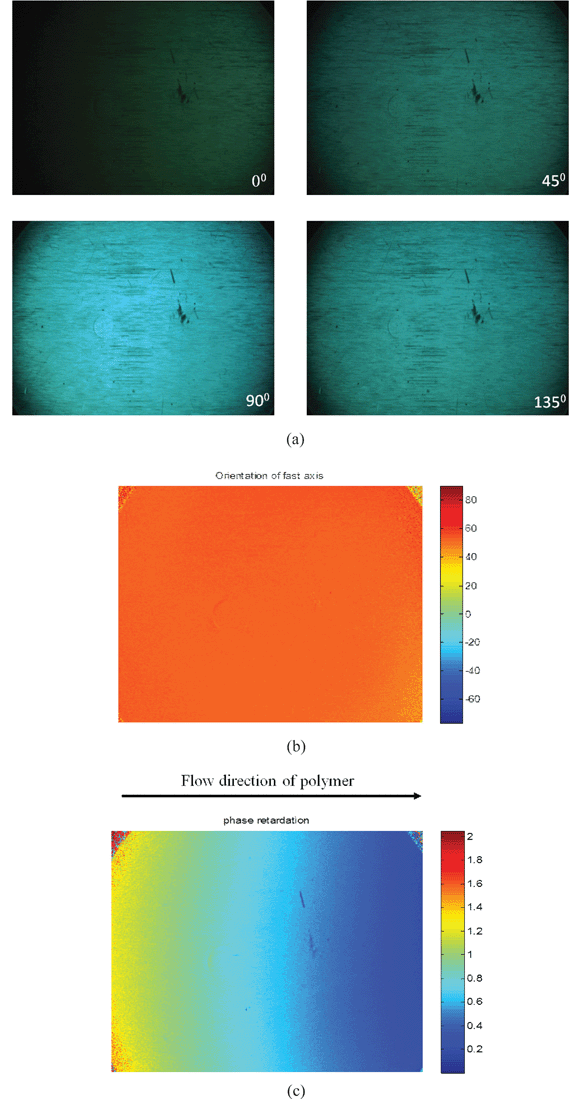 |
| | Fig. 5 (a) Four phase shifted images recorded at different analyzer positions, (b) orientation of fast axis and (c) phase retardation measured from phase shifted images using a grey-field polariscope for injection molded 1 mm thick Topas-8007 substrate. | |
Next the effect of residual stresses on replication fidelity of microchannels aligned along and across the flow direction of the polymer (e.g., part B 90° with part D 0° in Fig. 1b) in the injection molded substrate was examined. Fig. 6 shows the replication fidelity of microchannels along and across the flow direction of the polymer at 80 °C with an embossing load of 3.43 kN and a holding time of 300 s. From the figure it is clear that along the flow direction of the polymer, replication fidelity is much better than across the flow direction. This indicates that the variation in replication fidelity in injection molded substrate not only depends on residual stresses but also on the molecular chain alignment. For 45° and 135° alignment of the microchannel the replication fidelity is in between that observed for the 0° and 90° aligned microchannels.
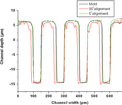 |
| | Fig. 6 Cross sectional channel profile of replicated microstructure along (0° alignment) and across (90° alignment) the flow direction of the polymer on the Topas substrate. | |
As the polymer chains are aligned along the flow direction of the polymer, it is easier to replicate along this direction in comparison to across the flow direction. However, with an increase in temperature the variation in replication fidelity along and across the flow direction reduces and at 95 °C with an embossing load of 3.43 kN and holding time of 300 s, no variation in replication fidelity was observed both along and across the flow direction. The reason could be due to the annealing of the substrate material at this temperature which enables the chains aligned along the flow direction to become relaxed and isotropic so that good replication could be obtained across the flow direction.
From the above, it is clear that injection molding induces residual stresses inside the polymer substrate. One way to release the residual stresses is by annealing. To study the effect of annealing on replication fidelity, the injection molded substrate before embossing was annealed at 90 °C for two hours in an oven. Then a hot embossing experiment was performed on both the annealed and un-annealed substrate at 80 °C with an embossing load of 3.43 kN and holding time of 300 s. Fig. 7 shows the replication fidelity of annealed and un-annealed substrate along and across the flow direction of the polymer. From Fig. 7a it is clear that there is no difference in replication fidelity between annealed and un-annealed substrate of the microchannels replicated along the flow direction of polymer. However, significant variation in replication fidelity was observed for microchannels replicated across the flow direction of polymer (see Fig. 7b). The annealed substrate replicated perfectly the mold features, whereas the un-annealed substrate showed incomplete filling of the mold cavities.
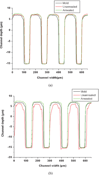 |
| | Fig. 7 Cross sectional channel profile of un-annealed and annealed Topas-8007 substrate after embossing (a) along and (b) across the flow direction of polymer. | |
In order to find out the variation in replication fidelity in annealed and un-annealed substrate, residual stresses inside both the substrate were measured using a polariscope before performing hot embossing experiments. Fig. 8a shows four phase shifted images recorded for an annealed sample. It can be clearly seen that the intensity of the recorded images is not changed at four distinct positions of the analyzer which means that incident circularly polarized light remains the same after passing through an annealed sample (i.e. Δ = 0). Fig. 8b shows a two-dimensional plot of the orientation of the fast axis and Fig. 8c shows the zero phase retardation measured for an annealed sample. However in the case of the un-annealed sample a significant change in intensity was observed (see Fig. 5). It is evident from the phase shifted images that incident circularly polarized light changes to elliptically polarized light due to phase lag (or residual stress) present in an un-annealed sample. This experimental observation clearly matches with the theoretical prediction that after annealing no residual stresses are left inside the injection molded substrate as a result good replication fidelity was observed for annealed samples.
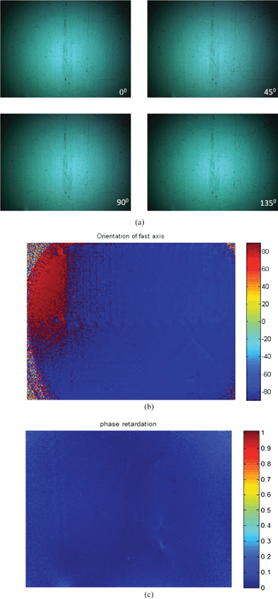 |
| | Fig. 8 (a) Phase shifted images at different analyzer positions, (b) orientation of fast axis and (c) phase retardation measured from phase shifted images using a grey-field polariscope for annealed Topas-8007 substrate. | |
3.3. Effect of residual stresses during thermal bonding of hot embossed and injection molding micromixture
Next, thermal bonding of a cover plate to both the hot embossed and injection molding micromixer plate was carried out and the change in profile of the microchannel after bonding was determined. A schematic diagram of the micromixer is shown in Fig. 9. In this series of bonding experiments, a glass slide was used as the cover plate so that it could be removed after the bonding process and the integrity of the channels in the micromixer plate could be assessed. The bonding experiments were performed using a hydraulic press (Specac) at a temperature range of Tg − 10 to Tg + 15 °C with a minimum load of around 100 N for 1 min holding time. Fig. 10 represents the channel topography of both the injection molded and hot embossed micromixer at position C after separating the bonded micromixer plate from the cover glass slide. From the figure it is evident that no deformation in the microchannel took place for both injection and hot embossed micromixer when thermal bonding was performed below Tg. However, the microchannels in the injection molding micromixer plate started to deform when the bonding temperature was above Tg (i.e., at Tg +5 °C onwards), while the hot embossed micromixer maintained its channel integrity even after bonding at 10 °C above Tg. This may be due to the existence of residual stresses inside the micromixer plate made by the injection molding technique.
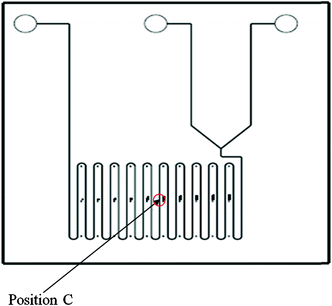 |
| | Fig. 9 Schematic diagram of micromixer. | |
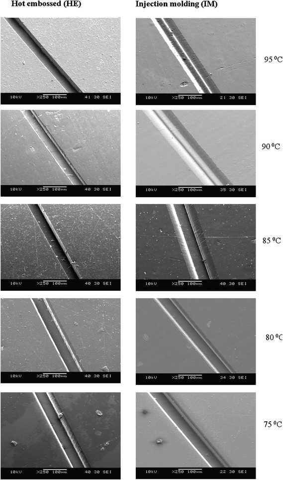 |
| | Fig. 10 Typical SEM images of deformed microchannel in the micromixer plate of an injection molded and hot embossed micromixer during thermal bonding at different temperatures on Topas-8007 (Tg = 78 °C). | |
In order to confirm the effect of residual stresses during thermal bonding both injection molded and hot embossed micromixer plates were examined using a grey-field polariscope. Fig. 11 and 12 show the phase shift and phase retardation images of hot embossed and injection molded micromixer plates respectively. From the figures it is clear that significant residual stresses existed in the injection molding micromixer. Thus, during thermal bonding the residual stresses were released leading to distortion in the microchannel profile and dimensions. However, in the case of the hot embossed micromixer, no variation in phase shift was observed and the phase retardation value was very low indicating zero residual stresses. Although the hot embossed micromixer plate was made from injection molded substrate; the reason for maintaining the channel integrity during thermal bonding above Tg is due to the fact that during hot embossing the injection molded substrate releases the residual stresses as the experiment was done at 100 °C with the embossing load of 2.94 kN to obtain perfectly replicated microfeatures. This further confirms that the residual stresses in injection molded microdevices also affect the microchannel integrity during thermal bonding.
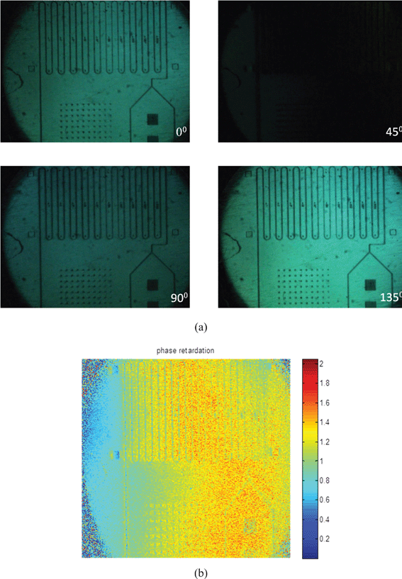 |
| | Fig. 11 Typical (a) phase shifted and (b) phase retardation images of injection molded micromixer using a grey-field polariscope at different analyzer positions. | |
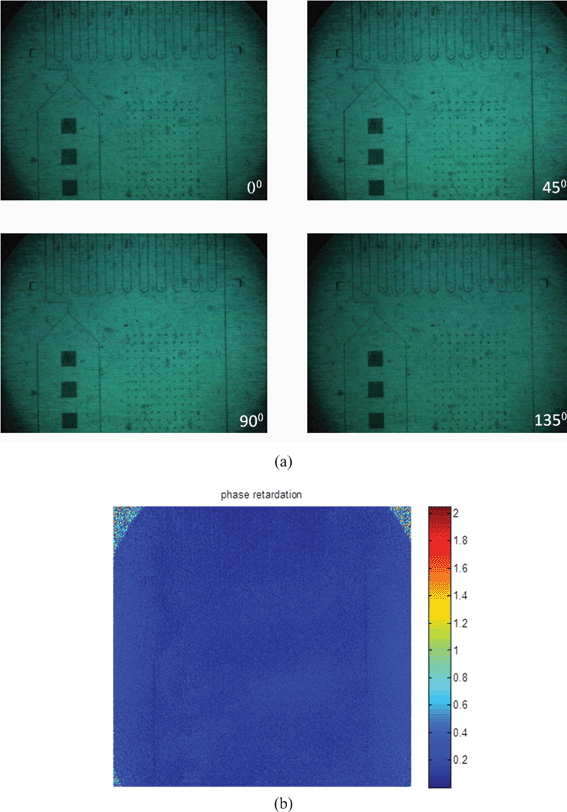 |
| | Fig. 12 Typical (a) phase shifted and (b) phase retardation images of hot embossed micromixer using a grey-field polariscope at different analyzer positions. | |
4. Conclusions
We have demonstrated the effect of residual stresses in injection molded substrates during hot embossing as well as thermal bonding. Based on the findings, it is shown that high replication fidelity can be obtained when an understanding of the effect of residual stresses in the injection molded polymer substrate is fully characterized. Annealing is the best way to reduce the residual stresses in injection molded substrates and results in good replication fidelity during hot embossing. During thermal bonding above Tg, it is necessary to use the hot embossed microfeature rather than the injection molded microfeature for high bond strength applications.
References
- E. W. K. Young, E. Berthier, D. J. Guckenberger, E. Sackmann, C. Lamers, I. Meyvantsson, A. Huttenlocher and D. J. Beebe, Anal. Chem., 2011, 83, 1408–1417 CrossRef CAS.
- P. Zhou, L. Young and Z. Chen, Biomed. Microdevices, 2010, 12, 821–32 CrossRef.
- J. Do and C. H. Ahn, Lab Chip, 2008, 8, 542–549 RSC.
- M. Tanaka, T. Ooie, Y. Yamachoshi, T. Nakahara, M. Hino, R. Akamine and M. Kataoka, J. Laser Micro/Nanoeng., 2010, 5, 35–38 CrossRef CAS.
- E. Berthier, E. W. K. Young and D. J. Beebe, Lab Chip, 2012, 12, 1224–1237 RSC.
- Y. H. Chen and S. H. Chen, Electrophoresis, 2000, 21, 165–170 CrossRef CAS.
- M. Galloway, W. Stryjewski, A. Henry, S. M. Ford, S. Llopis, R. L. McCarley and S. A. Soper, Anal. Chem., 2002, 74, 2407–2415 CrossRef CAS.
- H. Yin, K. Killeen, R. Brennen, D. Sobek, M. Werlich and T. V. de Goor, Anal. Chem., 2005, 77, 527–533 CrossRef CAS.
- G. B. Lee, S. H. Chen, G. R. Huang, W. C. Sung and Y. H. Lin, Sens. Actuators, B, 2001, 75, 142–148 CrossRef.
- J. M. Li, C. Liu, H. C. Qiao, L. Y. Zhu, G. Chen and X. D. Dai, J. Micromech. Microeng., 2008, 18, 015008 CrossRef.
- G. V. Kaigala, S. Ho, R. Penterman and C. J. Backhouse, Lab Chip, 2007, 7, 384–387 RSC.
- Y. Liu, D. Ganser, A. Schneider, R. Liu, P. Grodzinski and N. Kroutchinina, Anal. Chem., 2001, 73, 4196–4201 CrossRef CAS.
- L. Yi, W. Xiaodong and Y. Fan, J. Mater. Process. Technol., 2008, 208, 63–69 CrossRef.
- D. A. Mair, E. Geiger, A. P. Pisano, J. M. J. Fréchet and F. Svec, Lab Chip, 2006, 6, 1346–1354 RSC.
- L. Martynova, L. E. Locascio, M. Gaitan, G. W. Kramer, R. G. Christensen and W. A. MacCrehan, Anal. Chem., 1997, 69, 4783–4789 CrossRef CAS.
- R. M. McCormick, R. J. Nelson, M. G. Alonso-Amigo, D. J. Benvegnu and H. H. Hooper, Anal. Chem., 1997, 69, 2626–2630 CrossRef CAS.
- J. C. McDonald and G. M. Whitesides, Acc. Chem. Res., 2002, 35, 491–499 CrossRef CAS.
- M. A. Roberts, J. S. Rossier, P. Bercier and H. Girault, Anal. Chem., 1997, 69, 2035–2042 CrossRef CAS.
- M. Heckele and W. K. Schomburg, J. Micromech. Microeng., 2004, 14, R1, DOI:10.1088/0960-1317/14/3/R01.
- J. Zhao, R. H. Mayes, G. Chen, H. Xie and P. S. Chan, Polym. Eng. Sci., 2003, 43, 1542–1554 CAS.
- S. C. Chen, J. A. Chang, Y. J. Chang and S. W. Chau, ANTEC, 2005, 61, 556–560 Search PubMed.
- R. D. Chien, Sens. Actuators, A, 2006, 128, 238–247 CrossRef.
- A.
I. Isayev and D. L. Crouthamel, Polym.-Plast. Technol. Eng., 1984, 22, 177 CrossRef CAS.
- B. Haworth, C. S. Hindle, G. J. Sandilands and J. R. White, Plast. Rubber Proc., 1982, 2, 59 CAS.
- A. Sen and M. Bhattacharya, Polymer, 2000, 41, 9177 CrossRef CAS.
-
T. A. Osswald and G. Menges, Materials Science of Polymers for Engineers, Hanser, 1996 Search PubMed.
- L. D. Coxon and J. R. White, Polym. Eng. Sci., 1980, 20, 230 CAS.
- J. H. Jung, S. W. Lee and J. R. Youn, Macromol. Symp., 1999, 148, 263 CrossRef CAS.
- S. C. Lee and J. R. Youn, J. Reinforc. Plast. Compos., 1999, 18, 186 CAS.
- X. Zhang, X. Cheng, K. A. Stelson, M. Bhattacharya, A. Sen and V. R. Voller, J. Thermal Stresses, 2002, 25, 523 CrossRef.
- Y. J. Juang, J. Lee and K. W. Koelling, Polym. Eng. Sci., 2002, 42, 539–550 CAS.
- J. H. Chang and S. Y. Yang, Microsyst. Technol., 2003, 10, 76–80 CrossRef CAS.
- H. Becker and U. Heim, Sens. Actuators, A, 2000, 83, 130–135 CrossRef.
- R. Laurence, M. Christel and P. P. Jean, Microelectron. Eng., 2004, 71, 272–276 CrossRef.
- G. Horn, J. Lesniak, T. Mackin and B. Boyce, Rev. Sci. Instrum., 2005, 76, 045108 CrossRef.
- A. Asundi, L. Tong and C. G. Boay, Appl. Opt., 1999, 38, 5931–5935 CrossRef CAS.
Footnote |
| † In this experiment it is difficult to measure the exact value of residual stresses at different directions of the injection mold substrate because the principal stress axis does not align along the flow direction of the polymer. Therefore, we considered residual stresses in terms of phase retardation throughout our explanation. |
|
| This journal is © The Royal Society of Chemistry 2012 |
Click here to see how this site uses Cookies. View our privacy policy here. 


![[thin space (1/6-em)]](https://www.rsc.org/images/entities/char_2009.gif) 515, SPECAC LTD, USA) employed for both hot embossing as well as thermal bonding consisted of a bench top hydraulic press with a load capacity of 15 tons. It was fitted with two 100 mm diameter heated ú (top and bottom). Cooling of the platens was achieved by chilled water and natural air convection. The temperatures of both platens were measured and controlled by a temperature controller through thermocouples embedded in them. The embossing force employed via the platens in the current study was 0.35 ton which translated into an embossing load of 3.43 kN.
515, SPECAC LTD, USA) employed for both hot embossing as well as thermal bonding consisted of a bench top hydraulic press with a load capacity of 15 tons. It was fitted with two 100 mm diameter heated ú (top and bottom). Cooling of the platens was achieved by chilled water and natural air convection. The temperatures of both platens were measured and controlled by a temperature controller through thermocouples embedded in them. The embossing force employed via the platens in the current study was 0.35 ton which translated into an embossing load of 3.43 kN.
![Typical cross sectional channel profile of 90° alignment microchannel in (a) Part A, (b) Part B, (c) Part C and (d) Part D of 1 mm thick Topas substrate. [Embossing T = 85 °C, embossing load = 3.43 kN and holding time = 300 s]](/image/article/2012/RA/c2ra20159c/c2ra20159c-f3.gif)
![Typical SEM images of replicated microchannel (a) Part A, 90° alignment and (b) Part B, 90° allignment on Topas substrate. [Embossing T = 85 °C, embossing load = 3.43 kN and holding time = 300 s]](/image/article/2012/RA/c2ra20159c/c2ra20159c-f4.gif)


