Facile approach to an advanced nanoporous silicon/carbon composite anode material for lithium ion batteries
Xuejiao
Feng
,
Jun
Yang
*,
Pengfei
Gao
,
Jiulin
Wang
and
Yanna
Nuli
School of Chemistry and Chemical Engineering, Shanghai Jiao Tong University, Shanghai 200240, China. E-mail: yangj723@sjtu.edu.cn (J. Yang); Fax: (+86)-21-54747667; Tel: (+86)-21-54747667
First published on 18th April 2012
Abstract
A new kind of nanoporous silicon/carbon composite with excellent electrochemical performance was prepared via a mechanochemical reaction between SiCl4 and Li13Si4 under ball milling. The whole process is mild and simple, using no corrosive acid. In particular, this method is suitable for large-scale synthesis of nanoporous silicon based composite for a potential anode material of lithium ion batteries. Different structures of silicon and carbon coating approaches were investigated. Compared with nano-Si/SP/C-D and np-Si/SP/C-S, the np-Si/SP/C-D exhibited a considerably high initial capacity of 1413.2 mAh g−1 and an excellent cycling stability with 91.1% capacity retention against at 2nd cycle after 100 cycles at a current density of 100 mA g−1. The superior electrochemical performance is attributed to the open nanoporous structure, which can accommodate the volume expansion, and the excellent electronic and ionic conductivity of a thin carbon layer.
Introduction
Lithium ion batteries are widely used in portable electronic devices.1–3 However, the commercialized graphite anode materials of lithium ion batteries with low theoretical capacity (372 mAh g−1) and poor rate capability cannot satisfy the demand of high performance lithium ion batteries.4,5 Finding a new electrode material, which substitutes for graphite materials, has been an urgent research problem.6 Silicon, owing to its high theoretical specific capacity (4200 mAh g−1, ca.Li4.4Si), is regarded as the most promising candidate for the anode material in lithium ion batteries.7,8 However, volume changes during cycling cause pulverization and capacity fade, which is an obstacle of the application of silicon as an anode.8–11Recently, close attention has focused on reducing such volume change via employing mixed-conducting carbon phase.12–15 Wu et al. proposed natural graphite coated by Si nanoparticles with better cycling performance16 and also used polyacrylonitrile as a carbon source for preparing core–shell nanocomposites, which presented higher apparent diffusion coefficients of lithium ions.17 Incorporation of CNT18 and graphene19 with silicon can enhance the cycle performance of lithium ion batteries via improving the electronic conductivity and suppressing the volume change of the Si active material. Various methods have been employed for preparing carbon coated silicon composite, i.e. pyrolysis,20 ball milling21 or chemical vapor deposition (CVD) methods.22 Non-uniform silicon distribution and the dense carbon configuration often lead to rapid capacity fade on cycling. From the viewpoint of a uniform carbon layer structure, the CVD method is suitable for covering carbon on silicon. However, the silicon particles modified with carbon via traditional methods have not resulted in a large breakthrough on electrode performance so far. Moreover, high-cost graphene is still far from industrial application level.23
On the other hand, porous structure was demonstrated as another effective means of accommodating the volume expansions/contractions.11,24–26 Porous structure can provide sufficient space to absorb the large volume expansions and thereby enhance the electrochemical performance of silicon.25 Kim et al. reported 3D porous bulk Si particles by thermally annealing and etching of physical composites obtained from butyl-capped Si gels and SiO2 at high temperature, which delivered a reversible capacity of 2800 mAh g−1 at a rate of 1C after 100 cycles.27 The cycling improvements benefited from its highly porous and interconnected structure. However, the synthetic process is too complicated and expensive. Wei et al. proposed a novel tandem structure of porous silicon film on single-walled carbon nanotube film.28 But the capacity decreased by 18% after 40 cycles. Yin et al. prepared silicon/carbon nanoporous microspheres by electrospray, but the capacity was decreased below 1000 mAh g−1 after 50 cycles.13 For industrial applications, both large-scale synthesis of the Si composites and excellent electrochemical performance are necessary.
Mechanochemical reaction offers an attractive route for the large-scale synthesis of composite materials. In this work, we design and obtain a new kind of nanoporous silicon/Super P (np-Si/SP) via a mechanochemical reaction between SiCl4 and Li13Si4 under ball milling. The whole process of preparing such np-Si/SP is mild and simple, using no corrosive acid. Furthermore, chemical vapor deposition (CVD), using cheap toluene as carbon source, was used to coat a thin carbon layer on the np-Si/SP particles for the formation of a stable SEI layer and uniform interfacial reaction.29 The np-Si/SP/C-D composite exhibited a reversible capacity 1240.8 mAh g−1 in the initial cycle and after 200 cycles it was still 982 mAh g−1 at a current density of 300 mA g−1. Our strategy provides a facile avenue for the large-scale synthesis of an excellent silicon based composite, which is promising for application in lithium ion batteries.
Experimental
Material preparation
2 ml SiCl4 (Aladdin-reagent Corp., China, 99.9% pure), 0.84 g Li13Si4 powder (SIMIT, CAS, China) and 0.10 g Super P carbon black (40 nm, Timical) were loaded in an 80 ml argon filled agate vial with 15 agate balls of 10 mm in diameter. The milling was performed on a Planetary Mono Mill P-6 (Fritsch, Germany) at a rotation speed of 450 rpm for 20 h. Then the as-milled product (Si/Super P/LiCl) was moved into a quartz tube and heated at the rate of 5 °C min−1 under a constant flow of argon. The sample was maintained at 900 °C for 2 h and then naturally cooled down to room temperature. After heat treatment, the sample was washed with deionized water and isolated by filter to remove LiCl completely, followed by vacuum drying at 100 °C for 4 h, and finally naturally cooled down to room temperature. The obtained nanoporous Si/Super P was abbreviated as np-Si/SP, as specified in Table 1.| Sample | Carbon coating method | Super P (wt.%) | Carbon (wt.%) |
|---|---|---|---|
| np-Si/SP | — | 10.5 | 0 |
| np-Si/SP/C-D | CVD | 7.4 | 25.8 |
| nano-Si/SP/C-D | CVD | 7.4 | 25.6 |
| np-Si/SP/C-S | pyrolysis | 7.4 | 25.8 |
Carbon was coated on the np-Si/SP by CVD method using toluene as the carbon source. The obtained np-Si/SP powder was loaded in an alundum boat and placed at the center of a quartz tube furnace. Next, the precursor gas (argon and toluene) was introduced into the furnace. Then, the furnace temperature was increased from room temperature to 800 °C at a rate of 10 °C min−1 and kept at 800 °C for 90 min. The furnace was cooled slowly to room temperature. At high temperature, the toluene decomposed quickly and deposited onto the surface of np-Si/SP particles. The carbon content in the composite was controlled at 25.8 wt.%. The obtained composite was designated as np-Si/SP/C-D, as specified in Table 1.
In order to make a comparison, other two samples, as specified in Table 1, were prepared. (1) Nanocrystalline Si (50–100 nm, Nanjing Emperor Nano Material Co., Ltd., Nanjing, China) and Super P carbon black were loaded in an 80 ml argon filled agate vial, and performed on a Planetary Mono Mill P-6 at a rotation speed of 100 rpm for 1 h. Carbon was coated on the obtained sample, nanocrystalline Si/Super P, was prepared via a CVD method under the above-mentioned conditions. The composite was marked as nano-Si/SP/C-D. (2) Carbon was coated on np-Si/SP by pyrolyzed method. The np-Si/SP is added into the polyvinyl chloride (PVC, (CH2–CHCl)n, average Mw ∼ 233![[thin space (1/6-em)]](https://www.rsc.org/images/entities/char_2009.gif) 000, Aldrich) solution (dissolved in tetrahydrofunan) and homogeneously mixed under ultrasonic action. After stirring for 1 h, the resulting slurry was spread onto a flat surface, dried at 80 °C, and heated to 900 °C for 2 h at 5 °C min−1 under an argon atmosphere. The resulting composite was named as np-Si/SP/C-S.
000, Aldrich) solution (dissolved in tetrahydrofunan) and homogeneously mixed under ultrasonic action. After stirring for 1 h, the resulting slurry was spread onto a flat surface, dried at 80 °C, and heated to 900 °C for 2 h at 5 °C min−1 under an argon atmosphere. The resulting composite was named as np-Si/SP/C-S.
Structure and morphology characterization
X-ray diffraction (XRD) patterns were recorded using Cu-Kα radiation at 40 kV by an X-Ray Diffractometer (D/max-2200/PC, Rigaku). The morphologies of synthesized composite materials were observed by a field emission scanning electron microscope (FESEM, JEOL JSM-7401F). The microstructures of the composites were characterized using a transmission electron microscope (TEM, JOEL JEM-100CX). The specific surface area and pore size distribution were measured by nitrogen adsorption- desorption isotherm using the Brunauer–Emmett–Teller (BET) method (Belsorp-mini). Raman spectrum were obtained using a Jovin Yvon Labram 800![[thin space (1/6-em)]](https://www.rsc.org/images/entities/char_2009.gif) 002 with a laser wavelength of 514.5 nm. The electronic conductivities of the composites were measured by a four-point probe method (RTS-8 Four-Point probe meter).
002 with a laser wavelength of 514.5 nm. The electronic conductivities of the composites were measured by a four-point probe method (RTS-8 Four-Point probe meter).
Cells assembling and electrochemical tests
The electrochemical performances of the as-prepared composites were evaluated using two-electrode coin-type cells. The working electrodes were prepared by pasting a mixture of active material, Super P conductive carbon black (40 nm, Timical) and styrene butadiene rubber/sodium carboxymethyl cellulose (SBR/SCMC, 3![[thin space (1/6-em)]](https://www.rsc.org/images/entities/char_2009.gif) :
:![[thin space (1/6-em)]](https://www.rsc.org/images/entities/char_2009.gif) 5 by weight) as binder at a weight ratio of 3
5 by weight) as binder at a weight ratio of 3![[thin space (1/6-em)]](https://www.rsc.org/images/entities/char_2009.gif) :
:![[thin space (1/6-em)]](https://www.rsc.org/images/entities/char_2009.gif) 1
1![[thin space (1/6-em)]](https://www.rsc.org/images/entities/char_2009.gif) :
:![[thin space (1/6-em)]](https://www.rsc.org/images/entities/char_2009.gif) 1. After coating the mixture onto pure Cu foil, the electrodes were dried, cut to Φ12 mm sheets, pressed at 3 MPa, and further dried at 50 °C in vacuum for 4 h. The CR2016 coin cells were assembled in an argon-filled glove box (MB-10 compact, MBraun) using 1 M LiPF6/EC+DMC (1
1. After coating the mixture onto pure Cu foil, the electrodes were dried, cut to Φ12 mm sheets, pressed at 3 MPa, and further dried at 50 °C in vacuum for 4 h. The CR2016 coin cells were assembled in an argon-filled glove box (MB-10 compact, MBraun) using 1 M LiPF6/EC+DMC (1![[thin space (1/6-em)]](https://www.rsc.org/images/entities/char_2009.gif) :
:![[thin space (1/6-em)]](https://www.rsc.org/images/entities/char_2009.gif) 1 by volume, ethylene carbonate (EC), dimethyl carbonate DMC), pulsing 2 wt.% vinylene carbonate (VC) as electrolyte, ENTEK ET20-26 as separator, and pure lithium foil as counter electrode. The cycling performances were evaluated on a LAND battery test system (Wuhan Kingnuo Electronics Co., Ltd., China) at 25 °C with a current density of 100 mA g−1 or 300 mA g−1. The cut-off voltage was 0.01 V versus Li/Li+ for discharge (Li insertion) and 1.2 V versus Li/Li+ for charge (Li extraction). The specific capacity was calculated on the basis of the total composite weight.
1 by volume, ethylene carbonate (EC), dimethyl carbonate DMC), pulsing 2 wt.% vinylene carbonate (VC) as electrolyte, ENTEK ET20-26 as separator, and pure lithium foil as counter electrode. The cycling performances were evaluated on a LAND battery test system (Wuhan Kingnuo Electronics Co., Ltd., China) at 25 °C with a current density of 100 mA g−1 or 300 mA g−1. The cut-off voltage was 0.01 V versus Li/Li+ for discharge (Li insertion) and 1.2 V versus Li/Li+ for charge (Li extraction). The specific capacity was calculated on the basis of the total composite weight.
Result and discussion
X-ray diffraction (XRD) patterns of the pristine np-Si/SP and after carbon coating (Fig. 1) show reflections from Si and carbon. The peaks at 28°, 47°, 56°, 69°, and 76° can be indexed as the (111), (220), (311), (400), and (331) planes of Si crystals, respectively (JCPDS card 27-1402). It is suggested that the mechanochemical reaction process can obtain good crystallization of silicon. For the np-Si/SP, the broad peak near 22° is attributed to the carbon from the preparation of the nanoporous Si. Direct ball-milling of Li13Si4 and SiCl4 led to the formation of coarse and clumpy powders, which can be avoided by adding Super P as a dispersing agent. Meanwhile, Super P can improve the electronic conductivity and accommodate part of the volume change of silicon. For the np-Si/SP/C-D composite, the broad peak near 22° is due to the carbon both from Super P and CVD with a low graphitization degree.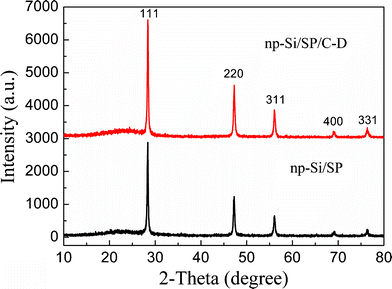 | ||
| Fig. 1 The XRD patterns of the np-Si/SP and np-Si/SP/C-D composites. | ||
The morphology of the as-prepared np-Si/SP is demonstrated by SEM and TEM in Fig. 2. Irregular pores and compact Si particles coexist in as-prepared silicon powders. The pores arise from LiCl completely removed from the composite. It is further determined by Brunauer–Emmett–Teller (BET) measurement that specific surface area of the np-Si/SP is 73.9 m2 g−1 (Fig. 3a). Furthermore, the main pore distribution in np-Si/SP lies in 20–50 nm with a cumulative pore volume of 0.596 cm3 g−1, as determined by BJH pore diameter distribution in Fig. 3b. These nanopores may effectively accommodate the volume changes of silicon.10 As shown in Fig. 4a, the particle size of the np-Si/SP/C-D nanoparticles is ranged from 100–200 nm. In contrast, the nano-Si/SP/C-D particles with large primary particle size are severely aggregated (Fig. 4d). After carbon coating via the CVD method, the nanoporous structures are maintained (Fig. 4b), and the core/shell structure with a uniform and partially graphitic carbon shell of ca. 6 nm is observable (Fig. 4c). The lattice fringes with the interplanar spacing of 3.1 Å correspond to Si (111) plane. By contrast, the obtained carbon layer on surface of the np-Si/SP/C-S is amorphous and nonuniform (Fig. 4e). Raman spectrum analyses were employed to confirm degree of carbonization in the np-Si/SP/C-D and np-Si/SP/C-S composite (Fig. 4f). The characteristic peaks at about 1330 cm−1 and 1582 cm−1 are in good agreement with the typical Raman mode of the D-band, and G-band of carbon, respectively. The integrated intensity ratio ID/IG is indicative of the degree of carbonization and a smaller ratio is associated with higher electronic conductivity.30,31 The values for the np-Si/SP/C-D and np-Si/SP/C-S are 0.75 and 1.18, respectively, indicating relatively higher electronic conductivity for np-Si/SP/C-D. According to four-point probe measurements, the practical electronic conductivity of the np-Si/SP/C-D composite material (ca. 0.19 S cm−1) is hundreds of times higher than that of the np-Si/SP/C-S (ca. 1.22 × 10⁻⁴ S cm−1).
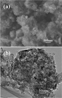 | ||
| Fig. 2 (a) A SEM image of np-Si/SP and (b) a TEM image of np-Si/SP. | ||
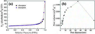 | ||
| Fig. 3 (a) N2 adsorption/desorption isotherm of the np-Si/SP and (b) the pore-size distribution plot calculated by the BJH formula in the desorption branch isotherm of the np-Si/SP. | ||
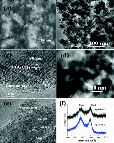 | ||
| Fig. 4 (a) SEM image of the np-Si/SP/C-D composite, (b, c) TEM images of the np-Si/SP/C-D composite, (d) TEM image of the nano-Si/SP/C-D composite, (e) TEM image of the np-Si/SP/C-S composite, and (f) Raman spectrum of the np-Si/SP/C-D composite and the np-Si/SP/C-S composite. | ||
Fig. 5 illustrates the discharge/charge curves of the np-Si/SP and np-Si/SP/C-D composites at a current density of 100 mA g−1. The initial discharge and charge capacity of np-Si/SP electrode are 2748.1, 1927.6 mAh g−1, with an initial coulombic efficiency of 70.1%. During cycling, the capacity drops quickly and voltage polarization is still serious. To enhance the silicon surface electric conductivity and stabilize the whole structure, carbon was employed to modify the np-Si/SP. As shown in Fig. 5b, the first discharge and charge capacity of the np-Si/SP/C-D electrode reach 2134.8 mAh g−1 and 1413.2 mAh g−1, corresponding to its Coulombic efficiency of 66.2%. Carbon coating makes the Coulombic efficiency slightly lower. One reason is that this carbon has a very low Coulombic efficiency for the initial Li intercalation and de-intercalation.10 The reversible capacity of the np-Si/SP/C-D electrode rises with progressive cycle in the initial cycles and then becomes stable. It means that the active material is not completely utilized at the beginning and lithium diffusion and electrochemical kinetics reach an optimal state after several cycles. Additionally, the first discharge curve displays a short step at about 0.75 V and a long flat plateau below 0.1 V, which is consistent with cyclic voltammograms (CVs) of the np-Si/SP/C-D electrode, as exhibited in Fig. 6. The CVs of the np-Si/SP/C-D composite electrode was measured at the scan rate of 0.1 mV s−1. The initial potential of the electrode is about 2.88 V vs. Li/Li+ in the open-circuit state. In the first cathodic scan, the peak at 0.75 V is attributed to the formation of a SEI film, which disappears from the subsequent cycles. The peak at 0.01 V features the Li-insertion process of crystalline Si to form an amorphous LixSi phase. One additional cathodic peak at 0.15 V appears from the second cycle. In the anodic scan, the two peaks at 0.3 V and 0.5 V are observed in the first cycle and become more distinct in the following cycles. These two peaks correspond to de-lithiation of silicon. The peaks and shape of the CV curve are consistent with the results previously reported in the literature for the Si anode.32
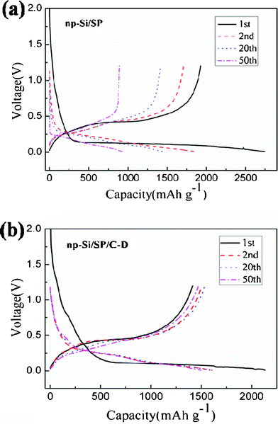 | ||
| Fig. 5 Galvanostatic charge–discharge profiles of the np-Si/SP and np-Si/SP/C-D composite at the 1st, 2nd, 20th and 50th cycle. | ||
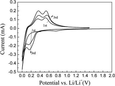 | ||
| Fig. 6 Cyclic voltammograms of the np-Si/SP/C-D composite electrode measured in the voltage region of 0–1.5 V with a scan rate of 0.1 mV s−1 . | ||
To further demonstrate that nanopores and uniform carbon layer are crucial for improving cycling performance of the composite, different carbon coating routes and different Si materials are applied and electrochemical behaviors of the resulting samples are compared and discussed. Fig. 7a compares the cycle capacity and stability for the np-Si/SP, np-Si/SP/C-S and np-Si/SP/C-D composite at a current density of 100 mA g−1. The np-Si/SP electrode presents the highest initial capacity of 1927.6 mAh g−1, but the capacity drops after several cycles and its capacity retention after the 50th cycle is only 52.4% versus the 2nd cycle. In contrast, the np-Si/SP/C-D exhibits an excellent cycling stability with 91.1% capacity retention at the 100th cycle under the same conditions. The remarkable improvement may be due to the fact that the uniform thin carbon layer improves the electronic conductivity and structure stability of the np-Si/SP. For control comparison, the carbon from PVC pyrolysis was also employed on the np-Si/SP and the electrochemical cycling behavior is shown in Fig. 7a. Although silicon source and the carbon content are the same, the initial capacity of the np-Si/SP/C-S composite is only 959.3 mAh g−1, and the capacity fades quickly. Its capacity retention after the 40th cycle is only 73.9% against the 2nd cycle. The great difference is the carbon layer structure. The np-Si/SP/C-D has a uniform thin carbon layer, but the np-Si/SP/C-S presents quite an uneven carbon distribution on the surface. The TEM image of the np-Si/SP/C-D composite shows that silicon particles are well encapsulated in carbon matrix, leading to the stable composite integration and good electronic conductivity. In addition, the carbon on the np-Si/SP/C-D is partially graphitic, which possesses higher conductivity, comparing to the amphous carbon on the np-Si/SP/C-S. It can be concluded that a suitable carbon coating is necessary for increasing the capacity and maintaining the cycling stability.
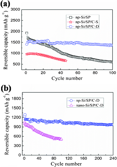 | ||
| Fig. 7 (a) Cycling performance of the np-Si/SP, np-Si/SP/C-D composite and np-Si/SP/C-S composite electrodes at a current density of 100 mA g−1, (b) Cycling performance of the np-Si/SP/C-D and nano-Si/SP/C-D electrodes at a current density of 300 mA g−1. | ||
Fig. 7b illustrates cycling performance of the np-Si/SP/C-D composite, no-porous nano-Si/SP/C-D composite in the voltage range of 0.01–1.2 V (vs. Li+/Li) at a current density of 300 mA g−1. The np-Si/SP/C-D electrode delivers a reversible capacity 1240.8 mAh g−1 in initial cycle and after 200 cycles the reversible capacity is still 982 mAh g−1 with excellent capacity retention of 86% versus the 3rd cycle. However, despite the same carbon type and content, the nano-Si/SP/C-D shows fast capacity decline. The reversible capacity at the initial and 100th is 1052.5 and 508.5 mAh g−1, respectively, with a retention of 50.7% against the second cycle. The different cycling performances of the nano-Si/SP/C-D and np-Si/SP/C-D may be consequences of their structural differences. It is believed that the rich nanopores of the np-Si/SP can endure and buffer the severe volume change of silicon upon lithium insertion and extraction and improve mechanical integrity of the composite. By contrast, the nano-Si/SP/C-D particles are easily aggregated to form compact secondary particles, which is demonstrated by TEM result (Fig. 4d).
Moreover, the np-Si/SP/C-D electrode also shows acceptable rate capacity and high reversibility for lithium storage. As shown in Fig. 8, a reversible capacity near 1480 mAh g−1 is obtained at a current rate of 0.1 A g−1 during the first 5 cycles. Even increasing current density to 8 A g−1(i.e. using 3 min for a complete charge or discharge process), the reversible capacity is still 502.5 mAh g−1. In contrast, the capacity of nano-Si/SP/C-D composite drastically declines from 1248 to 77 mAh g−1, when the current rate is increased in stages from 0.1 to 8 A g−1.
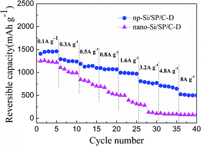 | ||
| Fig. 8 The reversible capacities of the np-Si/SP/C-D and nano-Si/SP/C-D composite cycled at different current rates from 0.1 to 8 A g−1. | ||
Conlusions
A new kind of nanoporous silicon/carbon was successfully prepared via a mechanochemical reaction between SiCl4 and Li13Si4 under ball milling. The whole process of preparing such np-Si/SP is mild and simple, using no corrosive acid. Importantly, this method is suitable for large-scale synthesis of nanoporous silicon based composite for a potential anode material of lithium ion batteries. After surface carbon coating by a CVD method, the np-Si/SP/C-D exhibited a stable reversible capacity of ca.1400 mAh g−1 for 100 cycles and good cycling reversibility, even at high current rate of 8 A g−1. The superior electrochemical performance results from the open nanoporous structure, which can accommodate the volume expansion, and excellent electronic and ionic conductivity of thin carbon layer.References
- F.-F. Cao, Y.-G. Guo and L.-J. Wan, Energy Environ. Sci., 2011, 4, 1634 CAS.
- J. B. Goodenough and Y. Kim, Chem. Mater., 2010, 22, 587 CrossRef CAS.
- J. Li, C. Daniel and D. Wood, J. Power Sources, 2011, 196, 2452 CrossRef CAS.
- J. R. Szczech and S. Jin, Energy Environ. Sci., 2011, 4, 56 CAS.
- H. Kim, M. Seo, M.-H. Park and J. Cho, Angew. Chem., Int. Ed., 2010, 49, 2146 CrossRef CAS.
- I. Kovalenko, B. Zdyrko, A. Magasinski, B. Hertzberg, Z. Milicev, R. Burtovyy, I. Luzinov and G. Yushin1, Science, 2011, 334, 75 CrossRef CAS.
- J. Yang, B. F. Wang, K. Wang, Y. Liu, J. Y. Xie and Z. S. Wen, Electrochem. Solid-State Lett., 2003, 6, A154 CrossRef CAS.
- J. Xiao, W. Xu, D. Wang, D. Choi, W. Wang, X. Li, G. L. Graff, J. Liu and J.-G. Zhang, J. Electrochem. Soc., 2010, 157, A1047 CrossRef CAS.
- T. Song, J. Xia, J.-H. Lee, D. H. Lee, M.-S. Kwon, J.-M. Choi, J. Wu, S. K. Doo, H. Chang, W. I. Park, D. S. Zang, H. Kim, Y. Huang, K.-C. Hwang, J. A. Rogers and U. Paik, Nano Lett., 2010, 10, 1710 CrossRef CAS.
- H. Jia, P. Gao, J. Yang, J. Wang, Y. Nuli and Z. Yang, Adv. Energy Mater., 2011, 1, 1036 CrossRef CAS.
- H. K. Liu, Z. P. Guo, J. Z. Wang and K. Konstantinov, J. Mater. Chem., 2010, 20, 10055 RSC.
- S. H. Ng, J. Wang, D. Wexler, S. Y. Chew and H. K. Liu, J. Phys. Chem. C, 2007, 111, 11131 CAS.
- Y. X. Yin, S. Xin, L. J. Wan, C. J. Li and Y. G. Guo, J. Phys. Chem. C, 2011, 115, 14148 CAS.
- D. Ahn and R. Raj, J. Power Sources, 2011, 196, 2179 CrossRef CAS.
- M. Holzapfel, H. Buqa, W. Scheifele, P. Novák and F.-M. Petrat, Chem. Commun., 2005, 1566 RSC.
- T. Zhang, J. Gao, L. J. Fu, L. C. Yang, Y. P. Wu and H. Q. Wu, J. Mater. Chem., 2007, 17, 1321 RSC.
- L. J. Fu, H. Liu, H. P. Zhang, C. Li, T. Zhang, Y. P. Wu, R. Holze and H. Q. Wu, Electrochem. Commun., 2006, 8, 1 CrossRef CAS.
- P. Gao, Y. Nuli, Y.-S. He, J. Wang, A. I. Minett, J. Yang and J. Chen, Chem. Commun., 2010, 46, 9149 RSC.
- S. Yang, G. Li, Q. Zhu and Q. Pan, J. Mater. Chem., 2012, 22, 3420 RSC.
- Y. Liu, Z. Y. Wen, X. Y. Wang, A. Hirano, N. Imanishi and Y. Takeda, J. Power Sources, 2009, 189, 733 CrossRef CAS.
- G. X. Wang, J. Yao and H. K. Liu, Electrochem. Solid-State Lett., 2004, 7, A250 CrossRef CAS.
- A. Magasinski, P. Dixon, B. Hertzberg, A. Kvit, J. Ayala and G. Yushin, Nat. Mater., 2010, 9, 353 CrossRef CAS.
- S. Guo and S. Dong, Chem. Soc. Rev., 2011, 40, 2644 RSC.
- Y. Yao, M. T. McDowell, I. Ryu, H. Wu, N. Liu, L. Hu, W. D. Nix and Y. Cui, Nano Lett., 2011, 11, 2949 CrossRef CAS.
- J. Cho, J. Mater. Chem., 2010, 20, 4009 RSC.
- C. Du, C. Gao, G. Yin, M. Chen and L. Wang, Energy Environ. Sci., 2011, 4, 1037 CAS.
- H. Kim, B. Han, J. Choo and J. Cho, Angew. Chem., Int. Ed., 2008, 47, 10151 CrossRef CAS.
- J. P. Rong, C. Masarapu, J. Ni, Z. J. Zhang and B. Q. Wei, ACS Nano, 2010, 4, 4683 CrossRef CAS.
- J. R. Szczech and S. Jin, Energy Environ. Sci., 2011, 4, 56 CAS.
- F. Tuinstra, J. Chem. Phys., 1970, 53, 1126 CrossRef CAS.
- Y.-D. Cho, G. T.-K. Fey and H.-M. Kao, J. Power Sources, 2009, 189, 256 CrossRef CAS.
- A. Esmanski and G. A. Ozin, Adv. Funct. Mater., 2009, 19, 1999 CrossRef CAS.
| This journal is © The Royal Society of Chemistry 2012 |
