Solvothermal synthesis and luminescence properties of BaCeF5, and BaCeF5:Tb3+ nanocrystals
Tianqi
Sheng
ab,
Zuoling
Fu
*ab,
Jing
Wang
ab,
Xihong
Fu
d,
Yingning
Yu
c,
Shihong
Zhou
c,
Siyuan
Zhang
c and
Zhenwen
Dai
*ab
aState Key Laboratory of Superhard Materials, College of Physics, Jilin University, Changchun, 130012, China. E-mail: zlfu@jlu.edu.cn (Z. Fu); dai@jlu.edu.cn (Z. Dai); Fax: 86-431-85167966; Tel: 86-431-85167966
bKey Lab of Coherent Light, Atomic and Molecular Spectroscopy, Ministry of Education, Changchun, 130012, China
cState Key Laboratory of Rare Earth Resources Utilization, Changchun Institute of Applied Chemistry, Chinese Academy of Sciences, Changchun, 130022, China
dChangchun Institute of Optics, Fine Mechanics and Physics, Chinese Academy of Sciences, Changchun, 130033, China
First published on 7th March 2012
Abstract
Cubic monodisperse BaCeF5 and BaCeF5:Tb3+ nanocrystals have been successfully synthesized by a citric acid assisted solvothermal method. The crystalline phase, size, morphology, and luminescence properties were characterized using powder X-ray diffraction (XRD), field emission-scanning electron microscopy (FE-SEM), transmission electron microscopy (TEM), photoluminescence (PL), photoluminescent excitation spectra (PLE) as well as dynamics decay. The results reveal that the Tb3+-doped BaCeF5 sample shows a strong green emission centered at 546 nm, corresponding to the 5D4→7F5 transition of Tb3+ due to an efficient energy transfer from Ce3+ to Tb3+. The decay lifetime of Ce3+ monotonically increases with increase of Tb3+ concentration. The critical energy transfer distance between Ce3+ and Tb3+ was also calculated by methods of concentration quenching and spectral overlapping. Experimental analysis and theoretical calculations reveal that the dipole–dipole interaction should be the dominant mechanism for the Ce3+–Tb3+ energy transfer.
1. Introduction
Over the past few decades, the study of nanometric luminescent materials, especially lanthanide ion-doped luminescent nanomaterials, has become one of the hottest topics in nanoscience because of their potential applications in high performance magnets, luminescent devices, catalysts, and other functional materials arising from 4f electrons.1–5 As an important group of inorganic materials with unique optical and electronic properties, nano and submicroscale fluoride materials have drawn increasing attention. For example, the syntheses of metal fluoride nanomaterials, such as CaF2 nanocubes,6,7 SrF2 nanospheres,8 and BaF2 nanocubes9 and nanorods10 have been reported for their application in UV lithography, UV-transparent optical lenses, and surface conditioning of glass. Besides, binary lanthanide fluorides (LnF3, Ln = lanthanide elements)11–14 and ternary ALnF4 (A = alkali metals, Ln = lanthanide elements)15–22 fluorides were intensively researched with potential applications in display, laser, and biological labels in recent years. Compared with the fluorides mentioned above, alkaline-earth lanthanide ternary fluorides have obtained relatively little attention. Barium yttrium fluoride crystals such as BaY2F8 and BaYF5 are prepared19 as excellent host matrixes that can be doped with divalent and trivalent lanthanide ions, exhibiting the strong broadband emission in the near UV spectra region (360–440 nm)23 and highly efficient infrared-to-visible up-conversion light.24 However, the lanthanide ions doped BaCeF5 system has never reported up to now.In general, alkaline-earth lanthanide ternary fluorides, for examples, bulk BaLn2F8/BaYF5 crystals25,26 and nonstoichiometric single crystals R1−yMyF3−y (R = La–Er; M = Ca, Sr, Ba, Cd)27 were prepared by traditional solid-state reaction method. Due to insufficient mixing and low reactivity of raw materials, several impurity phases easily co-exist in the product. Therefore, in recent years, several wet chemical techniques such as co-precipitation method,28 hydrothermal method,29–31 liquid-solid-solution procedure32,33 and solvothermal method34 were used to prepare the fluorides phosphor. Phosphor materials synthesized by these wet chemical methods have many advantages, i.e., high purity, homogenous composition and fine grains in the nanometer range. To the best of our knowledge, there has been no literature available on the wet chemical synthesis of cubic-phase BaCeF5, so we have undertaken this work. In this paper, we realize the solvothermal synthesis of BaCeF5, and BaCeF5:Tb3+ nanocrystals and research the luminescence properties of Ce3+ and Tb3+ in cubic BaCeF5. Moreover, the energy transfer efficiency from Ce3+ to Tb3+, the energy transfer critical distance (Rc) between Ce3+ and Tb3+, and the energy transfer mechanism of Ce3+–Tb3+ in BaCe1−xTbxF5 nanocrystals have been discussed in detail.
2. Experimental
2.1. Synthesis of the samples
2.2. Characterization
The structural characteristics of the final products were examined by the powder X-ray diffraction (XRD) pattern using Cu-Kα (λ = 0.15405 nm) radiation on a Rigaku-Dmax 2500 diffractometer. The morphology and the size of the obtained samples were observed with field emission-scanning electron microscopy (FE-SEM, JSM-6700F, JEOL) and transmission electron microscopy (TEM, JEM-2010 JEOL). The ultraviolet-visible photoluminescence excitation and emission spectra were recorded with a Hitachi F-7000 spectrophotometer equipped with Xe-lamp as an excitation source. All the measurements were performed at room temperature.3. Results and discussion
3.1. Crystal structure and morphologies
Fig. 1 presents representative XRD patterns of BaCe1−xTbxF5 samples with different concentrations. The powder XRD data of the as-synthesized product shows nine characteristic diffraction peaks (25.61°, 29.67°, 42.50°, 50.28°, 52.69°, 61.61°, 67.81°, 69.81°, 77.62°) in 2θ range of 10° to 80°. Compared with the cubic structure BaCeF5 (JCPDS # 43-0394, space group Fm-3m[225], cell parameters a = b = c = 6.018 Å), the absence of some diffraction peaks implies that the crystal structure of the as-synthesized product may have a higher symmetry in the space group. No impurity lines are observed in the patterns of the Tb3+ doped nanocrystals shown in Fig. 1(b)–(h), meaning that the RE3+ doping does not cause any significant changes in the crystal phases. In addition, it is worth noting that the diffraction peaks are widened as a result of the small-size effect of the nanocrystals. The mean crystallite size of the product was estimated from the XRD pattern according to the Scherrer formula D = Kλ/βcosθ, where λ is the X-ray wavelength (0.15406 nm), β is the full-width at half-maximum, θ is the diffraction angle, and K is a constant (0.89). The estimated mean crystallite size is 38.05 nm. | ||
| Fig. 1 XRD patterns of samples BaCe1−xTbxF5 and reference date JCPDS#43-0394. | ||
A representative panoramic FE-SEM image shown in Fig. 2(a) demonstrates that the product is composed of well dispersed particles with small sizes. The high-magnified TEM image (Fig. 2(b)) further shows the nanocrystals more distinctly. Most of the nanocrystals are pseudospherical particles with a mean size of about 40 nm, which is in consistent with the size estimated by Scherrer formula from the XRD pattern. The selected-area electron diffraction (SAED) in Fig. 2(c) exhibits dots, which are due to the diffraction of ensemble nanocrystals, indicating that the as-obtained nanocrystals are essentially single crystalline in nature. The interplanar distance obtained from the dot is 0.3475 nm, which can be assigned to (111) lattice planes of cubic structure BaCeF5, respectively. In Fig. 2(d) the interplanar distance is 0.3475 nm, which is also matched with the (111) plane.
 | ||
| Fig. 2 (a) FE-SEM image of BaCe0.90Tb0.10F5 sample. (b) TEM image of the sample. (c) SAED pattern of the particle. (d) HRTEM image of the sample. | ||
3.2. Luminescence properties
Fig. 3(a) shows the photoluminescence excitation (λem = 344 nm) and photoluminescence emission (λex = 292 nm) spectra of the BaCeF5 nanocrystals. The excitation spectrum of the BaCeF5 nanocrystals gives a broadband centered at 292 nm with a shoulder centered at 270 nm, which were attributed to the electric dipole-allowed transitions of the Ce3+ ions from the 4f shell to the 5d orbital. Owing to the influences of crystal field splitting and spin–orbit coupling, the 4f→5d transition of the Ce3+ ions will exhibit a subtle structure.35 Under excitation at 292 nm, the emission spectrum of BaCeF5 nanocrystals exhibits an intense ultraviolet emission band centered at 344 nm, which is assigned to the 5d–4f electronic transition of the Ce3+ ions. Fig. 3(b) shows the photoluminescence excitation (λem = 546 nm) spectrum of the BaCe0.98Tb0.02F5 nanocrystals and photoluminescence emission (λex = 292 nm) spectrum of the BaCeF5 nanocrystals. The photoluminescence excitation (λem = 546 nm) spectrum of BaCe0.98Tb0.02F5 nanocrystals in the Fig. 3(b) are similar with the photoluminescence excitation (λem = 344 nm) spectrum of the BaCeF5 nanocrystals in the Fig. 3(a). On the basis of the above photoluminescence excitation spectrum of the Tb3+ doped samples and photoluminescence spectrum of no Tb3+ doped samples, we can find that the emission band of Ce3+ overlaps well with the excitation band of Tb3+. Therefore, it is expected that a resonance-type energy transfer from Ce3+ to Tb3+ in the Tb3+ doped BaCeF5 nanocrystals may occur. | ||
| Fig. 3 (a) Excitation spectrum (λem = 344 nm) and emission spectrum (λex = 292 nm) of BaCeF5. (b) Excitation spectrum (λem = 546 nm) of BaCe0.98Tb0.02F5 and emission spectrum (λex = 292 nm) of BaCeF5. | ||
Fig. 4 gives the photoluminescence excitation (λem = 546 nm) and photoluminescence emission (λex = 292 nm) spectra of the BaCe0.86Tb0.14F5 nanocrystals. By monitoring the 546 nm emission of Tb3+, the BaCe0.86Tb0.14F5 nanocrystal shows a broad excitation band peaking at 292 nm. With 292 nm excitation, the photoluminescence emission spectrum of BaCe0.86Tb0.14F5 has characteristic transitions of forbidden 4f–4f transitions within the Tb3+ configuration in the wavelength range of 490–640 nm. The characteristic emissions of Tb3+ at 495, 546, 585, and 625 nm can be attributed to the transitions 5D4→7F6, 5D4→7F5, 5D4→7F4, and 5D4→7F3, respectively. The green emission (5D4→7F5) at 546 nm,36 which is a magnetic dipole transition with ΔJ = 1, is more intense than the other transitions.37
 | ||
| Fig. 4 Excitation (λem = 546 nm) and emission (λex = 292 nm) spectra of BaCe0.86Tb0.14F5 . | ||
To explore the possibility of the energy transfer from the Ce3+ to Tb3+ ions, Tb3+ ions with different concentrations were doped into the BaCeF5 nanocrystals. Fig. 5 displays the emission spectra of the BaCe1−xTbxF5 nanocrystals with different Tb3+ concentrations, it contains both the weak emission of the Ce3+ ions and the strong green emission of the Tb3+ ions. The emission intensity of the Tb3+ ions gradually increases at the expense of that of the Ce3+ ions with the increase of Tb3+ doping concentration, indicating that the energy transfer from the Ce3+ to Tb3+ ions is highly efficient since the emission band of the Ce3+ ions matches well with the f–f absorptions of the Tb3+ ions. Until BaCe0.90Tb0.10F5, the emission intensity of Tb3+ ions reaches the strongest and then the emission intensity of Tb3+ ions gradually decreases with the increase of Tb3+ doping concentration.
 | ||
| Fig. 5 Emission spectra of BaCe1−xTbxF5 (λex = 292 nm). | ||
In order to investigate the luminescence dynamics of the samples, we measured the photoluminescence decay curves and then calculated the lifetime as well as energy transfer efficiencies. All the decay curves can be well fitted by a single exponential function as I(t) = I0exp(−t/τ), where I0 is the initial emission intensity at t = 0, τ is the 1/e lifetime of Tb3+. The lifetimes of Tb3+ in BaCe1−xTbxF5 samples are 2.80 ± 0.03, 2.36 ± 0.02, 2.14 ± 0.02, 1.70 ± 0.02, 1.66 ± 0.03, 1.44 ± 0.01, 1.36 ± 0.01, 1.19 ± 0.03, 1.16 ± 0.02, and 1.15 ± 0.01 ms for x = 0.02, 0.04, 0.06, 0.08, 0.10, 0.12, 0.14, 0.16, 0.18 and 0.20, respectively.
On the basis of the above results, Ce3+ acts as a sensitizer to yield sensitized luminescence from Tb3+ in BaCeF5. A simple operational definition of energy transfer efficiency ηT in terms of lifetimes is given by:
 | (1) |
 | (2) |
 | ||
| Fig. 6 Energy transfer efficiency ηT in BaCe1-xTbxF5. | ||
According to the energy transfer theories of Dexter and Schulman, concentration quenching is due to the energy transfer from one activator to another in many cases until an energy sink in the lattice is reached.40 We approximated the unit cell as a sphere. The volume of the sphere can be expressed as follows:  , (where r is the radius of the sphere, N is the number of sites that a lanthanide ion can occupy per unit cell, V is the volume of the unit cell). According to the above experimental results and the crystal structure of the BaCeF5 nanocrystal, we use V = 219.2 Å3, N = 2, and estimate the average separation RCe–Ce = 2r = 5.94 Å. In Fig. 5, it has been shown that the critical concentration of CTb is 0.10. As suggested by Verstegen et al.,41 the critical distance of the Ce3+–Ce3+ is the critical distance of Ce3+–Tb3+, because the Tb3+ ions replace the position of the Ce3+ ions in the each unit cell. So in the host of BaCeF5 nanocrystals, the critical concentration of CTb is 0.10 and the corresponding critical distance Rc for the Ce3+–Tb3+ energy transfer is about 5.94 Å.
The energy transfer from a sensitizer to an activator can take place via radiative energy transfer, exchange interaction, and multipole-multipole interaction.42 In general, the existence of radiative energy transfer from a sensitizer to an activator can be confirmed by the spectral dips in the emission spectrum of the sensitizer. The absence of the dips in the emission band of the Ce3+ ions corresponding to the f–f absorption lines of the Tb3+ ions means that the radiative energy transfer between the Ce3+ ions and the Tb3+ ions can be neglected. Moreover, the radiative energy transfer does not change the decay time of the sensitizer. The decrease of the decay time of the Ce3+ ions also does not support a radiative energy transfer process. Exchange interaction is strongly influenced by the distance between the sensitizer and activator and needs a large overlapping between sensitizer and activator orbitals. While both the Ce3+ and Tb3+ ions are reducing ions, such an exchange would require very high energy. Generally, the value of the critical distance is about 3–4 Å if the exchange is dominated.43 In our case, the critical distance of Ce3+ and Tb3+ is estimated to be 5.94 Å, suggesting that energy transfer via exchange interaction can be excluded either. Thus we suspected that the energy transfer in BaCe1−xTbxF5 nanocrystals takes place via electric multipole–multipole interaction. On the basis of Dexter's energy transfer formula of multi-polar interaction and Reisfeld's approximation,41,44,45 the following relation can be given as:
 | (3) |
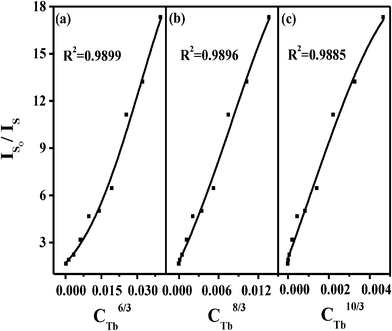 | ||
| Fig. 7 Dependence of IS0/IS of Ce3+ on (a)CTb6/3, (b)CTb8/3, and (c)CTb10/3. | ||
According to Dexter's energy transfer theory,45 the energy transfer process through multipolar interaction depends on the extent of overlap of the emission spectrum of the sensitizer with the absorption spectrum of the activator, the relative orientation of interacting dipoles and the distance between the sensitizer and the activator. For a dipole–dipole interaction, the energy transfer probability (PSA) from a sensitizer to an activator is given by the following formula:
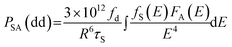 | (4) |
The critical distance (Rc) of the energy transfer from the sensitizer to activator is defined as the distance for which the probability of transfer equals the probability of radiative emission of the sensitizer, i.e., the distance for which PSA ×τs = 1. Therefore, Rc can be obtained from eqn (5):
 | (5) |
The fd of the Tb3+ transition is 0.3 × 10−6.41 Using this value and the calculated spectral overlap, the critical distance for a dipole–dipole interaction mechanism is estimated to be 5.89 Å, which little deviates from the value estimated from the critical concentration (5.94 Å), indicating that the electric dipole–dipole interaction as the main energy transfer mechanism. In addition, the dipole–dipole interaction can generally be expected to dominate in the energy transfer when both the sensitizer and the activator ions are characterized by electric dipole-allowed transitions, while the f–f transitions of Tb3+ are allowed by the selection rules of electric dipole transitions. Further, the dipole–dipole interaction mechanism in the energy transfer can be determined, too. According to the above results, we believe that the energy transfer mechanism from Ce3+ to Tb3+ in the BaCeF5 host should be predominated by dipole–dipole interactions.46
4. Conclusion
In summary, a simple solvothermal method has been used to prepare BaCeF5 and BaCeF5:Tb3+ nanocrystals. The XRD, FE-SEM and TEM analysis indicated that the samples crystallizes in a cubic structure with spherical morphology and an average diameter of 40 nm. The photoluminescence spectra of BaCe1−xTbxF5 nanocrystals demonstrate that the energy transfer from Ce3+ to Tb3+ is highly efficient. The photoluminescence spectra of the BaCe1−xTbxF5 nanocrystals show this result, as the concentration quenching phenomenon occurs when the x = 0.10. The average separation between Ce3+ and Tb3+ is calculated and the critical distance Rc is 5.94 Å determined by the method of concentration quenching. The Rc calculated by spectral overlapping method proves this. By comparison of theoretical calculation results to those of experiments, we can infer that the energy transfer from Ce3+ to Tb3+ in the nanocrystals occurs predominantly via the dipole–dipole interaction.Acknowledgements
This work was supported by the National Science Foundation of China (no. 11004081), partially supported by the Science and Technology Innovation Projects of Jilin Province for overseas students and by the Open Project of State Key Laboratory of Rare Earth Resources Utilization, Changchun Institute of Applied Chemistry, Chinese Academy of Sciences (RERU2011005).References
- W. Xu, Y. Wang, X. Bai, B. Dong, Q. Liu, J. S. Chen and H. W. Song, J. Phys. Chem. C, 2010, 114, 14018–14024 CAS.
- C. X. Li and J. Lin, J. Mater. Chem., 2010, 20, 6831–6847 RSC.
- T. Yu, J. Joo, Y. I. Park and T. Hyeon, Angew. Chem., Int. Ed., 2005, 44, 7411–7414 CrossRef CAS.
- H. X. Mai, Y. W. Zhang, R. Si, Z. G. Yan, L. D. Sun, L. P. You and C. H. Yan, J. Am. Chem. Soc., 2006, 128, 6426–6436 CrossRef CAS.
- M. Yu, H. Wang, C. K. Lin, G. Z. Li and J. Lin, Nanotechnology, 2006, 17, 3245–3252 CrossRef CAS.
- X. M. Sun and Y. D. Li, Chem. Commun., 2003, 1768–1769 RSC.
- C. M. Zhang, C. X. Li, C. Peng, R. Chai, S. S. Huang, D. M. Yang, Z. Y. Cheng and J. Lin, Chem.–Eur. J., 2010, 16, 5672–5680 CAS.
- Y. Jin, W. P. Qin and J. S. Zhang, J. Fluorine Chem., 2008, 129, 515–518 CrossRef CAS.
- P. Gao, Y. Xie and Z. Li, Eur. J. Inorg. Chem., 2006, 3261–3265 CrossRef CAS.
- G. H. De, W. P. Qin, J. S. Zhang, J. S. Zhang, Y. Wang, C. Y. Cao and Y. Cui, J. Solid State Chem., 2006, 179, 955–958 CrossRef CAS.
- H. Hu, Z. G. Chen, T. Y. Cao, Q. Zhang, M. X. Yu, F. Y. Li, T. Yi and C. H. Huang, Nanotechnology, 2008, 19, 375702–375712 CrossRef.
- C. X. Li, J. Yang, P. P. Yang, H. Z. Lian and J. Lin, Chem. Mater., 2008, 20, 4317–4326 CrossRef CAS.
- X. L. Yang, S. G. Xiao, J. W. Ding and X. H. Yan, J. Appl. Phys., 2008, 103, 093101 CrossRef.
- Z. L. Wang, Z. W. Quan, P. Y. Jia, C. K. Lin, Y. Lou, Y. Chen, J. Fang, W. Zhou, C. J. O'Connor and J. Lin, Chem. Mater., 2006, 18, 2030–2037 CrossRef CAS.
- J. L. Zhuang, J. Wang, X. F. Yang, I. D. Williams, W. Zhang, Q. Y. Zhang, Z. M. Feng, Z. M. Yang, C. L. Liang, M. M. Wu and Q. Su, Chem. Mater., 2009, 21, 160–168 CrossRef CAS.
- P. Ptacek, H. Schäfer, K. Kömpe and M. Haase, Adv. Funct. Mater., 2007, 17, 3843–3848 CrossRef CAS.
- X. Liang, X. Wang, J. Zhuang, Q. Peng and Y. D. Li, Adv. Funct. Mater., 2007, 17, 2757–2765 CrossRef CAS.
- Z. J. Wang, F. Tao, W. L. Cai, L. Z. Yao and X. G. Li, Solid State Commun., 2007, 144, 255–258 CrossRef CAS.
- Y. J. Huang, H. P. You, G. Jia, Y. H. Song, Y.H. Zheng, M. Yang, K. Liu and N. Guo, J. Phys. Chem. C, 2010, 114, 18051–18058 CAS.
- C. C. Cao, H. K. Yang, J. W. Chung, B. K. Moon, B. C. Choi, J. H. Jeong and K. H. Kim, J. Mater. Chem., 2011, 21, 10342–10347 RSC.
- D. M. Yang, C. X. Li, G. G. Li, M. M. Shang, X. J. Kang and J. Lin, J. Mater. Chem., 2011, 21, 5923–5927 RSC.
- D. G. Yang, X. J. Kang, M. M. Shang, G. G. Li, C. Peng, C. X. Li and J. Lin, Nanoscale, 2011, 3, 2589–2595 RSC.
- X. R. Liu, G. Xu and C. P. Richard, J. Solid State Chem., 1986, 62, 83–91 CrossRef CAS.
- L. F. Johnson, H. J. Guggenheim, T. C. Rich and F. W. Ostermayer, J. Appl. Phys., 1972, 43, 1125–1137 CrossRef CAS.
- S. Bigotta, D. Parisi, L. Bonelli, A. Toncelli and M. Tonelli, J. Appl. Phys., 2006, 100, 013109 CrossRef.
- V. Toccafondo, S. A. Cerqueira and S. Faralli, J. Appl. Phys., 2007, 101, 023104 CrossRef.
- N. I. Sorokin and B. P. Sobolev, Phys. Solid State, 2011, 50, 416–421 CrossRef.
- G. S. Yi, H. C. Lu, S. Y. Zhao, G. Yue, W. J. Yang, D. P. Chen and L. H. Guo, Nano Lett., 2004, 4, 2191–2196 CrossRef CAS.
- J. Zhuang, L. Liang, H. H. Y. Sung, X. Yang, M. Wu, I. D. Williams, S. Feng and Q. Su, Inorg. Chem., 2007, 46, 5404–5410 CrossRef CAS.
- F. Zhang, J. Li, J. Shan, L. Xu and Dm. Zhao, Chem.–Eur. J., 2009, 15, 11010–11019 CrossRef CAS.
- X. Wang and Y. Li, Chem.–Eur. J., 2003, 9, 5627–5635 CrossRef CAS.
- X. Wang, J. Zhuang, Q. Peng and Y. Li, Inorg. Chem., 2006, 45, 6661–6665 CrossRef CAS.
- S. Li, T. Xie, Q. Peng and Y. Li, Chem.–Eur. J., 2009, 15, 2512–2517 CrossRef CAS.
- H. Mai, Y. Zhang, R. Si, Z. Yan, L. Sun, L. You and C. Yan, J. Am. Chem. Soc., 2006, 128, 6426–6436 CrossRef CAS.
- H. Lai, A. Bao, Y. M. Yang, Y. C. Tao, H. Yang, Y. Zhang and L. L. Han, J. Phys. Chem. C, 2008, 112, 282–286 CAS.
- M. Yu, J. Lin, J. Fu, H. J. Zhang and Y. C. Han, J. Mater. Chem., 2003, 13, 1413–1419 RSC.
- S. D. Cheng, C. H. Kam and S. Buddhudu, Mater. Res. Bull., 2001, 36, 1131–1137 CrossRef CAS.
- G. A. Kumar, P. R. Biju, G. Jose and N. V. Unnikrishnan, Mater. Chem. Phys., 1999, 60, 247–255 CrossRef.
- P. I. Paulose, G. Jose, V. Thomas, N. V. Unnikrishnan and M. K. R. Warrier, J. Phys. Chem. Solids, 2003, 64, 841–846 CrossRef CAS.
- D. L. Dexter and J. A. J. Schulman, Chem. Phys., 1954, 22, 1063–1070 CAS.
- J. M. P. J. Verstegen, J. L. Sommerdijk and J. G. Verriet, J. Lumin., 1973, 6, 425–431 CrossRef CAS.
- G. K. Liu and B. Jacquier, Spectroscopic Properties of Rare Earthsin Optical Materials, Springer, Beijing, 2005 Search PubMed.
- B. M. Antipeuko, I. M. Bataev, V. L. Ermolaev, E. I. Lyubimov and T. A. Privalova, Opt. Spectrosc., 1970, 29, 177 Search PubMed.
- U. aldiño. G, J. Phys.: Condens. Matter, 2003, 15, 3821–3830 CrossRef.
- D. L. Dexter, J. Chem. Phys., 1953, 21, 836–850 CrossRef CAS.
- Z. Zhang, J. Wang, M. Zhang, Q. Zhang and Q. Su, Appl. Phys. B: Lasers Opt., 2008, 91, 529–537 CrossRef CAS.
| This journal is © The Royal Society of Chemistry 2012 |