Porous Mn2O3 microsphere as a superior anode material for lithium ion batteries†
Yuanfu
Deng
*ab,
Zhanen
Li
bc,
Zhicong
Shi
*bc,
Hui
Xu
b,
Feng
Peng
a and
Guohua
Chen
*bc
aKey Laboratory fuel cell of Guangdong province, School of Chemistry and Chemical Engineering, South China University of Technology, Guangzhou, 510640, China. E-mail: chyfdeng@scut.edu.cn
bCentre for Green Products and Processing Technologies, Guangzhou HKUST Fok Ying Tung Research Institute, Guangzhou, 511458, China. E-mail: zhicong@ust.hk
cDepartment of Chemical and Biomolecular Engineering, The Hong Kong University of Science and Technology, Hong Kong, China. E-mail: kechengh@ust.hk
First published on 27th March 2012
Abstract
Porous Mn2O3 microspheres have been synthesized by morphology-controlled decomposition of spherical MnCO3 precursors at 600 °C. The porous Mn2O3 microspheres show a good rate capability and a high specific capacity of 796 mA h g−1 after 50 cycles.
Rechargeable lithium ion batteries (LIBs) have become the dominant power source for portable electronic devices in the past two decades.1 They have also been considered to be the major player in powering pure electric or hybrid electric vehicles. Since it is important to have the specific energy density to approach that of gasoline, the ever-growing need for batteries with high energy density along with good safety have been the trend for intensive research of novel electrode materials.2 Nanostructured metal oxides, such as FeOx, Co3O4, NiO, and SnO2, are among the most widely investigated alternative anode materials for LIBs because of their higher specific capacities than graphite.3 Particularly, Fe3O4 represents a significant advance because of its low price and good conductivity.4 Compared with iron, cobalt and Ni-based oxides, manganese-based oxides have lower operating voltages (average discharge and charge voltages of 0.5 and 1.2 V, respectively). In general, anode materials with lower charge (the discharge process of a battery) voltages versus Li/Li+ can deliver a higher energy density.5 Therefore, investigations of Mn-based anodes have received great interest recently.6 Although Mn2O3 has a high specific theoretical capacity (1018 mA h g−1) as an anode material for LIBs, previous reports6c,6d,6j have claimed that the capacity retention of this material is generally very poor, except for the straw-sheaf-shaped Mn2O3.6k It is well known that the sizes and morphologies of the electrode materials have very important effects on the electrochemical performance of the battery.7 Furthermore, micron-sized spherical materials with suitable porous structures can not only increase their energy density, but also improve their rate capabilities.8 Combining porous spherical structures concept and simple synthetic technique, herein, we successfully synthesized porous Mn2O3 microspheres by morphology-controlled decomposition of spherical MnCO3 precursors. The porous Mn2O3 microspheres show good electrochemical performance as anode materials for LIBs, as seen subsequently.
Uniform, micron-sized MnCO3 spheres were first synthesized by using widely available MnCl2·4H2O and urea as raw materials, and ethylene glycol (EG) as the solvent. The reaction temperature was maintained at 200 °C for 24 h. After thermal decomposition of spherical MnCO3 at 600 °C for 2 h in air, porous Mn2O3 microspheres were obtained. Based on the previous result,9 we chose 600 °C as the calcining temperature of the MnCO3 sample to prepare Mn2O3. Fig. 1 shows the XRD patterns of the MnCO3 microspheres and porous Mn2O3 microspheres. Pure rhombohedral MnCO3 (JCPDS Card No. 44-1472) and orthorhombic Mn2O3 (JCPDS Card No. 24-0508) are obtained.
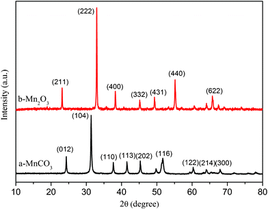 | ||
| Fig. 1 XRD patterns of (a) MnCO3 and (b) Mn2O3 obtained from thermal decomposition of MnCO3 under air atmosphere at 600 °C for 2 h. | ||
Fig. 2a and 2b are typical SEM images of the obtained MnCO3 microspheres. They show a dense spherical morphology with a uniform size distribution ranging from 6 to 8 μm. The rough surface of as-prepared MnCO3 microspheres is composed of tiny grains. After heating under air atmosphere at 600 °C for 2 h, MnCO3 microspheres will be decomposed into porous Mn2O3 microspheres. The particle size is also around 6–8 μm. The features of the porous Mn2O3 microspheres are characterized by nitrogen sorption–desorption. The sample exhibits a type II isotherm with a hysteresis loop, which is characteristic of macroporous materials (Fig. S1†).
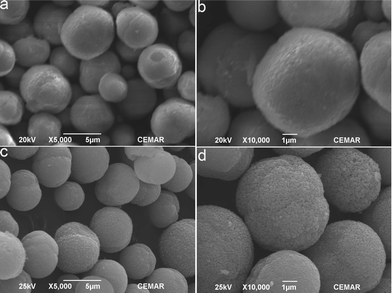 | ||
| Fig. 2 Scanning electron micrographs of MnCO3 (a and b) and Mn2O3 (c and d) obtained by thermal decomposition of MnCO3 under air atmosphere at 600 °C for 2 h. | ||
Fig. 3 shows the cyclic voltammetry (CV) profiles of the porous Mn2O3 microspheres for the first three cycles in the voltage range 0.01–3.0 V versus Li/Li+ at a scan rate of 0.1 mV s−1. The CV curve for the first cycle is substantially different from those of the subsequent ones. The two peaks centred at 1.25 and 0.90 V in the first cathodic process could be associated with the reduction of Mn3+ to Mn2+ and an irreversible reaction related to the lithium ion insertion of the conductive agent AC (AC = acetylene black), respectively.6 Another main peak centred at 0.20 V is attributed to the reduction of MnO to Mn0. In the subsequent cycles, a broad peak at ∼ 1.25 V may be attributed to the incomplete reduction of Mn3+ to Mn2+, and the main cathodic peak shifts to about 0.30 V, which is ascribed to Mn2+ to Mn0. During the anodic process, two peaks are observed at 1.25 V and 2.35 V. These are presumably associated with the oxidation of Mn0 to Mn2+ and Mn2+ to Mn3+, respectively. Compared with the first discharge process, the peak current and the integrated area of this process decrease, indicating capacity loss during the charging process. However, in all of the three charging cycles, the integrated areas remain almost equivalent, indicating good capacity retention after the first discharge process.
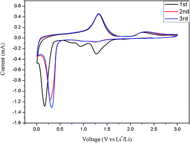 | ||
| Fig. 3 Cyclic voltammetry plots of the Mn2O3 electrode at a scan rate of 0.1 mV s−1 in the voltage range 0.0–3.0 V versus Li+/Li. | ||
Fig. 4a and 4b illustrate the discharge–charge profiles and cycling performance of the porous Mn2O3 microspheres as anode materials for LIBs. The voltage profile of Mn2O3 between 3.00 and 0.01 V in the first discharge can be divided into four distinct voltage regions. The first region starts from the open circuit voltage (∼3.0 V) and shows a continuous decrease in voltage to 1.25 V, resulting in a voltage plateau at 1.25 V and extending to a total of 0.67 moles of Li consumption. This could be associated with the reduction of Mn2O3 to Mn3O4. The voltage then decreases to ∼0.38 V with a new plateau observed. The capacity of 300 mA h g−1 up to the voltage of 0.38 V in this region may be attributed to the reduction of Mn3O4 to MnO and irreversible reactions between Li+ and AC (the discharge–charge curves of AC are shown in Fig. S2†). In the third region, the phase transformation reaction happens with the complete reduction of MnO to Mn and the formation of amorphous Li2O, extending up to a consumption of 4.0 moles of Li. The voltage then decreases gradually down to the deep discharge limit of 0.01V, with a total specific capacity of 1310 mA h g−1, which may be associated with the irreversible decomposition of the solvent in the electrolyte to form a gel-like film and solid electrolyte interface on the surface.6 The first charge curve shows no obvious voltage plateau with an overall specific capacity of 882 mA h g−1, corresponding to the reversible oxidation of Mn0 to Mn2+ and Mn3+. It is worth noting that there is an obvious turning point at the charge voltage of 2.1 V, delivering a charge capacity of ∼760 mA h g−1. This corresponds to the theoretical reversible capacity of MnO. The formation MnO then reacted with Li2O when the electrode was charged above 2.1 V, forming a mixture of MnO and MnOx (1.0 < x < 1.5). This first discharge–charge profile of Mn2O3 has some differences from the reported data,6j indicating that the morphologies of the oxide materials have an effect on their electrochemical behavior. After the first cycle, the slope at 1.5–0.5 V and the voltage plateau at 0.5 V should be ascribed to the Li-ion insertion of Mn3+ to Mn2+ and Mn2+ to Mn0, respectively. This agrees well with the one broad peak at 1.25 and 0.4 V in the CV curves. Corresponding to the discharge curves, there are two slopes at 0.01–2.1 and 2.1–3.0 V in the charge curves, which are ascribed to the oxidation of Mn0 to Mn2+ and incomplete oxidation of Mn2+ to Mn3+, respectively. Two peaks centred at 1.25 and 2.35 V in the anodic process agree well with the above results.
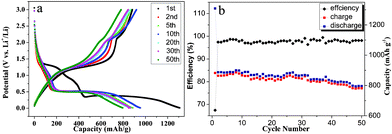 | ||
| Fig. 4 (a) The discharge–charge profiles and (b) cyclic performance of porous Mn2O3 microspheres at a current density of 100 mA g−1 in the voltage range 0.01–3.00 V versus Li+/Li. | ||
The discharge reversible specific capacity of porous Mn2O3 microspheres gradually increases to 900 mA h g−1 at the 8th cycle, corresponding to the activation process associated with the partial crystallinity degradation of the Mn2O3 spheres during initial cycling (Fig. 4b). Then the specific capacity decays very slowly and is maintained above 796 mA h g−1 during 50 cycles at 0.1 C discharge current density, demonstrating the high capacity retention capability of these porous Mn2O3 spheres.
The rate capability of the porous Mn2O3 microspheres was also evaluated at different current densities as shown in Fig. 5. As expected, the specific capacity decreased with current density from ∼900 mA h g−1 at 100 mA g−1 to ∼600 mA h g−1 at 1200 mA g−1. Even at a current density of 2400 mA g−1, the specific capacity was ∼470 mA h g−1, still much higher than the theoretical capacity of graphite (372 mA h g−1). When the current density was decreased from 2400 back to 100 mA g−1, 95% of the initial specific capacity was recovered. This shows that the tested material has capacity retention capability and good rate performance. Such good performance of the Mn2O3 anode material is considered to be caused by its porous structure, reasonable primary particle size, and high crystallinity. This is the first report of such a high rate performance for Mn-based anode materials as far as we know.
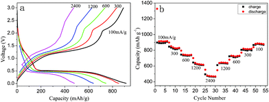 | ||
| Fig. 5 (a) Representative charge and discharge curves and (b) capacity retention of porous Mn2O3 microspheres at various current densities. | ||
The ex-situ XRD analysis was conducted on the electrodes after discharging or charging to the desired voltage (Fig. S3†). After the first discharge to 1.25 V, the peaks of Mn2O3 have already disappeared, with a new broad peak centred at 37.5°(the strongest XRD peak of Mn3O4) appearing, which is attributed to the main peak of Mn3O4. This phase lasts until the discharge capacity is over 410 mA h g−1 (0.38 V), indicating that a new process of lithium insertion has started. This XRD pattern may be ascribed to MnO (a broad peak between 30 and 42°). As the material is discharged to 0.01 V, the XRD pattern becomes very broad, and no obvious XRD peaks can be matched with known crystals. This could be attributed to the nanoparticle nature of the electrochemically-formed species. Similarly, no obvious diffraction peaks can be detected when the material is recharged to 2.10 and 3.00 V after the first cycle. Based on the CV curves, the discharge–charge curves and the ex-situ XRD analysis, the lithium storage mechanism of the synthesized porous Mn2O3 material is suggested as follows:
| 2Li+ + 3Mn2O3 + 2e → 2Mn3O4 + Li2O | (1) |
| 2Li+ + Mn3O4 + 2e → 3MnO + Li2O | (2) |
| 2Li+ + MnO + 2e → Mn + Li2O | (3) |
| Mn + xLi2O ↔ 2xLi+ + MnOx + 2xe (1.0 < x < 1.5) | (4) |
In conclusion, a cheap, scalable and highly reproducible process was developed for the preparation of porous Mn2O3 microspheres. The resulting Mn2O3 microspheres exhibit a good rate capability and highly reversible specific capacity of 796 mAh g−1 at a current density of 100 mA g−1 after 50 cycles. The improved electrochemical performance shows that the synthesized Mn2O3 could be a promising material for a high capacity, low cost, and environmentally friendly anode for LIBs.
This work was supported by the Fundamental Research Funds for the Central Universities (SCUT20120042), by the NNFSC (20801020, 21176045), by the China Postdoctoral Science Foundation (2011M501090), by the Guangdong Province Sci & Tech Bureau (Industry–Education–Research Project, Grant No. 2010B091000004, by the Key Strategic Project, Grant No. 2011B05030008), and by the Fok Ying Tung Foundation (NRC07/08.EG01).
References
- G. J. Jeong, Y. U. Kim, Y. J. Kim and H. J. Sohn, Energy Environ. Sci., 2011, 4, 1986 CAS.
- (a) B. L. Ellis, K. T. Lee and L. F. Nazar, Chem. Mater., 2010, 22, 691 CrossRef CAS; (b) J. M. Tarascon, N. Recham, M. Armand, J. N. Chotard, P. Barpanda, W. Walker and L. Dupont, Chem. Mater., 2010, 22, 724 CrossRef CAS; (c) F. M. Courtel, H. Duncan, Y. Abu-Lebdeh and I. J. Davidson, J. Mater. Chem., 2011, 21, 10206 RSC.
- J. Cabana, l. Monconduit, D. Larcher and R. Palcín, Adv. Mater., 2010, 22, E170 CrossRef CAS.
- (a) W. M. Zhang, X. L. Wu, J. S. Hu, Y. G. Guo and L. J. Wan, Adv. Funct. Mater., 2008, 18, 3941 CrossRef CAS; (b) Z. M. Cui, L. Y. Jiang, W. G. Song and Y. G. Guo, Chem. Mater., 2009, 21, 1162 CrossRef CAS; (c) Y. Z. Piao, H. S. Kim, Y. E. Sung and T. Hyeon, Chem. Commun., 2010, 46, 118 RSC; (d) B. J. Li, H. Q. Cao, J. Shao and M. Z. Qu, Chem. Commun., 2011, 47, 10374 RSC; (e) S. K. Behera, Chem. Commun., 2011, 47, 10373 RSC.
- Y. Y. Yang, Y. Q. Zhao, L. F. Xiao and L. Z. Zhang, Electrochem. Commun., 2008, 10, 1117 CrossRef CAS.
- (a) L. F. Xiao, Y. Y. Yang, J. Yin, Q. Li and L. Z. Zhang, J. Power Sources, 2009, 194, 1089 CrossRef CAS; (b) Y. Ren, A. R. Armsrong, F. Jiao and P. G. Bruce, J. Am. Chem. Soc., 2010, 132, 996 CrossRef CAS; (c) X. F. Fang, X. Lu, X. W. Guo, Y. Mao, Y. S. Hu, J. Z. Wang, Z. X. Wang, F. Wu, H. K. Liu and L. Q. Chen, Electrochem. Commun., 2010, 12, 1520 CrossRef CAS; (d) S. Nayak, S. malik, S. Indris, J. Reedijk and A. K. Powell, Chem.–Eur. J., 2010, 16, 1158 CrossRef CAS; (e) M. Au and T. Admas, J. Mater. Res., 2010, 25, 1656 CrossRef; (f) B. Sun, Z. X. Chen, H. S. Kim, H. Ahn and G. X. Wang, J. Power Sources, 2011, 196, 3346 CrossRef CAS; (g) Y. F. Deng, S. D. Tang, Q. M. Zhang, Z. C. Shi, L. T. Zhang, S. Z. Zhan and G. H. Chen, J. Mater. Chem., 2011, 21, 11987 RSC; (h) J. Gao, M. A. Lowe and H. D. Abruña, Chem. Mater., 2011, 23, 3223 CrossRef CAS; (i) K. F. Zhong, B. Zhang, S.H. Luo, W. Wen, H. Li, X. J. Huang and L. Q. Chen, J. Power Sources, 2011, 196, 6802 CrossRef CAS; (j) F. L. Wang, J. R. Liu, J. Kong, Z. J. Zhang, X. Z. Wang, M. Itoh and K. I. Machida, J. Mater. Chem., 2011, 21, 4314 RSC; (k) Y. C. Qiu, G. L. Xu, K. Y. Yan, H. Sun, J. W. Xiao, S. H. Yang, S. G. Sun, L. M. Jin and H. Deng, J. Mater. Chem., 2011, 21, 6346 RSC; (l) L. Zhou, H. B. Wu, T. Zhu and X. W. Lou, J. Mater. Chem., 2012, 22, 827 RSC.
- H. K. Song, K. T. Lee, M. G. Kim, L. F. Nazar and J. Cho, Adv. Funct. Mater., 2010, 20, 3818 CrossRef CAS.
- J. Liu, T. E. Conry, X. Y. Song, M. M. Doeff and T. J. Richardson, Energy Environ. Sci., 2011, 4, 885 CAS.
- Z. H. Yang, W. X. Zhang, Q. Wang, X. M. Song and Y. T. Qian, Chem. Phys. Lett., 2006, 418, 46 CrossRef CAS.
Footnote |
| † Electronic Supplementary Information (ESI) available: Experimental details. See DOI: 10.1039/c2ra20062g/ |
| This journal is © The Royal Society of Chemistry 2012 |