A highly active hydrazine fuel cell catalyst consisting of a Ni–Fe nanoparticle alloy plated on carbon materials by pulse reversal †
Haidong
Yang
,
Xing
Zhong
,
Zhengping
Dong
,
Jia
Wang
,
Jun
Jin
* and
Jiantai
Ma
*
State Key Laboratory of Applied Organic Chemistry, Lanzhou University, Lanzhou, 730000, P.R. China. E-mail: majiantai@lzu.edu.cn
First published on 28th March 2012
Abstract
A noble metal-free, highly active electrocatalyst for hydrazine fuel cells has been prepared by pulse reversal plating. Plating Ni–Fe alloy on carbon materials (multi-walled carbon nanotubes and graphene) to produce electrocatalysts is facile, rapid, proceeds at low temperature, and does not damage the sp2 hybridization of the carbon support.
As a potential reactor in fuel cells, hydrazine (N2H4) has unique advantages including superior theoretical standard equilibrium potential, high power density and environmentally benign products,1 all of which sparked our interest in developing high-power density direct hydrazine–air fuel cells. Recent efforts to improve performance of catalysts in fuel cells have focused on using noble metal-free catalysts,1,2 adjusting their composition,1 and controlling the size of active metals.3 However, the use of noble metals as catalysts,4 destruction of the sp2 hybridization of the carbon support,5 high temperature treatment and long reaction times4a,6 remain obstacles to wide application of direct alkaline hydrazine fuel cell anodes. Meanwhile, because of the excellent properties of carbon materials such as multi-walled carbon nanotubes (MWCNTs) and graphene in many engineering applications,7 the preparation of high-quality carbon-based materials for use as electrocatalysts in fuel cells has been explored in recent years.8
In this paper, we present a facile, environmentally friendly, noble metal-free pulse reversal plating method (detailed information is presented in the supporting information†) for the arge scale production of Ni–Fe nanoparticle alloys using the inexpensive materials NiSO4·6H2O and FeSO4·7H2O as reagents. The process of Ni–Fe nanoparticles deposited on the carbon material is shown in Scheme 1. This approach can completely avoid damaging the sp2 hybridization of the carbon materials, allowing the catalyst to exhibit high activity.
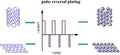 | ||
| Scheme 1 Schematic representation of the experimental procedure for plating Ni–Fe alloy on MWCNTs and graphene. | ||
Carbon-supported Ni–Fe alloy catalysts with stoichiometries from (95![[thin space (1/6-em)]](https://www.rsc.org/images/entities/char_2009.gif) :
:![[thin space (1/6-em)]](https://www.rsc.org/images/entities/char_2009.gif) 5) to (50
5) to (50![[thin space (1/6-em)]](https://www.rsc.org/images/entities/char_2009.gif) :
:![[thin space (1/6-em)]](https://www.rsc.org/images/entities/char_2009.gif) 50) were obtained by pulse reversal plating to determine the optimum content for hydrazine electrocatalysis. Briefly, the carbon material (10 mg) was combined with deionized water (5.0 mL), ethanol (2.5 mL) and Nafion solution (2.5 mL, 0.5 wt%) and then sonicated for 20 min. The ink (10 μL) was applied onto a glassy carbon electrode, left to dry for 10 min under an infrared light and then immersed in a plating solution for 2 min before plating. Ni–Fe alloy catalysts were prepared by pulse reversal plating using a method nearly identical to those previously published.9 The compositions of the plating solutions and conditions10 are listed in Table S1 and S2.† After electrodeposition of the Ni–Fe alloy on the carbon material, cyclic voltammograms (CVs) of the samples were obtained in Ar-saturated 0.1 M hydrazine hydrate–0.015 M KOH–1 M NaCl solution (60% v/v hydrazine hydrate). The catalyst samples (pure Ni, pure Fe, and compositions from Ni55Fe45 to Ni95Fe5) were tested from −1.3 V to −0.20 V (vs. RHE) at 20 mV s−1, and then cycled 500 times to test the durability of the electrode under these conditions. The electrocatalytic performance was normalized by the mass activity of the Ni–Fe alloy. The total weight of metal can be calculated using the following two equations
50) were obtained by pulse reversal plating to determine the optimum content for hydrazine electrocatalysis. Briefly, the carbon material (10 mg) was combined with deionized water (5.0 mL), ethanol (2.5 mL) and Nafion solution (2.5 mL, 0.5 wt%) and then sonicated for 20 min. The ink (10 μL) was applied onto a glassy carbon electrode, left to dry for 10 min under an infrared light and then immersed in a plating solution for 2 min before plating. Ni–Fe alloy catalysts were prepared by pulse reversal plating using a method nearly identical to those previously published.9 The compositions of the plating solutions and conditions10 are listed in Table S1 and S2.† After electrodeposition of the Ni–Fe alloy on the carbon material, cyclic voltammograms (CVs) of the samples were obtained in Ar-saturated 0.1 M hydrazine hydrate–0.015 M KOH–1 M NaCl solution (60% v/v hydrazine hydrate). The catalyst samples (pure Ni, pure Fe, and compositions from Ni55Fe45 to Ni95Fe5) were tested from −1.3 V to −0.20 V (vs. RHE) at 20 mV s−1, and then cycled 500 times to test the durability of the electrode under these conditions. The electrocatalytic performance was normalized by the mass activity of the Ni–Fe alloy. The total weight of metal can be calculated using the following two equations
| MNiFe = [(Q/2F) × 58.73] × 31.6% |
| MNiFe = [(Q/2F) × 58.73] × 20.1% |
When the MWCNTs act as the support, the Ni85Fe15 alloy is more active than other compositions (Fig. 1a). The current of the hydrazine hydrate oxidation peak for Ni85Fe15 was higher than that on a pure Ni electrode. No hydrazine oxidation was observed when pure Fe was used as the electrode. As the iron content was increased, the catalytic activity of nanoparticles first increased and then decreased. This shows that nickel plays the major active role in the oxidation of hydrazine, while iron plays a synergistic one. As the iron content was increased, cooperation effects also increased. However, if the content of iron is too much, there are not enough major catalysts (nickel). Experiments show that Ni85Fe15 is the best catalyst for hydrazine oxidation.
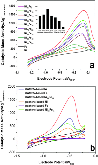 | ||
| Fig. 1 (a) Evaluation of hydrazine electrooxidation activities of Ni–Fe bimetallic catalysts (MWCNTs-based) compared to Ni and Fe (MWCNTs-based) references. Anodic voltammetric sweeps after 500 cycles between −1.30 V and −0.20 V are shown. Conditions: 0.1 M hydrazine hydrate–0.015 M KOH–1 M NaCl, 60 °C, 20 mV s−1. Inset: mass activities at respective peaks. (b) CVs of MWCNTs-based Ni, MWCNTs-based Fe, MWCNTs-based Ni85Fe15, graphene-based Ni, graphene-based Fe, and graphene-based Ni85Fe15 electrocatalysts in 0.1 M hydrazine hydrate–0.015 M KOH–1 M NaCl solution, 60 °C, 20 mV s−1. The metal mass-based catalytic current is plotted. | ||
Fig. 1b compares the CV scans obtained for the 500th cycle of the oxidation of hydrazine hydrate by the series of MWCNT-based (Ni, Fe, Ni85Fe15) and graphene-based (Ni, Fe, Ni85Fe15) catalysts. The figure shows that with either MWCNT or graphene as the support, nickel is the major active catalyst in the oxidation of hydrazine hydrate, while iron is the synergistic one. The catalytic activity of MWCNT-based Ni–Fe nanoparticles is higher than the graphene-based one, and the cause of this phenomenon needs further exploration. The onset oxidation of hydrazine hydrate on Ni–Fe alloy is around −0.8 V and a large oxidation peak was observed at −0.45 V. The high catalytic activity of MWCNT- and graphene-based Ni–Fe nanoparticles is a result of their high surface area, and thorough dispersion on the carbon electrode. In addition, the pulse reversal plating method does not reduce the conductivity of the carbon material because it does not destroy the sp2 hybridization of the carbon material (Fig. 3b).
TEM images of graphene- and MWCNT-based catalysts are shown in Fig. 2. The Ni–Fe nanoparticles possessed a size distribution between 10 and 15 nm. Fig. 3a shows XRD patterns of MWCNT-based and graphene-based Ni–Fe nanoparticle samples. Both patterns have three peaks (nearly 43.2°, 52.2° and 75.5°) that appear, indicating all Ni–Fe nanoparticles were face-centered cubic (space group Fm-3m) substitutional solid solutions (disordered alloys). The compositions of the most active catalysts derived from inductively coupled plasma spectra (ICP) are summarized in Table S3,† showing that their actual and nominal compositions are consistent.
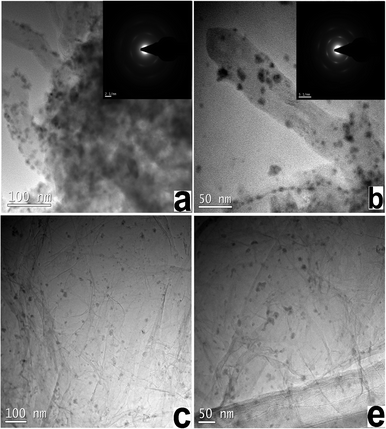 | ||
| Fig. 2 TEM images of (a), and (b) MWCNT-based Ni–Fe nanoparticles, and (c), and (d) graphene-based Ni–Fe nanoparticles. | ||
Fig. 3b shows the Raman spectra of a single-layer of graphene and MWCNT samples before and after plating. After the plating, the D band and G band did not significantly change in either its width or shape. As the Ni–Fe nanoparticle was plated on the carbon material, the I(D)![[thin space (1/6-em)]](https://www.rsc.org/images/entities/char_2009.gif) :
:![[thin space (1/6-em)]](https://www.rsc.org/images/entities/char_2009.gif) I(G) ratio increases monotonically from a low of 1.0 ± 0.1 for graphene to 1.1 ± 0.1 for graphene-based Ni–Fe nanoparticles, the I(D)
I(G) ratio increases monotonically from a low of 1.0 ± 0.1 for graphene to 1.1 ± 0.1 for graphene-based Ni–Fe nanoparticles, the I(D)![[thin space (1/6-em)]](https://www.rsc.org/images/entities/char_2009.gif) :
:![[thin space (1/6-em)]](https://www.rsc.org/images/entities/char_2009.gif) I(G) ratio of MWCNTs was maintained at 1.1 ± 0.1. This suggests that the sp2 carbon network of graphene and MWCNTs was not damaged by plating, so the carbon support should retain its good electrical conductivity.
I(G) ratio of MWCNTs was maintained at 1.1 ± 0.1. This suggests that the sp2 carbon network of graphene and MWCNTs was not damaged by plating, so the carbon support should retain its good electrical conductivity.
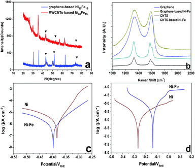 | ||
| Fig. 3 (a) XRD pattern of Ni–Fe alloy (MWCNTs-based and graphene-based), (b) Raman spectra of MWCNTs and graphene before and after plating, (c) Tafel curves of pure Ni and Ni85Fe15 alloy in 3.5 wt% NaCl electrolyte, (d) Tafel curves of pure Ni and Ni85Fe15 alloy in 0.7 M NaCl–0.015 M NaOH electrolyte. | ||
The Tafel behavior of the pure Ni and Ni85Fe15 alloy in 3.5 wt% NaCl and 0.7 M NaCl–0.015 M NaOH electrolyte is shown in Fig. 3c and d, respectively. In 3.5 wt% NaCl, Ecorr/V of Ni85Fe15 is lower than that of pure Ni, but in 0.7 M NaCl–0.015 M NaOH, Ecorr/V of Ni85Fe15 is higher than that of pure Ni. This indicates that the Ni85Fe15 alloy and pure Ni have the same corrosion resistance.
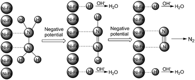
The following mechanism for the Ni85Fe15 nanoparticles with superior electrocatalytic activity towards hydrazine electrooxidation is proposed, see Scheme 2. Initially, the two N atoms of N2H4 coordinate with a Ni85Fe15 nanoparticle to form N(ad). As the potential gradually changes from positive to negative, the surface of the Ni85Fe15 nanoparticle becomes electron-rich, which repels nitrogen atoms and attracts hydrogen atoms. Each of the two H–N bonds breaks, so H becomes adsorbed on the metal surface, forming H(ad). Subsequently, H(ad) reacts with OH− to form H2O and an electron. Finally, N2 forms between the two residual N(ad) of the original hydrazine molecule. Throughout the process, nickel is the major active catalyst, which leads to the oxidation of hydrazine. As a synergistic dopant, iron significantly promotes the catalytic effect. With iron added to the nickel catalysts, the number of active sites increased, and this feature might contribute to enhance the catalytic activity.
In conclusion, Ni85Fe15 nanoparticles were plated on MWCNTs and graphene using a pulse reversal plating method. These carbon material-based Ni85Fe15 alloy catalysts possess superior electrocatalytic activity for hydrazine electrooxidation, making them attractive for use as direct alkaline hydrazine fuel cell anodes. The fabrication of these catalysts is simple, fast, and does not affect the electrical conductivity of the carbon support. In our experiment, the cost of the catalyst was minimized by using 15 wt% Fe. The corrosion resistance of the Ni85Fe15 alloy was high, making it stable for long term storage and transport.
This research is supported by the Natural Science Foundation of Gansu (No. 1010RJZA218) and the Fundamental Research Funds for the Central Universities (lzujbky-2010-33).
References
- J. Sanabria-Chinchilla, K. Asazawa, T. Sakamoto, K. Yamada, H. Tanaka and P. Strasser, J. Am. Chem. Soc., 2011, 133, 5425–5431 CrossRef CAS.
- T. Sakamoto, K. Asazawa, K. Yamada and H. Tanaka, Catal. Today, 2011, 164, 181–185 CrossRef CAS.
- G. W. Yang, G. Y. Gao, C. Wang, C. L. Xu and H. L. Li, Carbon, 2008, 46, 747–752 CrossRef CAS.
- (a) Q. F. Yi and W. Q. Yu, J. Electroanal. Chem., 2009, 633, 159–164 CrossRef CAS; (b) K. Yamada, K. Yasuda, N. Fujiwara, Z. Siroma, H. Tanaka, Y. Miyazaki and T. Kobayashi, Electrochem. Commun., 2003, 5, 892–896 CrossRef CAS; (c) Y. Liang, Y. Zhou, J. Ma, J. Y. Zhao, Y. Chen, Y. W. Tang and T. H. Lu, Appl. Catal., B, 2011, 103, 388–396 CrossRef CAS.
- D. J. Guo and H. L. Li, Electrochem. Commun., 2004, 6, 999–1003 CrossRef CAS.
- B. Dong, B. L. He, Y. M. Chai and C. G. Liu, Mater. Chem. Phys., 2010, 120, 404–408 CrossRef CAS.
- (a) M. J. Allen, V. C. Tung and R. B. Kaner, Chem. Rev., 2010, 110, 132–145 CrossRef CAS; (b) D. Eder, Chem. Rev., 2010, 110, 1348–1385 CrossRef CAS; (c) L. B. Hu, D. S. Hecht and G. Gruner, Chem. Rev., 2010, 110, 5790–5844 CrossRef CAS; (d) N. Karousis, N. Tagmatarchis and D. Tasis, Chem. Rev., 2010, 110, 5366–5397 CrossRef CAS.
- (a) G. Y. Gao, D. J. Guo, C. Wang and H. L. Li, Electrochem. Commun., 2007, 9, 1582–1586 CrossRef CAS; (b) M. Pumera and H. Iwai, J. Phys. Chem. C, 2009, 113, 4401–4405 CrossRef CAS.
- (a) A. Bai and C. C. Hu, Electrochim. Acta, 2005, 50, 1335–1345 CrossRef CAS; (b) J. Y. Fei and G. D. Wilcox, Electrochim. Acta, 2005, 50, 2693–2698 CrossRef CAS; (c) P. T. Tang, Electrochim. Acta, 2001, 47, 61–66 CrossRef CAS.
- (a) T. E. Buchheit, S. H. Goods, P. G. Kotula and P. F. Hlava, Mater. Sci. Eng., A, 2006, 432, 149–157 CrossRef; (b) S. H. Kim, H. J. Sohn, Y. C. Joo, Y. W. Kim, T. H. Yim, H. Y. Lee and T. Kang, Surf. Coat. Technol., 2005, 199, 43–48 CrossRef CAS.
Footnote |
| † Electronic Supplementary Information (ESI) available: The detail of pulse reversal plating. Nickel iron plating chemistry and bath conditions. ICP test data. See DOI: 10.1039/c2ra01346k/ |
| This journal is © The Royal Society of Chemistry 2012 |

