Phase-separated binary polymers spin coated onto microwrinkles
Takuya
Ohzono
*a and
Hiroyuki
Kitahata
bc
aNanosystem Research Institute, National Institute of Advanced Industrial Science and Technology (AIST), 1-1-1 Higashi, Tsukuba, 305-8565, Japan. E-mail: ohzono-takuya@aist.go.jp
bDepartment of Physics, Graduate School of Science, Chiba University, 1-33 Yayoi-cho, Inage-ku, Chiba, 263-8522, Japan
cPRESTO, JST, 4-1-8, Honcho, Kawaguchi, 332-0012, Japan
First published on 1st February 2012
Abstract
We report the fabrication of topographically guided phase-separated structures of a binary polymer mixture of polystyrene (PS) and poly(2-vinylpyridine) (PVP) spin coated onto sinusoidal microgrooves. Depending on the polymer concentration, dewetted PS islands or uniform PS ribbons were formed in the microgrooves, which were supported by an underlayer of PVP. Uniform PS ribbons were not obtained by sequential coating of the polymers. Tuning the polymer concentration with an appropriate solvent and substrate topography makes this method of spin coating onto microwrinkles a simple, low-cost method for fabricating various topography-guided polymer morphologies.
Introduction
Spontaneously formed spatial structures1 on nanometre and micrometre scales have become important in low-cost fabrication processes for many potential technological applications, such as photonics, electronics, and surfaces with controlled wettability and tribology. Microwrinkled surfaces are a promising type of structure, which are formed on the surface of a compliant substrate covered with a hard, thin film under lateral compressive strain.2–6 Areas of microwrinkles measuring tens of square centimetres can be fabricated easily and various functional materials can be used as the thin film. Microwrinkles have therefore been studied extensively during the last decade for various possible applications.7–11 The microgrooves within microwrinkles have been used in the low-cost fabrication of micropatterns as templates for colloidal assembly,12,13polymer patterning,14 and selective colloidal coating.15A key factor for making use of the topographic pattern is the interaction between the surface undulation and the liquid that contains a solute or a melt of interest. We have found that the contact angle and the aspect ratio of the undulation are the critical parameters for sinusoidal grooves to allow the introduction of liquids into only the microwrinkle grooves under quasi-static conditions.10 In contrast, during a non-equilibrium process, such as solvent evaporation or a chemical reaction, the general conditions are difficult to determine for patterning the liquid in the grooves. For example, during fast solvent evaporation after spin coating a polymer solution onto the microgrooves, the relaxation toward equilibrium is hindered by kinetic barriers in the quenched states. Nonetheless, non-equilibrium processes have often been used in engineering16 and sometimes result in a variety of patterns through self-organization under non-equilibrium conditions.17,18
In this paper, we examine the phase-separated morphology of binary polymers on microwrinkle grooves, which are formed during fast solvent evaporation after spin coating.19 To focus on the effect of the substrate topography, the well-studied polystyrene (PS) and poly(2-vinylpyridine) (PVP) system was used, which shows clear phase separation (demixing) after solvent evaporation from a 1![[thin space (1/6-em)]](https://www.rsc.org/images/entities/char_2009.gif) :1 (w/w) solution mixture.20 For this binary system, it has been reported that chemical patterns fabricated on a flat substrate by conventional lithography can guide the phase-separated morphology.20 However, little is known about the guiding effect of surface topographic patterns.21 We investigated the effect of polymer concentration on the phase-separated morphology in sinusoidal grooves. The results were compared with the patterns obtained by spin coating a solution of each single polymer component, in order to discuss the phase separation process during solvent evaporation. Under specific conditions, uniform peelable PS ribbons formed along the grooves, which were supported by the PVP underlayer. This structure was not obtained using the sequential spin coating of each individual polymer. This process can achieve the low-cost microfabrication of length-controlled polymeric microribbons without the use of conventional lithography.
:1 (w/w) solution mixture.20 For this binary system, it has been reported that chemical patterns fabricated on a flat substrate by conventional lithography can guide the phase-separated morphology.20 However, little is known about the guiding effect of surface topographic patterns.21 We investigated the effect of polymer concentration on the phase-separated morphology in sinusoidal grooves. The results were compared with the patterns obtained by spin coating a solution of each single polymer component, in order to discuss the phase separation process during solvent evaporation. Under specific conditions, uniform peelable PS ribbons formed along the grooves, which were supported by the PVP underlayer. This structure was not obtained using the sequential spin coating of each individual polymer. This process can achieve the low-cost microfabrication of length-controlled polymeric microribbons without the use of conventional lithography.
Experimental procedure
Microwrinkles with shallow, straight microgrooves, a spatial wavelength of 4.1 ± 0.1 μm and a depth of 0.6 ± 0.03 μm were prepared by the method reported by Ohzono et al.10 The top hard layer was polyimide (PI), which was imidized from a polyamic acid (poly(pyromellitic dianhydride-co-4,4′-oxydianiline, Sigma-Aldrich). The tetrahydrofuran (THF, Sigma-Aldrich) solutions of PS (averaged Mw = 90000, Sigma-Aldrich), PVP (averaged Mw = 121500, Sigma-Aldrich), and a 1:1 mixture of the two polymers were spin coated at 5 krpm for 60 s onto the microwrinkles (MSA-150, Mikasa). Each polymer concentration was varied from 0.25 to 1.5 wt%. The structures were observed with an optical microscope in reflection mode (BX-51, Olympus) and an atomic force microscope (AFM, 5400, Agilent) in tapping mode. For the binary system, one of the components was removed by rinsing the sample with a selective solvent to investigate the phase-separated structure; cyclohexane was used to remove PS and ethanol was used for PVP. The figures are oriented so that the y axis corresponds to the groove direction and the z axis is normal to the wrinkle surface.
Results and discussion
Fig. 1(a)–1(g) shows the morphologies of concentration-dependent PS patterns on microwrinkles and their dewetted domains after spin coating single PS component solutions. At lower concentrations, droplet-like PS islands appeared at around the groove center. As the concentration increased, the groove was filled with the PS phase, and dewetted holes appeared at the center and edges of the groove. PS never appeared at the crest of the wrinkles in the concentration range used in this study. Spin coating a THF solution containing a single PS component did not produce a uniform pattern lacking dewetted hole defects.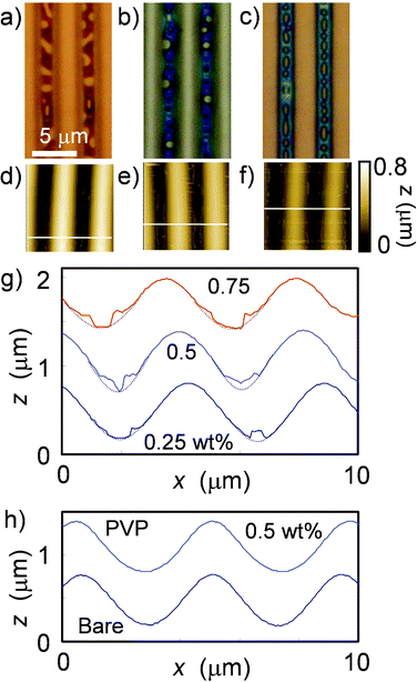 | ||
| Fig. 1 Morphologies of polymer spin coated from a single component solution on microwrinkles. Optical images of PS-coated samples with (a) 0.25, (b) 0.5, and (c) 0.75 wt% THF solution. The blue areas are PS phases. (d)–(f) Corresponding AFM images (102 μm2). (g) Corresponding cross sectional profiles, indicated by white lines in (d)–(f). The profiles of the bare groove surface are intended as a rough guide. (h) Cross sectional profiles of the bare microwrinkle and PVP-coated sample with 0.5 wt% THF solution. Because PVP-coated samples of other concentrations are also smooth and sinusoidal, the images are omitted here. | ||
In contrast, PVP uniformly coated the surface at any concentration. The AFM profile in Fig. 1(h) is smooth, sinusoidal and slightly deeper than for PS, although it is within the error range. The results indicate that the affinity of concentrated PVP solutions was higher than that of PS for the PI microwrinkle surface. This means that the effective spreading parameter, S = γSO − (γSL − γ), of the concentrated PS/THF on PI is negative (partial wetting) and that of the concentrated PVP/THF on PI is positive (complete wetting), where the coefficients γSO, γSL, and γ are the interfacial tensions at the PI/vapor, PI/solution, and solution/vapor interfaces, respectively. Because the PVP pyridine substituent is more polar than the PS benzyl substituent, this may explain the higher affinity between PVP and the PI surface, which also has polar imide groups. This polar interaction should reduce γSL.
Fig. 2(a)–2(g) shows phase-separated patterns for the PS/PVP blend system. At lower polymer concentrations, the PS islands only appeared in the grooves and were surrounded by a sea of PVP. The PS islands joined together as the concentration increased, which was similar to the behavior observed for single PS coating. However, the fused PS islands filled the grooves without creating dewetted holes; uniform PS ribbons were formed over a PVP layer in the grooves. A schematic for the cross-sectional profile is shown in Fig. 2(h), which was constructed using the AFM images of the samples after selective rinsing (Fig. 2(i)–2(k)). Some PS ribbons peeled away from the grooves after rinsing with ethanol, which selectively removes PVP (Fig. 2(m)–2(p)). The thickness of the PS ribbon was 110 ± 20 nm for the sample coated with the 1.5 wt% binary polymer solution. Casting the ethanol dispersion of the peeled PS ribbons onto a glass substrate confirmed that the PS ribbons were transferred onto the surface after solvent evaporation (Fig. 2(n)).
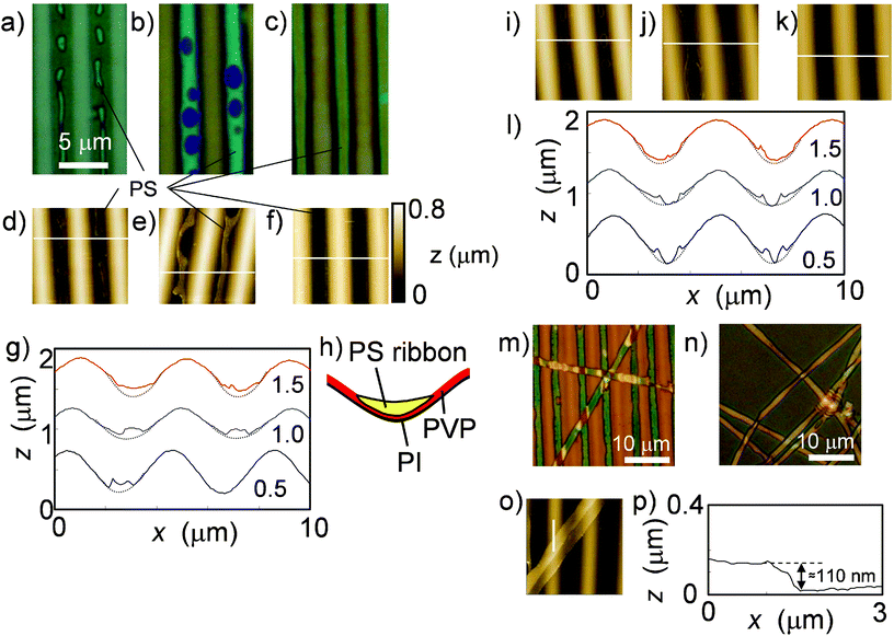 | ||
| Fig. 2 Morphologies of phase-separated polymers spin coated from binary solution on microwrinkles. Optical images of PS/PVP-coated samples with (a) 0.5, (b) 1.0, and (c) 1.5 wt% THF solution. (d)–(f) Corresponding AFM images (102 μm2). (g) Corresponding cross sectional profiles, indicated by white lines in (d)–(f). The profiles of the bare groove surface are a visual guide. (h) A schematic for the cross section of the state with PS ribbons on the PVP underlayer shown in (c) and (f). (i)–(k) Corresponding AFM images (102 μm2) of the samples after a selective rinse using cyclohexane that removes PS parts. (l) Corresponding cross sectional profiles of samples with PS removed, indicated by white lines in (i)–(k). (m) Optical images of the sample shown in (c) and (f) after a selective rinse using ethanol, and (n) the peeled PS ribbons transferred onto a slide glass. (o) An AFM image and (p) the profile corresponding to the sample shown in (m). The vertical white line in (o) indicates the position of the profile shown in (p). | ||
For comparison, a PS cyclohexane solution (0.75 wt%) was spin coated onto a microwrinkle surface pre-coated with a PVP THF solution (0.25 wt%). The PS accumulated in the grooves, although there were large, rough, dewetted patches (Fig. 3). This morphology contrasts sharply with the uniform PS ribbons obtained using the binary solution instead of sequential coating.
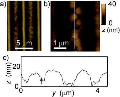 | ||
| Fig. 3 Dewetted morphology of PS in a microwrinkle groove pre-coated with PVP. (a) Optical, (b) AFM images, and (c) the corresponding profile along the groove direction, indicated by the white line in (b). | ||
Next, the formation of the phase-separated structure after spin coating using the binary polymer solution is qualitatively discussed. As the solvent evaporates, the surface of the solution reaches the crest of the wrinkle, and leaves the concentrated binary polymer solution in the groove. The phase separation must occur after this point in order to induce a microgroove guiding effect on the polymer morphology. Otherwise, the guiding effect would be weakened, because highly viscous phase-separated domains are not readily mobile and deformable in response to the shallow topography. The concentration range in this study is likely to fulfill the conditions for topographic guidance to occur. In general, the polymer concentration and the size of the sinusoidal grooves must also be adjusted to meet these conditions.
The transient PVP-rich liquid wets the PI surface because of the positive effective S, which means PVP coats the microwrinkle from the top of the wrinkle crest as solvent evaporation decreases the liquid level. Thus, the PS is concentrated in the groove. From this situation, the phase separation occurs at a critical polymer concentration, although the details of the demixing process are difficult to clarify due to the nonequilibrium spatiotemporal gradients in the polymer concentration and temperature. Because PVP favors the PI surface, it is assumed that a phase-separated layered structure, air/PS-rich/PVP-rich/PI, is formed. The average thickness of the PS layer should be proportional to the total concentration. At higher concentrations, a uniform PS-rich layer forms, indicating that the layer is stable during the solvent evaporation. In contrast, a uniform PS layer is not formed at lower PS concentrations, suggesting that the thin PS-rich layer becomes unstable during solvent evaporation.
Because the PS-rich layer is hundreds of nanometres thick, this phenomenon may be explained by spinodal dewetting.22–24 If we consider a simple general case of spinodal dewetting,25 where the thickness-dependent energy F(h) (h: thickness) is described by the van der Waals forces between the layer and the underlayer, and gravity, then F(h) ∝ A/h2 + ch2, where A is the interfacial Hamaker constant and c is a constant related to gravity. When A < 0, a fluid layer with a small h becomes unstable because d2F/dh2 < 0, which results in spinodal dewetting; the small thickness fluctuations in the layer are amplified. Typically, the critical thickness is in the range of tens of nanometres. The sign of the effective A in this case should be negative, although it is difficult to estimate the true value of A for this system from material parameters such as polarizability, because of the transient complex mixture of polymers and the gradients of materials and temperature present in the solvent. However, similar dewetting of a top polymer layer during solvent evaporation has been reported for spin coated binary polymers of PS and polymethylmethacrylate.19
The critical thickness is also difficult to determine for the dewetting of the PS-rich layer on the PVP-rich layer because of the fast solvent evaporation. The speed of relaxation towards equilibrium rapidly decreases, and the system is quenched. The changes in concentration affect both the effective surface energy and the viscosity, both of which can alter the quenched final morphology. This is the main difficulty in controlling the final phase-separated structure through the non-equilibrium process; a uniform polymer film that fills only the groove is not consistently formed. In contrast, a nontrivial structure may be obtained by changing the distance from the quasi-static process,17,18 for example, the evaporation speed might be a measure of the distance. Further control of the morphology could be achieved by post thermal annealing or exposure to the saturated vapor of a good solvent.14
The dewetted structure observed after the sequential coating of the PVP pre-coated microwrinkles with PS indicates that a thin layer of the concentrated cyclohexane PS solution is unstable on the PVP surface (Fig. 3). This is rather reasonable because PVP is miscible with neither cyclohexane nor PS, which can be understood in terms of an equilibrium state. In contrast, the PS ribbon obtained from the binary solution should be a quenched structure on the demixing process, which cannot be expected naively from an argument of an equilibrium state. Therefore, PS on PVP can be either uniform or non-uniform depending on the formation process (one-shot or sequential coating) and the solvents; various combinations have potential for producing useful quenched phase-separated structures.
The peelable PS ribbon created in this study is a novel structure, which cannot be obtained by any other method than the spin coating of the binary polymer solution. Because microwrinkle grooves are easily prepared, the mass production of PS ribbons is possible. These nanometre scale polymer ribbons represent an intriguing new class of nanoscale objects.
Conclusions
We have reported an example of microtopography-guided phase separation of binary polymer blends. Tuning the polymer concentration with an appropriate solvent and substrate topography makes this method of spin coating onto microwrinkles a simple, low cost method for fabricating various topography-guided polymer morphologies. PS ribbons, which were not obtained from the sequential process, could be formed. This process is a good example of a microfabrication method using an easily prepared self-organized structure26 and a highly non-equilibrium process. Although the precise mechanism is difficult to clarify, the concept of using non-equilibrium processes for creating a new structure is likely to be important in future nano-microfabrication, because these strategies are often found in biological systems.Acknowledgements
TO thanks H. Morita and T. Yamaguchi for fruitful comments. This work was partially carried out under the auspices of the New Energy and Industrial Technology Department Organization (NEDO) of Japan under the Industrial Technology Research Grant Program in 2008 and Grants-in-Aid (KAKENHI) for Young Scientists (B).References
- P. Ball, The Self-Made Tapestry, Oxford Univ. Press, 2001 Search PubMed.
- J. Genzer and J. Groenewold, Soft Matter, 2006, 2, 310 RSC.
- N. Bowden, S. Brittain, A. G. Evans, J. W. Hutchinson and G. M. Whitesides, Nature, 1998, 393, 146 CrossRef CAS.
- P. J. Yoo, K. Y. Suh, S. Y. Park and H. H. Lee, Adv. Mater., 2002, 14, 1383 CrossRef CAS.
- S. P. Lacour, S. Wagner, Z. Huang and Z. Suo, Appl. Phys. Lett., 2003, 82, 2404 CrossRef CAS.
- T. Ohzono and M. Shimomura, Phys. Rev. B, 2004, 69, 132202 CrossRef.
- C. M. Stafford, Nat. Mater., 2004, 3, 545 CrossRef CAS.
- E. P. Chan, E. J. Smith, R. C. Hayward and A. J. Crosby, Adv. Mater., 2008, 20, 711 CrossRef CAS.
- T. Ohzono, H. Watanabe, R. Vendamme, C. Kamaga, T. Kunitake, T. Ishihara and M. Shimomura, Adv. Mater., 2007, 19, 3229 CrossRef CAS.
- T. Ohzono, H. Monobe, K. Shiokawa, M. Fujiwara and Y. Shimizu, Soft Matter, 2009, 5, 4658 RSC.
- T. Ohzono and H. Monobe, Langmuir, 2010, 26, 6127 CrossRef CAS.
- K. Efimenko, M. Rackaitis, E. Manias, A. Vaziri, L. Mahadevan and J. Genzer, Nat. Mater., 2005, 4, 293 CrossRef CAS.
- C. Lu, H. Möhwald and A. Fery, Soft Matter, 2007, 3, 1530 RSC.
- D. C. Hyun, G. D. Moon, C. J. Park, B. S. Kim, Y. Xia and U. Jeong, Adv. Mater., 2010, 22, 2642 CrossRef CAS.
- S. Yang, K. Khare and P.-C. Lin, Adv. Funct. Mater., 2010, 20, 2550 CrossRef CAS.
- H. Shimizu, S. Horiuchi and T. Kitano, Macromolecules, 1999, 32, 537 CrossRef CAS.
- G. Nicolis and I. Prigogine, Self-organization in nonequilibrium systems, John Wiley & Sons, New York, 1977 Search PubMed.
- T. Yamaguchi, I. R. Epstein, M. Shimomura and T. Kunitake, Chaos, 2005, 15, 047501 CrossRef.
- S. Walheim, M. Boltau, J. Mlynek, G. Krausch and U. Steiner, Macromolecules, 1997, 30, 4995 CrossRef CAS.
- M. Boltau, S. Walheim, J. Mlynek, G. Krausch and U. Steiner, Nature, 1998, 391, 877 CrossRef CAS.
- J. H. Wei, D. C. Coffey and D. S. Ginger, J. Phys. Chem. B, 2006, 110, 24324 CrossRef CAS.
- R. L. A. Jones, L. J. Norton, E. J. Kramer, F. S. Bates and P. Wiltzius, Phys. Rev. Lett., 1991, 66, 1326 CrossRef CAS.
- G. Reiter, Phys. Rev. Lett., 1992, 68, 75 CrossRef CAS.
- W. Straub, F. Bruder, R. Brenn, G. Krausch, H. Bielefeldt, A. Kirsch, O. Marti, J. Mlynek and J. F. Marko, Europhys. Lett., 1995, 29, 353 CrossRef CAS.
- P. G. de Gennes, F. Brochard-Wyart and D. Quere, Capillarity and Wetting Phenomena; Drops, Bubbles, Pearls, Waves, Springer, 2004 Search PubMed.
- T. Ohzono and H. Monobe, J. Colloid Interface Sci., 2012, 368, 1 CrossRef CAS.
| This journal is © The Royal Society of Chemistry 2012 |