Changes in morphological and nano-mechanical properties of the milk fat globule membrane during processing
Thakshila S.
Balasuriya
a,
Lydia
Ong
ab,
Sally L.
Gras
*ab and
Raymond R.
Dagastine
*ac
aParticulate Fluids Processing Centre, Department of Chemical & Biomolecular Engineering, The University of Melbourne, Parkville, Vic 3010, Australia. Fax: +61 3 8344 4153; Tel: +61 3 8344 4704E-mail: rrd@unimelb.edu.au
bThe Bio21 Molecular Science & Biotechnology Institute, The University of Melbourne, Parkville, Vic 3010, Australia. Tel: +61 3 8344 2259/6281E-mail: sgras@unimelb.edu.au
cMelbourne Centre for Nanofabrication, 151 Wellington Road,, Clayton, 3168, Australia
First published on 31st January 2012
Abstract
The milk fat globule membrane (MFGM) is a complex soft matter system that encapsulates the milk fat globule (MFG). It is important for the successful delivery of nutrients for newborns and it is also increasingly studied for its potential pharmaceutical benefits. Yet, the persistence and integrity of the MFGM through many steps common in the processing of milk for consumption and cheese manufacture is not completely understood and is an area of ongoing interest. In this study, atomic force microscopy (AFM) was used to characterize the MFGM membrane interface to demonstrate the effects of mechanical force and shear encountered during milk processing. The results showed that significant differences can be observed and such a soft biological system with complex constituents can be quantitatively characterized using AFM. Major differences were observed in the surface morphology and the roughness of the MFGM in raw milk, raw ultra filtrate (UF) retentate, homogenized milk, cheese milk and cream samples. The MFGM of the homogenized fat globules showed the greatest difference in appearance when compared to the native raw MFGM from damage largely due to the homogenization process. In addition, AFM elasticity and thickness measurements of the MFGM showed quantitative differences between the five different samples with an increase in the stiffness of the MFGM of milk samples that have undergone more processing steps. The quantitative results of the physical nature of the MFGM from the AFM study, combined with the qualitative results on the chemical nature of the MFGM, demonstrate that AFM can aid in the understanding of the interfacial behaviour of complex soft matter systems where access to detailed chemical composition is limited.
1 Introduction
As a soft matter system, milk is a complex mixture of primarily three materials: milk fat globules (MFG), casein micelles and serum proteins. Each material is in itself a multi-component mixture with a specific purpose and function. For example, the stability of MFGs against coalescence is controlled by the milk fat globule membrane (MFGM) surrounding the globule, which acts as a stabilizer. In the context of food science and engineering, the MFGs deliver the nutrition required for newborn growth and development. The MFG is important for consumer sensory perceptions and the MFGM is important for potential nutritional and pharmaceutical benefits derived from its various constituents, such as, sphingomyelin, a type of phospholipid found in the MFGM.1 Thus, the dairy community is interested in studying the effect of various milk processing steps on the integrity of the MFG and MFGM in homogenized and standardized consumer milk preparations. The integrity of the MFGM will also impact on milk products such as cheese or yogurt. Thus, the industry is interested in understanding the effect of various processing steps to minimize damage to the MFG and MFGM, in order to improve sensory perceptions and preserve maximum nutritional value.Here, we have chosen to study the MFG particularly because it is a biological soft matter system that offers complexity at the interface. We have used atomic force microscopy (AFM) to study the MFGM that surrounds the milk globule with the aim of further understanding the physical nature of the MFGM where quantitative chemical composition at the interface is difficult to obtain via bulk analysis methods.
Such bulk analysis techniques to study the composition of milk include analyzing the different membrane constituents such as phospholipids, fatty acids or proteins using various solvent extractions and chromatography.2,3 The fat globule size distribution has been examined using optical microscopy, laser light scattering and turbidity measurements, and rheological measurements have been used to determine the effect of industrial processing on the MFGM.2 More recently, confocal laser scanning microscopy (CLSM) has become a highly successful technique for studying the MFGM via the use of fluorescent dyes where the chemical selectivity of the dyes that attach to specific groups on the surface has allowed studies that advance our understanding of the MFGM.4–6CLSM offers a way to examine the MFGM surface, however, CLSM is diagnostic method because it only allows the visualization of a known membrane constituent that binds to a specific dye. Therefore, it offers little scope for a quantitative result that can be useful as a gauge for comparison between various soft matter systems that undergo similar mechanical and shear forces.
Atomic force microscopy, developed in 1986 by Binning and coworkers, is a local probe technique used to ‘visualize’ samples using the sense of touch with up to atomic resolution.7 The ability of the AFM to image in liquid environments has driven its application to biological systems.7 It has found application in imaging dairy samples such as chocolate,8,9phospholipid monolayers,10 and casein micelles.11
In addition to its imaging capabilities, the use of AFM has also been extended as a force measurement tool with nanometre resolution.12 It is also used as a precise and non-destructive indenter to determine nano-mechanical properties, for example, the Young's modulus of soft matter such as biological cells, healthy or cancerous.13–15AFM has been used to examine the elasticity of casein protein micelles present in reconstituted skimmed milk,11 but apart from this study and micro-rheological studies conducted on the viscoelastic behaviour of milk protein gels by various authors,16,17 there are no reports of the mechanical properties of individual milk fat globules or the MFGM. This paper attempts to use AFM to image the MFGM in situ on the globule, without any further treatment and isolation of the membrane. It also aims to probe the elastic properties of the MFGM before and after it has been subjected to various processing steps in milk manufacturing and to observe the effect of processing on the appearance and stiffness of the membrane. Fig. 1 illustrates the typical steps in the manufacture of milk and preparation of other dairy products such as cream and cheese milk. Some main unit operations such as ultrafiltration, pasteurization, homogenization and centrifugal separation with the appropriate products obtained at each stage are also indicated in the diagram.
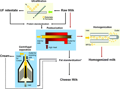 | ||
| Fig. 1 A schematic diagram illustrating a typical milk manufacturing process with the main operational units of ultrafiltration, pasteurization, homogenization and centrifugal separation. Raw milk is the main input and the products examined in this study from the various operational units are UF retentate, cheese milk (the standardized milk used for the large scale manufacture of cheese such as Cheddar), pasteurized and homogenized milk and cream. The dashed arrow indicates that cream is either added or removed from pasteurized milk depending on the required final fat composition of the cheese milk. | ||
In the results and discussion section, we demonstrate a thorough study of experimental data obtained and appropriate analyses that can be performed for a complex soft matter system such as the MFGM using AFM. The results, combined with the structure and composition results from other techniques such as CLSM can give a greater insight into the fundamental nature of MFGs.
2 Materials and methods
2.1 Milk samples
Five different samples: raw milk, raw UF retentate, cheese milk (the standardized milk used for the large scale manufacture of cheese such as Cheddar), commercial pasteurized and homogenized milk and cream, were investigated in this AFM study. All milk samples except the commercial milk were obtained from Murray Goulburn (Cobram, Victoria, Australia). Commercial pasteurized and homogenized milk (hereafter referred to as homogenized milk) was obtained from the local supermarket. The typical composition of these process streams has been reported previously.42.2 Preparation of milk samples for AFM
Other than dilution of the milk samples, no further treatment of the samples was required for AFM studies and samples were used as received. Milk samples were stored in the refrigerator (4 °C) and were used within three days of delivery. All samples were allowed to equilibrate to room temperature (20–25 °C) before use for AFM and were diluted to 5% by adding 1 ml of sample into 20 ml of simulated milk ultrafiltrate (SMUF) solutions.4 A small volume of sample was transferred onto the AFM fluid cell assembly and then fitted to the AFM stage.2.3 Imaging and probing mechanical strength using AFM
AFM experiments were performed using a MFP-3D AFM from Asylum Research (Santa Barbara, USA). AFM was used to image the surfaces of MFGs of various milk samples and to probe their mechanical strength. The cantilevers used were triangular silicon nitride MLCT cantilevers obtained from Veeco (Santa Barbara, USA), with a spring constant of 0.013 ± 0.01 Nm−1 and 0.039 ± 0.04 Nm−1 for the longest and second longest tips, respectively, measured using the thermal method,18 and a manufacturer reported radii curvature of 40 nm. The force applied to the MFGs was kept well below 800 pN, which translated to an indentation into the MFGs of less than 20 nm. This amount of indentation into the MFG was assumed to be less than 10% of the total height of the MFG, a required condition to apply the Hertz model. A slow tip approach velocity of less than 1 μm s−1 was chosen to perform indentations so that the effects of hydrodynamics could be ignored.19–21The AFM fluid cell was fitted with a circular glass disk to serve as the substrate support. The glass disk was carefully cleaned by sequentially soaking in detergent, 10% v/v laboratory grade nitric acid and then 10% w/v sodium hydroxide solutions for at least one hour each with copious rinsing using MilliQ (18.2 mΩ cm−1) water. The glass disk was then soaked in 0.01% v/v poly-L-lysine (PLL) solution (Sigma-Aldrich, NSW, Australia) to enhance the adhesion of milk fat globules. The PLL soaked glass disk was allowed to dry under filter cleaned air, then rinsed with a copious amount of MilliQ water to wash away loosely attached PLL. The AFM fluid cell assembly was cleaned via soaking in detergent and then rinsing with MilliQ water, ethanol and MilliQ water, respectively. The fluid cell was dried under a stream of filtered nitrogen gas and the glass disk was fitted to the cell. Diluted samples were then deposited on to the top of the glass disk. The fluid cell assembly was carefully fitted onto the AFM stage after approximately 15 min to allow for milk fat globules to attach to the glass disk. AFM imaging and indentation experiments were performed at ambient laboratory conditions of 20–25 °C. Once the cantilever was placed in the cantilever tip holder and fitted to the AFM, the tip was lowered to just above the top surface of the glass disk. Visualization of the milk fat globules resting on the glass disk surface was possible via a Nikon Eclipse TE2000-U inverted light microscope attached to the AFM. Once a milk fat globule was chosen visually, the cantilever tip was lowered further, placed in the middle and on top of the globule. Imaging was conducted in alternating current (AC) or intermittent contact mode at slow scanning speeds because of the delicate nature of the milk fat globule membrane and to impose the minimum amount of force possible on its surface.22 Once an image was captured, the AFM scanner mode was switched to contact mode and the ‘Go There’ function in the MFP-3D software was used to take force curves on desired positions within the image.
2.4 Force curve analysis for MFGM elasticity
Individual force distance cycles of the AFM cantileverversus piezo motion were used to determine milk globule membrane elasticity by converting these data to force versus indentation curves. Fig. 2 shows a typical force versus piezo movement curve between an AFM cantilever tip and the MFGM surface for an elastic deformation where there is little hysteresis between the approach and the retract curves of the cantilever tip.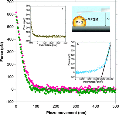 | ||
| Fig. 2 A typical force versus distance or piezo movement curve for the approach and retraction of a sharp cantilever tip on a MFGM. The red dots indicate the approach branch and the green dots indicate the retract branch of the force curve. The lack of hysteresis between the approach and retract curves suggests that the deformation of the MFGM surface is reversible or elastic. Inset ‘a’ shows the force plot converted to a force versus indentation curve. The zero on the x-axis in this plot indicates the contact point. Inset ‘b’ shows the slope of the force versus indentation2 curve used to extract the Young's modulus. The schematic diagram of the AFM setup shows a cantilever tip positioned over the apex of a milk fat globule (MFG) that is immobilised on the surface. | ||
The piezo movement was converted to an indentation value by performing a distance balance between the cantilever and the MFG surface expressed in eqn (1).
| Δl = −ΔD + Δz + Δd | (1) |
Hertz analysis for contact between two elastic axisymmetric objects was used to obtain the Young's elastic modulus of the MFGM of the milk samples.24,25 The most common AFM cantilever tip geometries used for AFM studies of single soft bodies such as cells are pyramidal tips15,26 or a spherical probe attached to the tip.27,28 The Hertz model relation used for elastic modulus extraction in this study employed eqn (2),29 which approximates the tip geometry to a conical indenter.30 Approximating the tip shape to a conical indenter is a commonly used practice since it simplifies the complications of different stress distributions due to edge effects of a pyramidal indenter.
 | (2) |
Where F is the force, E is the Young's modulus, tan α is the hypothetical cone angle, ν is the Poisson's ratio (0.5) and x is the indentation depth. The slopes of the force versus the square of indentation curves were used to obtain the elastic modulus as shown in the inset of Fig. 2.
Hertz theory has been readily used in the analysis of biological systems,14,31 yet some basic assumptions in Hertz theory may not always be satisfied. The material being probed must be isotropic on the scale of the indentation, which is often not the case for cells or other biological surfaces, including the MFGM which is inhomogeneous due to the presence of various components that protrude from the surface such as phospholipids, glycolipids, glycoproteins and enzymes.32 This is often accounted for by sampling a large number of force curves over the surface and spacing them on the scale of tens to hundreds of nanometres apart and reporting average values. The above model also assumes that the material is an infinite half space, compared to the scale of the indenter (AFM tip) and the amount of deformation. This constraint is satisfied by using very low forces to impose very small indentations into the surface. As the MFGM may exhibit some lateral heterogeneity, a large number of force curves (>55) were taken for each sample over a number of MFG to obtain an average elastic modulus that is statistically significant.
2.5 Statistical analysis
Statistical analysis of the data was performed using statistical packages in Minitab (Minitab Inc., State College, Pa., USA). Comparison of means of pools of data was performed by using a one way analysis of variance (ANOVA) and Tukey's paired comparison with a significance level of α = 0.05.3 Results and discussion
3.1 AFM images of various MFGs
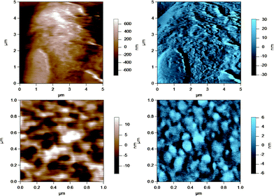
AFM was used to image the fluid-like MFGM of five different samples from various steps during the processing of milk and preparation of milk for cheese making. The MFGM was imaged in situ on the globule in its natural state without the need for isolating the membrane, therefore without potentially changing the structure and the composition of the membrane. Fig. 3 to 7 represent the height (in brown) and amplitude (in blue) images taken using AC mode AFM imaging for the milk fat globules in raw milk, raw UF retentate, commercial pasteurized and homogenized milk (homogenized milk), cream and cheese milk, respectively. For each preparation, a large scan size is shown at the top to display the overall size of the MFG. The MFGs are in the order of microns in radius, thus tip convolution effects are expected at the sides of the MFG. The second image, directly below is a smaller scan size of the same globule where the curvature and tip convolution effects are less significant. The amplitude images of the AFM cantilever are shown alongside the height images to help the reader identify various surface features, since the edges often offer better contrast in the amplitude images. The images reported are selected from a much larger collection of images where the features discussed below reflect typical features for a sample type. First, we discuss the morphological variation of the images, surface roughness results are presented and discussed in a subsequent section.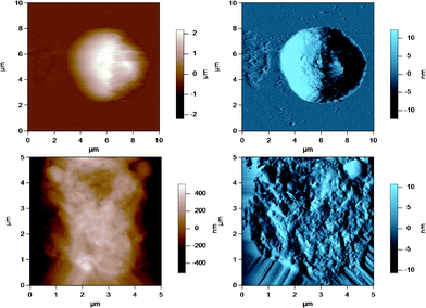 | ||
| Fig. 3 AC mode AFM images for raw milk fat globules in SMUF. The brown image (left) is the height image while the blue image (right) is the amplitude image. The lower images show a region of the MFG in the top image at a smaller scan size or higher resolution. | ||
 | ||
| Fig. 4 AC mode AFM images for raw UF retentate milk fat globules in SMUF. The brown image (left) is the height image while the blue image (right) is the amplitude image. The lower images show a region of the MFG in the top image at a smaller scan size or higher resolution. | ||
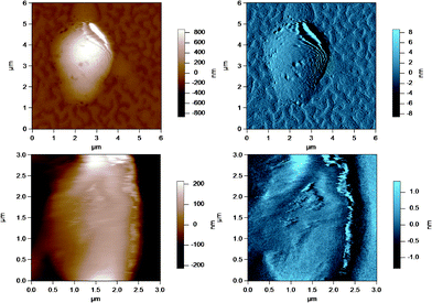 | ||
| Fig. 5 AC mode AFM images for pasteurized and homogenized milk fat globules in SMUF. The brown image (left) is the height image while the blue image (right) is the amplitude image. The lower images show a region of the MFG in the top image at a smaller scan size or higher resolution. | ||
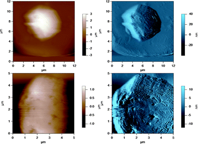 | ||
| Fig. 6 AC mode AFM images for cream milk fat globules in SMUF. The brown image (left) is the height image while the blue image (right) is the amplitude image. The lower images show a region of the MFG in the top image at a smaller scan size or higher resolution. | ||
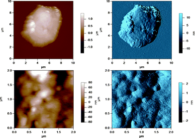 | ||
| Fig. 7 AC mode AFM images for cheese milk fat globules in SMUF. The brown image (left) is the height image while the blue image (right) is the amplitude image. The lower images show a region of the MFG in the top image at a smaller scan size or higher resolution. | ||
These figures show that the MFGs can be successfully imaged within SMUF buffer solution with high resolution using AFM, despite the fluid-like soft nature of the MFGM. The AFM image for each preparation is distinctly different. Raw milk MFGM appears rough with both large and small globular domains. UF retentate also appears very rough at the large scan size and this particular image shows a large elevated region. The image at a higher magnification at a smaller scan size is similar to a porous structure with pores of uniform size and globular domains of similar sizes. In contrast, the homogenized MFG surface looks flat and the scan at a higher magnification shows that the surface is smooth compared to the other MFG surfaces. There are no globular domains of varying sizes as was seen in the raw milk MFGM. The MFGM on the MFG within cream looks similar to the homogenized milk sample in that it also has a flat smooth appearance unlike raw milk. However, the scan at a higher magnification shows that the MFGM within cream has more lateral heterogeneity than the homogenized MFGM. Finally, the cheese milk MFGM has a very globular appearance, with some areas showing aggregates of globules. These globules are all similar in size, unlike raw milk MFGM where the globules are of varying size.
AFM images of the MFGM for these samples show that the MFGM has undergone a drastic change from the native state, which is the raw MFGM to that of the highly processed homogenized MFGM. The loss of the rough globular appearance in the homogenized MFGM and the gain of a flat smooth surface indicates that the high shear rates MFGs undergo during homogenization leads to the loss of MFGM material. Similarly, the widely different appearances of the MFGM observed for the MFG in UF retentate, cream and cheese milk compared to the appearance of the native state indicates that the other processes in milk manufacture, such as ultrafiltration, pasteurization and centrifugal separation change the native MFGM in different ways.
The native MFGM has been found to have a heterogeneous distribution of glycolipids and glycoproteinsviaCLSM studies.4–6,33,34 It is also believed that the MFGM surface is scattered with liquid-ordered and liquid-disordered phospholipid regions,6 which could add to the heterogeneous nature of the MFGM. It can be said that the AFM images reflect such a heterogeneous surface for the native MFGM and that these findings are in agreement with results from other authors.
The ultrafiltration process is used in the milk industry to separate milk serum proteins to standardize the amount of protein in consumer milk and fermented milk products such as cheese and yogurt. The addition of UF retentate to cheese milk improves the coagulation process due to the higher protein content.35 Pressure applied in the ultrafiltration process can reach up to 10 bar36 and the shear forces involved during this process could cause the deposition or adsorption of milk proteins onto the MFGs remaining in the concentrated retentate liquor, where the proteins form a gel-like structure. The darker regions in Fig. 4 of the MFGM in the UF retentate are most likely pores from protein in a gel like structure. The porous appearance could reflect the roughness of the MFGM below the protein coating or it could simply be due to the method in which protein adsorption occurs at high pressure. CLSM images of the MFGM within UF retentate prepared under the same conditions showed a large amount of adsorbed milk protein attachment to MFGs that was much thicker than the actual MFGM in places.4 Although homogenized milk was shown to have the highest amount of adsorbed protein, UF retentate MFGs still have a high amount of adsorbed protein compared to the average droplet.4 Furthermore, most of the AFM images for UF retentate MFGs showed a large raised structure on the surface, as shown in the larger scan size of the image in Fig. 4. These areas could be regions where material was deposited on the MFGM surface during high pressure filtration and they reinforce the uneven nature of these surfaces.
The surface of cheese milk has a globular appearance similar to raw milk. This is consistent with the fact that the major process step in the production of cheese milk is pasteurization with the final cheese milk obtained by mixing a fraction of UF retentate with pasteurized milk.37 Pasteurization is a process used in the dairy industry where the milk is heated to high temperatures for short time intervals in order to reduce microbial growth and improve shelf-life. It is generally accepted that this process does not cause significant measurable damage to the MFGM.37 A comparison of the AFM images of raw and cheese milk MFGM supports this idea. However, it has been reported that heating milk serum proteins causes them to associate with the MFGM.38 For instance, β-lactoglobulin, a major whey protein was found to covalently bind to the MFGM at temperatures greater than 65 °C.38,39 The AFM images for cheese MFGM do indeed show a slightly more ordered globular appearance than the raw milk MFGM. Perhaps this appearance is due to small amounts of aggregated serum proteins associating with the MFGM during pasteurization. At this stage, it is not clear whether the globular appearance of cheese MFGM is indeed due to whey protein association. Further studies on the protein composition (which includes whey proteins), of the MFGM needs to be conducted to clarify this matter.
Cream is obtained via centrifugally separating a mixture of pasteurized UF retentate and raw milk. This process applies a centrifugal force to the sample to separate proteins from fat globules. The shear rates attained in this unit operation should not be sufficient to smooth the surface of the membrane as would occur for a homogenizer. Nevertheless, compared to raw milk, the cream sample looks more smooth, albeit with more lateral heterogeneity than homogenized milk. This result could be the effect of the forces in the centrifugal separator or due to the coalescence of milk fat globules in the creaming process. Coalescence will result in larger globules with a larger surface area to be covered by the same amount of membrane material which may induce changes in the MFGM.
Previous authors have successfully probed the composition of the MFGM using confocal laser scanning microscopy and specific dyes.4,5 In such studies, the state of the native membrane and the amount of extraneous proteins adsorbed on the surface before and after processing of samples were investigated by visual comparison using the dyes wheat germ agglutinin (WGA 488), which specifically binds to components in the MFGM and FCF fast green, which binds to proteins adsorbed to MFG surface. Generally, the native MFGM was found intact and thickest on raw milk, while UF retentate and cheese milk samples contained some MFGM, but this was not as thick. In contrast the MFGM was largely absent from the MFGs of the homogenized milk sample. SDS-PAGE analysis confirmed the presence of the native membrane on fat globules in all milk samples apart from homogenized milk which largely contained casein.4
Visually scanning the AFM images shows that the raw milk membrane appears to be very rough and globular, whereas the homogenized milk globule surface appears very smooth without any globular appearance. It is possible that the shear rates encountered by the fat globule surface during homogenization renders the left over coating smooth due to the removal, deposition or association of material from the globule surface. The 1.5 μm scan of homogenized milk (in Fig. 5) also appears to have aggregated material on the surface and these could be aggregated casein and whey proteins.
One of the main advantages of AFM is that it can be used to image the surface of biological samples in their native environment. Therefore, artifacts due to sample modification can be minimized, especially when compared to transmission electron microscopy (TEM) and scanning electron microscopy (SEM) where sample preparation often involves chemical fixation and dehydration. Thus, the differences in the morphological characteristics of the MFGM surfaces reflect differences from the milk processing steps, not sample preparation. AFM imaging also allows an appreciation of the size differences of MFGs in the various preparations. The sizes of the MFGs imaged in this study were consistent with observations by other techniques such as dynamic light scattering (DLS).4
3.2 AFM Imaging of smaller globular structures and MFGM damage
Fig. 8 shows an AC mode AFM image of small globular structures adsorbed to the substrate (glass disk) surface. The large object to the top left corner is part of a homogenized MFG. These small globular structures could be either casein micelles or fragments of MFGs created during the homogenization process.40Fig. 9 shows AFM images of casein micelle like structures with height versus distance graphs directly below which show the cross section at positions indicated by the lines across the AFM images. The top image is identical to that in Fig. 8, where the casein micelle like structure (inside the blue circle) is much smaller (in both diameter and height) in comparison to the MFG in the top left hand corner. The bottom images are the height (in brown) and amplitude (in blue) images of another AFM scan of such casein micelle like structures. The cross sections of two micelles (inside the blue circles) are shown in red and green in the height versus distance graphs directly below. These graphs indicate that the height of the micelles range from 100 to 400 nm. This result is in good agreement with the height of micelles obtained by Uricanu and coworkers from their AFM imaging study, where they reported the casein micelle height to be in the range of 100 to 400 nm with an average height of 214 nm.11 More importantly, this image shows that there is a vast size difference between the MFGs and the casein micelles or fragments, which allows easy contrast between the two for the purpose of optically choosing MFGs to image viaAFM.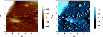 | ||
| Fig. 8 AC mode AFM image of casein micelles in a homogenized milk sample adsorbed to the glass disk. The top left hand corner of the image shows a homogenized MFG, which is much larger in size compared to the casein micelles. The brown image (left) is the height image while the blue image (right) is the amplitude image. | ||
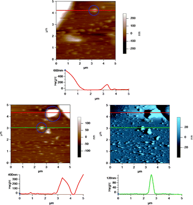 | ||
| Fig. 9 AC mode AFM images of casein micelles in a homogenized milk sample adsorbed to the glass disk. The height versus distance graphs below the images show the cross section of the images at the position indicated by the horizontal lines across the images. Selected casein micelles or MFG fragments are highlighted inside the blue circles in the images. The top height AFM image is identical to that in Fig. 8. The bottom images are the height (in brown) and amplitude (in blue) of a different AFM scan of casein micelle like structures. The red and the green lines correspond to the red and green height profiles, respectively, shown directly below the images. | ||
In some cases, AFM imaging showed a damaged or ripped membrane, as shown in Fig. 10, where there is a clearly defined region of damage in the MFGM surrounding the MFG. This region may have been damaged during milk collection, transport and storage, where physical damage to the MFGs can occur due to air incorporation and temperature fluctuations that allow fat to melt and crystallize.32 It is possible that the cantilever tip could have caused damage while raster scanning over the MFGM surface, although AC mode imaging limits lateral force interactions between the tip and sample. This significantly reduces the potential to damage a soft surface. More importantly, AFM imaging can identify MFGs that appear to have significant damage to the MFGM.
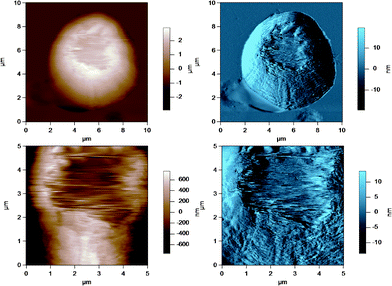 | ||
| Fig. 10 AC mode AFM amplitude image of a raw milk fat globule showing a damaged MFGM at the apex of the globule. The lower images show a region of the MFG in the top image at a smaller scan size or higher resolution. | ||
3.3 MFGM RMS Roughness
A surface roughness analysis was performed on the AFM height images to find any variations in the different milk samples that could reflect the different milk processing steps. The graph in Fig. 11 shows the root mean square (RMS) roughness of the MFGM of various milk samples on a 500 × 500 nm2 scale. In ascending order of roughness, UF retentate MFGM appeared the smoothest, followed by cheese milk, raw milk and homogenized MFGM. The cream MFG had the roughest MFGM. The statistical comparison indicated by the letters above the bars in Fig. 11 shows that the roughness of homogenized and cream MFGMs are distinctly different to the rest of the samples tested.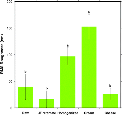 | ||
| Fig. 11 The mean RMS roughness of the surface of MFGM for five different milk samples obtained from AC mode AFM imaging in liquid for 500 × 500 nm scan sizes. Data presented as mean ± SD of the mean, indicated by the error bars. Means that do not share the same letter indicated above the bar are statistically different (p < 0.05). n= 9, 4, 6, 4 and 6 respectively, for milk samples from left to right displayed in the figure. | ||
The morphological variations in the AFM images lead to expected variations in surface roughness. The 500 nm scan size was the largest scan size for which the roughness could be compared before the comparisons became statistically equivalent for the different sample types. Caution should be used for scan sizes larger than 500 nm as error in the RMS roughness is increased due to systematic errors from curvature of the MFGs which distort the surface roughness analysis.
Furthermore, the roughness of the most processed milk samples (homogenized milk and cream) were found to be larger than raw milk, UF retentate and cheese milk samples. This is despite these samples appearing smooth in the AFM images. This difference may be due to the height scales of the images which were set to maximize the contrast, resulting in images appearing smoother, whereas roughness is based on the absolute height scale. It is important to note that the RMS roughness, although the most commonly used roughness analysis, gives the roughness for only one moment of the distribution for a surface which has a distribution of heights. This description is not sufficient to account for the lateral heterogeneity of a sample. One could examine several distributions to convey what may be subtle changes in the height distributions of the samples, yet the actual images are sufficient to show these differences. Nevertheless, gross differences in roughness, reflected by statistical comparisons show that the surface of the most processed samples, homogenized and cream, are different to the milk samples from earlier in the processing and preparation of milk, indicating that the damage or change in the MFGM is greater during homogenization and coalescence (or creaming) in centrifugal separation than during ultrafiltration and pasteurization.
3.4 Young's modulus
CLSM and SDS-PAGE analysis techniques offer a diagnostic way to visually examine the differences between some of the surface constituents of the MFGM. With AFM, one can obtain a quantitative result of the physical nature of the MFGM. The heterogeneous nature of the MFGM renders it difficult to ascertain exactly what is chemically being probed by the AFM at the interface. However, a more wholesome understanding of the chemical and physical nature of the MFGM can be obtained by combining the quantitative AFM results with the chemical composition of the MFGM obtained viaCLSM.Therefore, AFM was also used to probe the elasticity of the different types of milk fat globule membranes. The stiffness of the MFGM can change due to alterations in the chemical and physical properties of the MFGM onset by various factors such as high pressure, high shear rates and high heat during various steps of the milk manufacturing process. As a measure of elasticity we report the average Young's modulus for the five different types of milk, shown in Fig. 12. The Young's modulus of the MFGM of the five different milk samples were all in the tens to hundreds of kPa range. UF retentate displayed the most elastic MFGM, followed by raw milk and cheese milk with very similar elastic moduli. Cream and homogenized milk had the stiffest MFGMs. The results consolidate the trend seen through AFM imaging and roughness analysis, that the MFGM surface of the most processed milk samples, homogenized and cream, are very different to the native MFGM and that they are the most changed samples when compared to UF retentate and cheese milk.
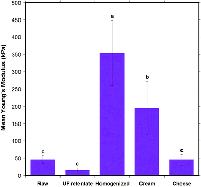 | ||
| Fig. 12 The mean Young's modulus of the MFGM of five different milk samples obtained from AFM indentation experiments. Data presented as mean ± SD of the mean, indicated by the error bars. Means that do not share the same letter indicated above the bar are statistically different (p < 0.05). n= 173, 128, 56, 60 and 143 respectively, for milk samples from left to right displayed in the figure. | ||
A statistical comparison of the Young's moduli for the five milk samples, as shown by the letters above bars in Fig. 12, indicates that the stiffness of raw, UF retentate and cheese milk MFGM are no different to each other, but they are collectively different from homogenized milk and cream. This indicates that the ultrafiltration and pasteurization process does not effect components in the membrane that contribute to stiffness. This is in agreement with the general belief that ultrafiltration and pasteurization causes minimal damage to the MFGM. Cream was found to have a Young's modulus of 195 ± 76 kPa, which is a significant difference compared to raw, UF retentate and cheese milk considering that the only extra process step it encounters is centrifugal separation to induce creaming. Although the centrifugation process is only used for phase separation and milk is not expected to undergo shear, the centrifugal force and the coalescence of the MFGs might alter the MFGM enough to change the stiffness.
It must be noted that the elastic modulus of all the milk samples agree with what is plausible for the stiffness of a biological membrane under near physiological conditions. The typical Young's modulus of unfixed cells is in the range of 1 to 10 kPa and 100 kPa for fixed cells. In comparison, the Young's modulus for rubber is 2 MPa and that of glass is 1 GPa.41 The stiffness of the MFGMs fall between unfixed and fixed cells, in the range for a biological membrane. Homogenized milk is the stiffest sample since it displays the highest Young's modulus, 354 ± 94 kPa. This suggests that the very high shear rates the fat globules are exposed to in the homogenization step drastically alters the MFGM so that the stiffness of the membrane increases significantly. The higher stiffness of homogenized milk also seems consistent with the fact that this preparation is reported to have the highest mass of casein micelles and whey proteins attached to the MFG surface. The Young's modulus value of homogenized MFGM obtained in this AFM study is comparable to that found by Uricanu and co-workers for casein micelles, in the order of 100 kPa.11 The proteins adsorbed due to the homogenization process where the native MFGM is somewhat destroyed, could increase the stiffness of the membrane. In contrast, UF retentate is revealed to be the softest sample, with a Young's modulus of 16 ± 6 kPa. AFM imaging confirmed the presence of a porous structure, most likely a protein gel on the UF retentate MFGM. The low elastic modulus of UF retentate MFGM can be attributed to the soft nature of the porous coating on the MFGM. It is interesting to note that the variation in the protein composition and structure, such as casein micelles on homogenized MFGM and gel-like protein in the UF retentate MFGM, can result in large differences in the stiffness of the membrane.
This AFM elasticity study gives an insight into the two different processing steps when analyzed in conjunction with results from other techniques such as CLSM. It shows that ultrafiltration can superficially alter the MFGM and homogenization irreversibly damages the MFGM. Although the difference in the membranes of the native MFGM (raw milk) and the ultimate processed milk sample (homogenized milk) cannot be pinpointed to particular membrane constituents, it is evident that there is a large difference between the surfaces.
3.5 Thickness of the MFGM
AFM also allows further opportunities to quantify features of the MFG such as its thickness when the MFG is under near physiological conditions without any chemical fixing. The force versus distance curves obtained from AFM sometimes show a step in the region after the cantilever has contacted the surface, as shown in Fig. 13. Such a step can be interpreted as the tip poking into the MFGM membrane and then continuing to indent the next surface. Although these events did not often occur during AFM indentation measurements, occasionally the tip penetrated the membrane for all milk samples. Such force curves were analyzed to obtain an average apparent membrane thickness for all milk samples. The extraction of the thickness was performed by converting the deflection versus piezo motion curves to force versus indentation curves as explained in Section 2.4. The horizontal distance between the step, (see Fig. 13), was used as the apparent membrane thickness.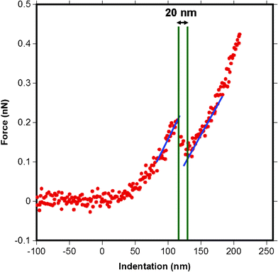 | ||
| Fig. 13 A force versus indentation curve for a pyramidal tip indenting raw milk MFGM showing a step, or a stab into the membrane. The thickness of 20 nm is extracted by measuring the distance between intersections of the blue and green lines at the beginning and the end of the step. The blue lines represent the slope on the indentation into the sample before and after poking and the green lines are where the x-axis intersects the blue lines. Zero on the x-axis indicates the contact point. | ||
The membrane thickness results are summarized in Fig. 14 which shows that the homogenized and cheese milk had the thinnest membranes while cream and raw milk had thicker membranes than the previous samples. UF retentate had the thickest MFGM. A statistical comparison (p < 0.05) shows that the samples fall into two different groups, where the membrane thickness of raw milk and UF retentate with a larger thickness is significantly different to that of cheese and homogenized milk with smaller thicknesses. The order of magnitude for the membrane thickness obtained from this AFM is in good agreement with values found in literature, of 10–50 nm for the MFGM.6 Various reconstituted supported phospholipid bilayers are reported to be between 3–6 nm in height determined viaAFM topography analysis of surface scanned images.42–45 This indicates that the MFGM consists of more than just a lipid bilayer, indeed the MFGM is generally accepted as a trilayer structure that includes a combination of an outermost lipid bilayer and an innermost single lipid layer with a small amount of cytoplasm material encapsulated in between the single layer and the bilayer, in addition to various associated membrane proteins.2,6
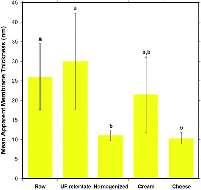 | ||
| Fig. 14 The mean apparent thickness of the MFGM for five different milk samples obtained from AFM force versus indentation data curves. Data presented as mean ± SD of the mean, indicated by the error bars. Means that do not share the same letter indicated above the bar are statistically different (p < 0.05). n= 14, 6, 23, 7 and 7 respectively, for milk samples from left to right displayed in the figure. | ||
Fig. 15 plots the mean Young's modulus as a function of the apparent MFGM thickness. This figure indicates that there is no clear relationship between MFGM elasticity and thickness, indicating that the indentation is a representation of the elasticity of the MFGM with minimal effects from MFG size and core. This is also a strong indication that MFGM elasticity is based on compositional differences in the MFGM that is consistent with biochemical and CLSM data.4
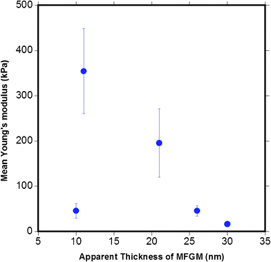 | ||
| Fig. 15 The relationship between the mean Young's modulus calculated versus the apparent MFGM thickness. The graph indicates that the elasticity of the MFGM is not a function of the thickness of MFG. | ||
From these results, it can be concluded that the MFGM thickness decreases for milk products further down the manufacturing process. This reinforces the theory, supported by the dairy community, that the MFGM is damaged from milk processing steps such as homogenization. The raw milk MFGM which is in its native state has one of the thickest membranes, consistent with the fact that it has the original intact membrane with little damage from the milk processing steps. The UF retentate MFGM has porous coating adsorbed to it during ultrafiltration. The thickness of the UF retentate MFGM could reflect this process. Homogenized milk MFGM thickness reflects loss of MFGM material during homogenization, although compositional changes obtained from CLSM studies have shown that homogenized milk had the highest amount of adsorbed protein.4 The reason for the similarity in the thickness of the cheese milk MFGM to that of the homogenized milk is unclear, as cheese milk does not go through homogenization, although cream is mixed in to this milk for fat standardization. Cream is the only sample that is not statistically different to the other samples. There is no obvious explanation for this result, although it can be said that the centrifugal separation and the coalescence occurring in the creaming process could change the composition of the membrane. Although the MFGM thicknesses agree with the range reported in literature, results from the MFGM thickness analysis should be treated with caution and used as an upper band of the MFGM thickness, because there may be deformation of the MFG that also contributes to the MFGM thickness. The comparison of the mean Young's modulus to the apparent MFGM thickness indicates that it is the composition, particularly whether a protein coating versuslipid membrane that cause the changes in not only the elastic modulus, but also the roughness and the thickness of the MFGM.
More sophisticated models for calculating the elasticity were also examined by extracting the Young's modulus using a shell model that required the thickness.46,47 In a shell model, the Young's modulus is a function of the inverse square of the thickness of the shell. The error in the MFGM thickness measurements severely limited any statistically significant comparisons between the MFGM indentation data.
4 Conclusions
The milk fat globule membrane is a complex system composed of diverse membrane constituents that change with various processing steps during manufacture of homogenized and pasteurized milk for consumption. Experiments such as solvent extraction and chromatography can be performed to analyse the chemical composition of the milk fat globule membrane. However, these techniques are bulk analysis methods and do not shed light on the exact composition of the interface, which is what was under examination in the AFM technique studied here. Techniques such as CLSM can show various constituents of the surface of the MFG. The disadvantage of such a technique is that there is little scope for obtaining quantitative compositional information and only known MFGM constituents can be identified via the use of an appropriate dye and/or antibody. The heterogeneous nature of the MFGM renders is difficult to completely characterize the chemical and physical changes that occur to the MFGM during processing using any one technique. By correlating the quantitative results that can be obtained from AFM studies, as shown here, with the results of CLSM studies and other bulk analysis methods, one can obtain the greatest insight in to such a complex soft matter system as the MFGM.In the context of food science and engineering, AFM is a useful technique in determining the effects of various milk processing steps on the MFGM. AFM can be used to detect changes in the MFGM through each processing step in the manufacture of milk and preparation of dairy products. It is a useful tool for obtaining high resolution images of the MFGM in near physiological conditions. AFM allows the comparison of milk samples which have undergone different milk processing steps through images and properties of the MFGM such as stiffness, roughness and membrane thickness. This particular study showed that the MFGM changed drastically from the native state to the homogenized state. UF retentate MFGM showed a protein gel-like structure on the surface very different to other milk samples, while the cheese milk MFGM appeared slightly more globular than the native raw MFGM possibly due to the association of protein.
A suggestion for future research that can enhance AFM as a useful technique for dairy science and other complex soft matter systems is to combine a technique such as CLSM with AFM measurements. Combined CLSM and AFM techniques are increasingly used in biological cell mechanics studies.48–50 Such a study will allow the surface of the MFGM to be visualized and probed in specific areas allowed by the application of dye that binds to specific constituents of the MFGM. AFM also allows the quantification of various aspects of soft matter systems such as investigating the temperature effect on membranes and looking at the links between the various lipids and protein composition of the membrane.
Acknowledgements
Murray Goulburn is thanked for supplying the raw milk, UF retentate, cream and cheese milk samples. The Australian Research Council and Dairy Innovation Australia Ltd. are thanked for financial support. The Particulate Fluids Processing Centre, a special research centre of the Australian Research Council is thanked for providing infrastructure support for this project.References
- S. Gallier, D. Gragson, C. Cabral, R. Jimenez-Flores and D. W. Everett, J. Agric. Food Chem., 2010, 58, 10503–10511 CrossRef CAS.
- J. M. Evers, Int. Dairy J., 2004, 14, 747–760 CrossRef CAS.
- C. Lopez, Curr. Opin. Colloid Interface Sci., 2011, 16, 391–404 CrossRef CAS.
- L. Ong, R. R. Dagastine, S. E. Kentish and S. L. Gras, J. Food Sci., 2010, 75, E135–E145 CrossRef CAS.
- S. Gallier, D. Gragson, R. Jimenez-Flores and D. Everett, J. Agric. Food Chem., 2010, 58, 4250–4257 CrossRef CAS.
- C. Lopez, V. Briard-Bion, O. Ménard, E. Beaucher, F. Rousseau, J. Fauquant, N. Leconte and B. Robert, Food Chem., 2011, 125, 355–368 CrossRef CAS.
- B. Jena and J. Horber Heinrich, Atomic Force Microscopy in Cell Biology, Academic Press, California, 2002, vol. 68, 1–31 Search PubMed.
- P. Smith and A. Dahlman, J. Am. Oil Chem. Soc., 2005, 82, 165–168 CrossRef CAS.
- A. Handojo, Y. Zhai, G. Frankel and M. A. Pascall, J. Food Eng., 2009, 92, 305–311 CrossRef CAS.
- S. Gallier, D. Gragson, R. Jimenez-Flores and D. W. Everett, J. Agric. Food Chem., 2010, 58, 12275–12285 CrossRef CAS.
- V. I. Uricanu, M. H. G. Duits and J. Mellema, Langmuir, 2004, 20, 5079–5090 CrossRef CAS.
- W. A. Ducker, T. J. Senden and R. M. Pashley, Nature, 1991, 353, 239–241 CrossRef CAS.
- C. Rotsch and M. Radmacher, Biophys. J., 2000, 78, 520–535 CrossRef CAS.
- J. H. Hoh and C. A. Schoenenberger, J. Cell Sci., 1994, 107, 1105–1114 Search PubMed.
- S. Cross, Y. Jin, J. Rao and J. K. Gimzewski, Nat. Nanotechnol., 2007, 2, 780–783 CrossRef CAS.
- J. A. Lucey and H. Singh, Food Res. Int., 1998, 30, 529–542 CrossRef.
- G. I. Titapiccolo, M. Alexander and M. Corredig, Dairy Sci. Technol., 2010, 90, 623–639 CrossRef CAS.
- J. L. Hutter and J. Bechhoefer, Rev. Sci. Instrum., 1993, 64, 1868–1873 CrossRef CAS.
- I. U. Vakarelski, R. Manica, X. Tang, S. J. O'Shea, G. W. Stevens, F. Grieser, R. R. Dagastine and D. Y. C. Chan, Proc. Natl. Acad. Sci. U. S. A., 2010, 107, 11177–11182 CrossRef CAS.
- R. R. Dagastine, R. Manica, S. L. Carnie, D. Y. C. Chan, G. W. Stevens and F. Grieser, Science, 2006, 313, 210–213 CrossRef CAS.
- G. B. Webber, S. A. Edwards, G. W. Stevens, F. Grieser, R. R. Dagastine and D. Y. C. Chan, Soft Matter, 2008, 4, 1270–1278 RSC.
- M. Radmacher, M. Fritz and P. K. Hansma, Biophys. J., 1995, 69, 264–270 CrossRef CAS.
- W. R. Bowen, R. W. Lovitt and C. J. Wright, Biotechnol. Lett., 2000, 22, 893–903 CrossRef CAS.
- H. Hertz, Miscellaneous Papers, Macmillan and Co. Ltd., New York, 1896 Search PubMed.
- E. K. Dimitriadis, F. Horkay, J. Maresca, B. Kachar and R. S. Chadwick, Biophys. J., 2002, 82, 2798–2810 CrossRef CAS.
- M. Lekka, P. Laidler, D. Gil, J. Lekki, Z. Stachura and A. Hrynkiewicz, Eur. Biophys. J., 1999, 28, 312–316 CrossRef CAS.
- R. Mahaffy, C. Shih, F. MacKintosh and J. Kas, Phys. Rev. Lett., 2000, 85, 1777–1793 CrossRef.
- V. Lulevich, T. Zink, H. Chen, F. Liu and G. Liu, Langmuir, 2006, 22, 8151–8155 CrossRef CAS.
- M. J. Rosenbluth, W. A. Lam and D. A. Fletcher, Biophys. J., 2006, 90, 2994–3003 CrossRef CAS.
- G. G. Bilodeau, J. Appl. Mech., 1992, 59, 519–523 CrossRef.
- M. Radmacher, Methods Cell Biol., 2007, 83, 347–372 CrossRef CAS.
- P. Walstra, T. J. Geurts, A. Noomen, A. Jellema and M. A. J. S. van Boekel, Dairy Technology—Principles of Milk Properties and Processes, Marcel Dekker, Inc., New York, 1999 Search PubMed.
- J. M. Evers, R. G. Haverkamp, S. E. Holroyd, G. B. Jameson, D. D. S. Mackenzie and O. J. McCarthy, Int. Dairy J., 2008, 18, 1081–1089 CrossRef CAS.
- S. Gallier, K. C. Gordon, R. Jimnez-Flores and D. W. Everett, Int. Dairy J., 2011, 21, 402–412 CrossRef CAS.
- T. P. Guinee, P. D. Pudja and E. O. Mulholland, J. Dairy Res., 1994, 61, 117–131 CrossRef CAS.
- Dairy Processing Handbook, ed. G. Bylund, Tetra Pak Processing Systems AB, Lund, Sweden, 1995 Search PubMed.
- L. Ong, R. Dagastine, S. Kentish and S. Gras, Austr. J. Dairy Technol., 2010, 65, 222 Search PubMed.
- M. Corredig and D. G. Dalgleish, J. Agric. Food Chem., 1998, 46, 2533–2540 CrossRef CAS.
- D. G. Dalgleish and J. M. Banks, Milchwissenshaft-Milk Science International, 1991, 46, 75–78 CAS.
- M. Michalski, F. Michel and C. Geneste, Lait, 2002, 82, 193–208 CAS.
- T. Ludwig, R. Kirmse, K. Poole and U. Schwarz, Pflug. Arch. Eur. J. Phy., 2007, 456, 29–49 CrossRef.
- W. Ngwa, K. Chen, A. Sahgal, E. V. Stepanov and W. Luo, Thin Solid Films, 2008, 516, 5039–5045 CrossRef CAS.
- S. Kunneke, D. Kruger and A. Janshoff, Biophys. J., 2004, 86, 1545–1553 CrossRef.
- J. Schneider, Y. F. Dufrene, W. R. Barger Jr and G. U. Lee, Biophys. J., 2000, 79, 1107–1118 CrossRef CAS.
- H. A. Kolb, O. Enders and R. Schauer, Appl. Phys. A: Mater. Sci. Process., 1999, 68, 247 CrossRef CAS.
- L. Zhang, M. D'Acunzi, M. Kappl, G. K. Auernhammer, D. Vollmer, C. M. van Kats and A. van Blaaderen, Langmuir, 2009, 25, 2711–2717 CrossRef CAS.
- F. Y. M. Wan, R. D. Gregory and T. I. Milac, SIAM J. Appl. Math., 1998, 59, 1080–1097 CrossRef.
- M. Sato, K. Nagayama, N. Kataoka, M. Sasaki and K. Hane, J. Biomech., 2000, 33, 127–135 CrossRef CAS.
- A. E. Pelling, F. S. Veraitch, C. P. K. Chu, C. Mason and M. A. Horton, Cell Motil. Cytoskeleton, 2009, 66, 409–422 CrossRef CAS.
- R. F. Tabor, H. Lockie, D. Mair, R. Manica, D. Y. C. Chan, F. Grieser and R. R. Dagastine, J. Phys. Chem. Lett., 2011, 2, 961–965 CrossRef CAS.
| This journal is © The Royal Society of Chemistry 2012 |