Metal-free, nitrogen-doped graphene used as a novel catalyst for dye-sensitized solar cell counter electrodes†
Ming-Yu
Yen
a,
Chien-Kuo
Hsieh
b,
Chih-Chun
Teng
a,
Min-Chien
Hsiao
a,
Po-I
Liu
a,
Chen-Chi M.
Ma
*a,
Ming-Chi
Tsai
b,
Chuen-Horng
Tsai
b,
Yan-Ru
Lin
c and
Tsung-Yu
Chou
d
aDepartment of Chemical Engineering, National Tsing Hua University, Hsinchu, 30013, Taiwan, R.O.C.. E-mail: ccma@che.nthu.edu.tw; Fax: +886-35715408; Tel: +886-35713058
bDepartment of Engineering and System Science, National Tsing Hua University, Hsinchu, 30013, Taiwan, R.O.C.
cDepartment of Materials Engineering, Ming-Chi University of Technology, Taipei, 24301, Taiwan, R.O.C.
dDepartment of Mold and Die Engineering, National Kaohsiung University of Applied Sciences, Kaohsiung, 807, Taiwan, R.O.C.
First published on 27th February 2012
Abstract
Nitrogen-doped graphene (NGR) was incorporated as a catalyst and used as a counter electrode in dye-sensitized solar cells (DSSCs). The NGR electrodes showed a number of advantages over other electrodes that consisted solely of graphene or Pt films, including high charge transfer rates, low resistance to diffusion, and low internal resistance.
Since the first demonstration of dye sensitized solar cells (DSSCs) by Grätzel's team,1 these photovoltaic systems have shown great potential for the development of solar cells because of their low cost of fabrication and relatively high energy conversion efficiency. The working principle of DSSCs involves three steps: 1) the photo-induced oxidation of a dye molecule on a working TiO2 electrode; 2) the reduction of the oxidized dye molecule by I−; and 3) the diffusion of the oxidized species from the surface of the dye to the counter electrode, and its involvement in the regeneration of I−, with the assistance of a catalyst. Platinum (Pt) is typically used as the catalyst in DSSCs; it induces an intense level of electrocatalytic activity in the iodide/triiodide pair. Although Pt has the advantage of high electroactivity and being highly chemically stable, it is expensive. Therefore, a feasible alternative is required.
A number of authors have shown that carbonaceous materials such as carbon black,2 carbon nanotubes (CNTs),3,4 graphite,5 and graphene (GR)6–10 show promise as alternative catalysts. Among these candidates, GR (a two-dimensional carbonaceous material) is highly attractive even when compared with Pt, because of its high electrical conductivity and high specific surface area. Several authors have shown the correlation between the structure of GR and its electrochemical properties, especially for its charge transfer resistance.6,10 Roy-Mayhew reported that GR sheets have the catalytic and electrical properties required for a counter electrode material, as well as the flexibility.6 They showed that the performance of DSSCs could be controlled through the C![[thin space (1/6-em)]](https://www.rsc.org/images/entities/char_2009.gif) :O ratio of GR, following reduction by a thermal process. Kavan demonstrated that the electrocatalytic properties of GR nanoplatelets that take part in the redox reaction are related to the incidence of defects and the concentration of oxygen-containing groups.7 Choi et al. presented a GR counter electrode prepared by electrophoretic deposition (EPD). They showed that GR is a candidate for replacing Pt metal.8 Because of the tendency of aggregation, Zhu demonstrated that the porosity of the GR electrode was improved through the incorporation of CNTs, which enhanced the diffusion rate.9 According to the literature, defect-rich GR has unique properties that enable its use as a counter electrode due to its high incidence of active sites and its hydrophilic oxygen-containing groups. In our previous study,11 we demonstrated an approach to improve the electrical conductivity and electrochemical properties of GR; this involved incorporating Pt nanoparticles into GR to strike a suitable balance between the connection of isolated aromatic domains and the concentration of defects on the surface of GR. However, the high cost and risk of corrosion of Pt through the redox species in the electrolyte hindered the development of the proposed DSSCs. This outcome highlights the demand for low-cost, easily fabricated, and corrosion-resistant materials for counter electrodes.4,12
:O ratio of GR, following reduction by a thermal process. Kavan demonstrated that the electrocatalytic properties of GR nanoplatelets that take part in the redox reaction are related to the incidence of defects and the concentration of oxygen-containing groups.7 Choi et al. presented a GR counter electrode prepared by electrophoretic deposition (EPD). They showed that GR is a candidate for replacing Pt metal.8 Because of the tendency of aggregation, Zhu demonstrated that the porosity of the GR electrode was improved through the incorporation of CNTs, which enhanced the diffusion rate.9 According to the literature, defect-rich GR has unique properties that enable its use as a counter electrode due to its high incidence of active sites and its hydrophilic oxygen-containing groups. In our previous study,11 we demonstrated an approach to improve the electrical conductivity and electrochemical properties of GR; this involved incorporating Pt nanoparticles into GR to strike a suitable balance between the connection of isolated aromatic domains and the concentration of defects on the surface of GR. However, the high cost and risk of corrosion of Pt through the redox species in the electrolyte hindered the development of the proposed DSSCs. This outcome highlights the demand for low-cost, easily fabricated, and corrosion-resistant materials for counter electrodes.4,12
This study details the use of a nitrogen-doped graphene (NGR) catalyst prepared using the hydrothermal method,13 used in DSSC counter electrodes (Fig. 1(a)). Compared with previous studies, NGR has several advantages over the material used in our previous study, namely 1) a high surface area because of its specific two-dimensional structure, which resulted in a highly efficient current density exchange at the interface between GR and the electrolyte; 2) more extensive aromatic domains than GR, leading to an improved electrical conductivity; and 3) the nitrogen-doped domains on the surface of GR have selectivity for redox species in the reduction reaction (I3− + 2e− → 3I−), probably because of the contributions from the increased numbers of electroactive sites.14–16 The DSSC counter electrodes in this study were fabricated using the metal-free, graphene-based composite catalyst.
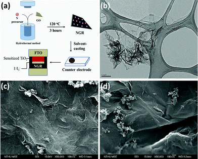 | ||
| Fig. 1 (a) Illustration of the process used to fabricate the NGR counter electrode on fluorinated-doped tin oxide (FTO). (b) TEM image of NGR prepared using the hydrothermal method. (c) SEM images of the morphology of the as-prepared NGR counter electrode. (d) SEM images of the morphology of the counter electrode fabricated using GR. | ||
Fig. 1(b) shows that the morphology of NGR was characterized by a wrinkled, rough surface, with an area of 1.35 μm × 0.8 μm. This small size (compared to the sizes of GR and graphene oxide (GO) (Fig S3†)) may have resulted from the increased strain on the surface of graphene because of the repair of the conjugation system on the surface of GR, which may have caused a slight aggregation. Fig. 1(c) and 1(d) show the morphologies of the counter electrodes fabricated using NGR and GR, respectively. Because of the higher internal strain at the basal plane of GR, the SEM images show a slightly higher degree of surface roughness in the NGR electrode compared to the GR electrode, which is consistent with the results of TEM of NGR. Similar results were also observed when measuring using AFM (Fig. S5†). This is likely due to the incorporation of a lone-pair electron on the nitrogen atom into the conjugation system. In addition, the incorporation of nitrogen into the electrical structure of GR could extend the delocalization of the π electron domains, producing a “healing” effect. This result also implies that the NGR electrode had a high surface area, thereby increasing the exchange current density at the counter electrode surface/electrolyte interface when it served as a catalyst in the DSSC.
In the present study, we focused on the surface composition of GO, GR, and NGR, and attempted to elucidate the effect of the structure on the characteristics of the material by inspecting the X-ray photoelectron spectra (XPS) produced in each case (details in the ESI†). Fig. 2(a) shows the C1s peak of GO, GR, and NGR, indicating the carbon-related functional groups and composition of the structure.11 The XPS spectra of NGR show that a proportion of the C–O–C groups were converted to C–N groups, indicating that the high reduction ability (represented by the spectral peak at 284.8 eV) shifted to a higher binding energy regarding the C![[double bond, length as m-dash]](https://www.rsc.org/images/entities/char_e001.gif) C peak of GR (284.4 eV); this highlights the increase in disorder in the electrical structure of GR that resulted from the incorporation of nitrogen. However, according to the CC peak for NGR and GR, the percentage of CC functional groups increased; this indicated that the range of the delocalized domains increased, which improved the conductivity of the basal plane in GR. Fig. 2(b) shows three functional-related peaks in the deconvoluted spectra for NGR, namely pyrrollic N (398.53 eV), pyridinic N (399.71 eV), and graphitic N (400.91 eV).17 These results confirm that nitrogen atoms were introduced into the GR structure. The C1s peak in the XPS spectrum for NGR shows that the delocalization of π-electrons was increased by the incorporation of nitrogen atoms, which is consistent with the Raman spectra (Fig. 2(c)). However, this finding seems to be in contrast to the general belief that an increased percentage of CC groups should produce a repaired carbon-based molecular structure. According to the Raman spectra, the D:G ratio was smaller for NGR than for GR. This indicates the possibility that the nitrogen atoms provided free electrons (lone-pair) to fill the gaps in the electrical structure of GR, thereby repairing the conjugation system. At the same time, the electroreactive sites were maintained, and were therefore able to provide the required electrocatalytic properties and electrical conductivity.
C peak of GR (284.4 eV); this highlights the increase in disorder in the electrical structure of GR that resulted from the incorporation of nitrogen. However, according to the CC peak for NGR and GR, the percentage of CC functional groups increased; this indicated that the range of the delocalized domains increased, which improved the conductivity of the basal plane in GR. Fig. 2(b) shows three functional-related peaks in the deconvoluted spectra for NGR, namely pyrrollic N (398.53 eV), pyridinic N (399.71 eV), and graphitic N (400.91 eV).17 These results confirm that nitrogen atoms were introduced into the GR structure. The C1s peak in the XPS spectrum for NGR shows that the delocalization of π-electrons was increased by the incorporation of nitrogen atoms, which is consistent with the Raman spectra (Fig. 2(c)). However, this finding seems to be in contrast to the general belief that an increased percentage of CC groups should produce a repaired carbon-based molecular structure. According to the Raman spectra, the D:G ratio was smaller for NGR than for GR. This indicates the possibility that the nitrogen atoms provided free electrons (lone-pair) to fill the gaps in the electrical structure of GR, thereby repairing the conjugation system. At the same time, the electroreactive sites were maintained, and were therefore able to provide the required electrocatalytic properties and electrical conductivity.
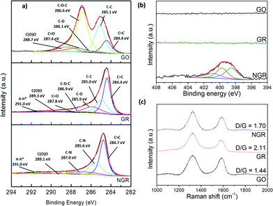 | ||
| Fig. 2 (a) The C1s peak in the XPS spectra of GO, GR, and NGR. (b) The N1s peak in the XPS spectra of GO, GR, and NGR. (c) Raman spectra of GO, GR, and NGR, with the corresponding D:G ratios. | ||
According to the CV results (Fig. 3(a)) for the GR, NGR, and Pt film electrodes, the carbonaceous electrodes exhibited a high current density (because of their high specific surface area). In addition, the NGR electrode exhibited higher current densities than other electrodes because of its high specific surface area and high incidence of defects. Fig. 3(b) shows the diffusion limitations of the redox reaction for various counter electrodes. Compared with Pt films, this result shows that the adsorption of iodide ions had a slight effect on the redox reaction for the NGR material, and implied that the NGR electrodes exhibited stable catalytic behavior for redox species. The anodic peak for the NGR electrode (which was attributed to the oxidation reaction 2I− → I3− + 2e−) indicated a current density similar to that of the GR electrode, implying that the oxidation reaction was maintained, despite the incorporation of the nitrogen atoms. However, the cathodic peak for the NGR electrode (assigned to the reduction reaction I3− + 2e− → 2I−) suggested a higher current density than that of the GR electrode. In addition, compared with Pt films (340 mV), similar peak separations (ΔEp) were found for the peaks of GR (583 mV) and NGR (581 mV); this showed that the redox species selectivity of the NGR's electrocatalytic properties was improved by the incorporation of nitrogen atoms, although GR exhibited a low rate of reduction.
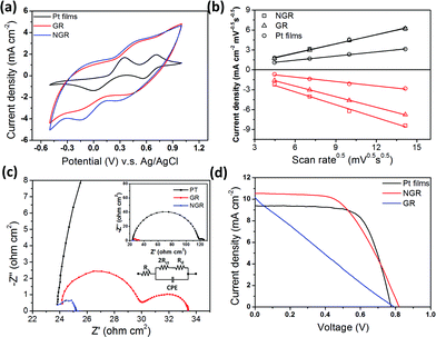 | ||
| Fig. 3 (a) Cyclic voltammograms for Pt film, GR, and NGR electrodes, taken with a scan rate of 50 mV s−1, in a 10 mM LiI and 1 mM I2 acetonitrile solution, containing 0.1 M LiClO4. (b) Plot showing the correlation between current density and scan rate, for the different materials. (c) Impedance spectra of symmetrical cells, taken from 106 Hz to 10−1 Hz. The insets show the equivalent circuit of the device (left), and an expanded view of the GR and NGR spectra (right). (d) Photocurrent density–voltage characteristics of the DSSC fabricated using Pt films, GR, and NGR counter electrodes. | ||
Fig. 3(c) shows Nyquist plots for various symmetrical devices fabricated using carbonaceous electrodes. The charge transfer resistance (RCT) is correlated with the exchange current density (J0), whereas the triiodide is reduced to iodide at the counter electrode. The charge transfer resistance of NGR was lower than that of Pt films or GR. The exchange current density was calculated from the charge transfer resistance using the following equation:18
 | (1) |
where R, T, n, and F represent the gas constant, temperature, number of electrons transferred in the reduction reaction, and Faraday constant, respectively. This finding implies that the process of the charge transfer was faster on the surface of NGR than on the surface of other catalysts; it is likely that this resulted from the higher exchange current density, in agreement with the CV results. Because of its high density of electroreactive sites and high electrical conductivity, the charge transfer behavior of the hydrothermally reduced NGR was improved, indicating its potential as an alternative for Pt catalysts.
The cell performance of the DSSCs was measured using simulated sunlight (1 Sun AM 1.5). Fig. 3(d) and Table 1 show the characteristics of DSSCs fabricated using various different counter electrodes. Under illumination, the DSSC with the NGR counter electrode exhibited a short-circuit photocurrent (Jsc) of 10.55 mA cm−2, an open-circuit voltage (Voc) of 0.82 V, and a fill factor (FF) of 0.55, yielding a conversion efficiency (η) of 4.75%. For the DSSC with the GR counter electrode (which was fabricated using the same method), the values of Voc, Jsc, FF and η were 0.79 V, 10.13 mA cm−2, 0.24 and 1.92%, respectively. The NGR counter electrode therefore showed a marked improvement in photocurrent, compared with the GR counter electrode. The high specific surface area and improved electrocatalytic properties of NGR led to an improved performance, and a decrease in the charge transfer resistance in the DSSC devices. The measured impedance also indicated that the low RCT and low diffusion resistance led to an increase in FF because of the decreased internal resistance of the device.
| Electrode | J sc (mA cm−2) | V oc (V) | FF | η (%) |
|---|---|---|---|---|
| Pt films | 9.37 ± 0.2 | 0.77 ± 0.01 | 0.70 ± 0.01 | 5.03 ± 0.25 |
| GR | 10.13 ± 0.4 | 0.79 ± 0.01 | 0.24 ± 0.05 | 1.92 ± 0.50 |
| NGR | 10.55 ± 0.5 | 0.82 ± 0.02 | 0.55 ± 0.03 | 4.75 ± 0.6 |
The FF of the DSSC prepared using the NGR counter electrode was lower than that of the DSSC prepared using a pristine Pt-film counter electrode. This may have been the result of poor adhesion of the NGR sheets in the small contact area and isolated aromatic domains on the chemically-reduced graphene, which could have led to an increased internal resistance. In addition, the results for the carbonaceous counter electrodes showed that the increased Voc was a result of the decrease in the Fermi level of the redox species.19,20 The DSSCs fabricated using the NGR counter electrode showed a comparable result in performance compared with those fabricated using the platinized counter electrode, showing only a 5.6% decrease in conversion efficiency. By combining the advantages of nitrogen atoms and GR, we achieved both a high density of electroreactive sites and a high specific surface area at the interface, thereby producing a performance identical to that observed for platinized FTO in these experiments.
In conclusion, we have described a nitrogen-doped GR material that can be used as an alternative to platinized FTO in DSSC counter electrodes. Results obtained from XPS and Raman spectra confirmed the hypothesis that doping with nitrogen atoms can produce improvements in the electronic structure of GR, as well as increase the density of electroreactive sites on the surface of GR. Furthermore, CV and EIS results showed that the incorporation of nitrogen into GR improved both the electrocatalytic properties and the exchange current density for selective reduction reactions, thereby achieving a satisfactory electron transfer rate at the interface. The cell performance of DSSCs using a NGR counter electrode reached 94.4% of those prepared using a platinized FTO electrode. This was the result of the increased charge transfer rate and reduced internal resistance produced by the incorporation of the NGR material. Our findings show that nitrogen-doped GR materials have great potential for DSSC-related applications, and merit further investigation.
References
- B. O'Regan and M. Grätzel, Nature, 1991, 353, 737–740 CrossRef CAS.
- T. N. Murakami, S. Ito, Q. Wang, M. K. Nazeeruddin, T. Bessho, I. Cesar, P. Liska, R. Humphry-Baker, P. Comte, P. Pechy and M. Gratzel, J. Electrochem. Soc., 2006, 153, A2255–A2261 CrossRef CAS.
- G. Calogero, F. Bonaccorso, O. M. Marago, P. G. Gucciardi and G. Di Marco, Dalton Trans., 2010, 39, 2903–2909 RSC.
- J. Han, H. Kim, D. Y. Kim, S. M. Jo and S.-Y. Jang, ACS Nano, 2010, 4, 3503–3509 CrossRef CAS.
- G. Veerappan, K. Bojan and S.-W. Rhee, ACS Appl. Mater. Interfaces, 2011, 3, 857–862 CAS.
- J. D. Roy-Mayhew, D. J. Bozym, C. Punckt and I. A. Aksay, ACS Nano, 2010, 4, 6203–6211 CrossRef CAS.
- L. Kavan, J. H. Yum and M. Grätzel, ACS Nano, 2011, 5, 165–172 CrossRef CAS.
- H. Choi, H. Kim, S. Hwang, Y. Han and M. Jeon, J. Mater. Chem., 2011, 21, 7548–7551 RSC.
- G. Zhu, L. Pan, T. Lu, T. Xu and Z. Sun, J. Mater. Chem., 2011, 21, 14869–14875 RSC.
- P. Hasin, M. A. Alpuche-Aviles and Y. Wu, J. Phys. Chem. C, 2010, 114, 15857–15861 CAS.
- M.-Y. Yen, C.-C. Teng, M.-C. Hsiao, P.-I. Liu, W.-P. Chuang, C.-C. M. Ma, C.-K. Hsieh, M.-C. Tsai and C.-H. Tsai, J. Mater. Chem., 2011, 21, 12880–12888 RSC.
- E. Olsen, G. Hagen and S. Eric Lindquist, Sol. Energy Mater. Sol. Cells, 2000, 63, 267–273 CrossRef CAS.
- D. Long, W. Li, L. Ling, J. Miyawaki, I. Mochida and S.-H. Yoon, Langmuir, 2010, 26, 16096–16102 CrossRef CAS.
- Y. Wang, Y. Shao, D. W. Matson, J. Li and Y. Lin, ACS Nano, 2010, 4, 1790–1798 CrossRef CAS.
- Z. Luo, S. Lim, Z. Tian, J. Shang, L. Lai, B. MacDonald, C. Fu, Z. Shen, T. Yu and J. Lin, J. Mater. Chem., 2011, 21, 8038–8044 RSC.
- Y. Shao, S. Zhang, M. H. Engelhard, G. Li, G. Shao, Y. Wang, J. Liu, I. A. Aksay and Y. Lin, J. Mater. Chem., 2010, 20, 7491–7496 RSC.
- D. Wei, Y. Liu, Y. Wang, H. Zhang, L. Huang and G. Yu, Nano Lett., 2009, 9, 1752–1758 CrossRef CAS.
- A. J. Bard and L. R. Faulkner, Electrochemical Methods: Fundamentals and Applications, Wiley, New York, 2001 Search PubMed.
- K. Imoto, K. Takahashi, T. Yamaguchi, T. Komura, J.-i. Nakamura and K. Murata, Sol. Energy Mater. Sol. Cells, 2003, 79, 459–469 CrossRef CAS.
- P. Li, J. Wu, J. Lin, M. Huang, Y. Huang and Q. Li, Sol. Energy, 2009, 83, 845–849 CrossRef CAS.
Footnote |
| † Electronic supplementary information (ESI) available: XRD, TEM images of GO, GR, SEM images of GR electrode, characterization of EIS spectra of GO, GR and NGR, and characterization of XPS spectra of GO, GR, and NGR. See DOI: 10.1039/c2ra00970f |
| This journal is © The Royal Society of Chemistry 2012 |