Impacts of Sn precursors on solution-processed amorphous zinc–tin oxide films and their transistors†
Yunlong
Zhao
,
Guifang
Dong
,
Lian
Duan
*,
Juan
Qiao
,
Deqiang
Zhang
,
Liduo
Wang
and
Yong
Qiu
*
Key Lab of Organic Optoelectronics and Molecular Engineering of Ministry of Education, Department of Chemistry, Tsinghua University, Beijing 100084, China. E-mail: qiuy@mail.tsinghua.edu.cn; duanl@mail.tsinghua.edu.cn; Fax: +86 10 62795137; Tel: +86 10 62782197
First published on 9th May 2012
Abstract
In order to study the impacts of precursors on solution-processed metal oxide films and the performance of their field-effect transistors (FETs), zinc acetate dehydrate and four different Sn precursors – tin(II) 2-ethylhexanoate, tin(IV) acetate, tin(II) chloride and tin(IV) isopropoxide – were utilized to prepare zinc–tin oxide (ZTO) thin films by metal–organic decomposition (MOD) and sol–gel processes. Through systematic analysis of these films and devices, it is demonstrated that Sn precursors, with different molecular geometrical configurations and organic ligands, greatly affect the thickness, density, morphology and composition of the ZTO thin films and, hence, the performance of their FETs. It is worth noting that although all of the ZTO thin films are amorphous, the morphologies of the ZTO thin films yielded from Sn(II) precursors, with RMS values below 0.5 nm, are much better than those yielded from Sn(IV) precursors. The ZTO-FET prepared from Zn(CH3COO)2·2H2O and SnCl2 shows a typical field-effect charge carrier mobility of 1.8 cm2 V−1 s−1, with an on/off current ratio of 6 × 10⁵. Our research also indicates that tin(II) 2-ethylhexanoate and tin(IV) isopropoxide are promising Sn precursors for the fabrication of transistors.
Introduction
Recently, solution-processed oxide semiconductor thin films have attracted a great deal of attention, with the advantages of large area fabrication, simple processing without a vacuum, low cost and high throughput.1–8 As is well-known, metal cations with (n-1)d10ns0 (n ≥ 4) electronic configurations are much different from the Si lattice, which is composed of covalent bonds among sp3+ hybridized orbitals.1,6 Therefore, these metal oxide semiconductors, which have conduction band states derived from metal s-orbitals, are relatively insensitive to the presence of structural disorder.4 As a result, the amorphous metal oxide films could be candidates for active semiconductor layers with high charge carrier mobility.The Zn/Sn/O ternary system is one of the most promising heterometal-containing semiconducting materials. As a second component, tin has great advantages of vast abundance, low price, transparent character and high solubility in ZnO lattice, which could be attributed to the similar ionic radii of Sn4+ (0.071 nm) and Zn2+ (0.074 nm).5 Solution-processed zinc–tin oxide (ZTO) based field-effect transistors (FETs) with charge carrier mobilities (μFE) of 0.1–33 cm2 V−1 s−1 and on/off ratios (Ion/off) of 103–108 have been reported in recent years.1–3,5,6,9–19 However, it is noticed that high performance devices were always fabricated under high temperatures or with complex processes. Accordingly, lots of research has focused on studying and optimizing the influence factors of solution-processed oxide semiconductors, such as the thermal treatment temperature and atmosphere (i.e., O2, O3, H2O, air and vacuum),3,4,9,20–22 the incorporation of different elements (i.e., In, Ga, Sn, Hf, La, Mg, Al, Zr and Si),1,10,20,22,23 as well as the post-annealing process.20 However, the impacts of metal precursors on the properties of metal oxides and their transistors were seldom systematically discussed.
For a certain metal oxide, the main differences among the precursor materials are the molecular geometrical configuration and the organic ligand.24,25 The choice of the precursors dictates the solution chemistry and, hence, the characteristic of the final metal oxides and the performance of their field-effect transistors. The interactions between the starting reagents during solution synthesis mainly depend on the reactivity of the chemical compounds and preparation conditions of the precursor solution.26 The solution preparation routes utilized in chemical solution deposition film fabrication can be divided into two principal categories: metal–organic decomposition (MOD) and sol–gel processes.26–28 The MOD routes usually use water-insensitive metal carboxylate compounds and thermal decomposition was followed by coating of an organic precursor solution on a substrate to form the final desired materials.26,27 The sol–gel process is based on the hydrolysis and condensation of molecular precursors and offers a lower processing temperature. Metal alkoxides and metal chlorides, which are water-sensitive, are usually used in the sol–gel processes.26,27
In order to study the impacts of precursors on solution-processed metal oxide films and the performance of their field-effect transistors, we focus on Sn precursors and Sn-containing metal oxides in this paper. Sn is a multivalent metallic element and there are proper Sn(II) compounds and Sn(IV) compounds with different molecular geometrical configurations and organic ligands. In addition to the valence, compounds that have undergone different solution preparation routes and compounds with different ligands (rigid or flexible) should be selected to investigate the impacts of Sn precursors.
In our experiments, two kinds of Sn(II) precursors, tin(II) 2-ethylhexanoate and tin(II) chloride, and two kinds of Sn(IV) precursors, tin(IV) acetate and tin(IV) isopropoxide, were employed. Sn carboxylates, including tin(II) 2-ethylhexanoate and tin(IV) acetate, undergo the MOD route, which decompose directly. The Sn alkoxides or chlorides, including tin(II) chloride and tin(IV) isopropoxide, undergo the sol–gel process, which will get rid of the organic residues after hydrolysis and condensation reactions.26,29 Furthermore, according to the best of our knowledge, it's the first time that tin(II) 2-ethylhexanoate and tin(IV) isopropoxide were used as Sn precursors to fabricate ZTO transistors. The metal vaporization loss, thickness, density, morphology and composition of the ZTO films, as well as the device performance of the ZTO-FETs have been explored and it was found that they were affected by Sn precursors greatly.
Experimental
All of the reagents, including zinc acetate dehydrate (Zn(CH3COO)2·2H2O, 98+%), tin(II) 2-ethylhexanoate (Sn(C8H15O2)2, 99.5%), tin(IV) acetate (Sn(CH3COO)4, 99%), tin(II) chloride (SnCl2, 98%), tin(IV) isopropoxide (Sn(OC3H7)4, 98.5%), ethanolamine (NH2CH2CH2OH, 99%) and 2-methoxyethanol (CH3OCH2CH2OH, 99.8%), were purchased from Alfa Aesar without additional purification. The metal precursor solution for fabricating ZTO film was prepared by dissolving zinc acetate dehydrate and Sn precursor salt in 2-methoxyethanol separately. Then, ethanolamine was added as the stabilizing agent to improve the solubility of precursor salts.11 The concentrations of Zn(CH3COO)2·2H2O, Sn precursor and ethanolamine in the precursor solutions were kept at 0.30M, 0.15M and 1.5M, respectively. Four kinds of ZTO precursor solutions were prepared and named precursor solution 1, 2, 3 and 4:Precursor solution 1: 0.30M zinc acetate dehydrate and 0.15M tin(II) 2-ethylhexanoate
Precursor solution 2: 0.30M zinc acetate dehydrate and 0.15M tin(IV) acetate
Precursor solution 3: 0.30M zinc acetate dehydrate and 0.15M tin(II) chloride
Precursor solution 4: 0.30M zinc acetate dehydrate and 0.15M tin(IV) isopropoxide.
The total concentration of metal precursors was kept at 0.45M and the stoichiometric ratio of Sn and Zn was 0.5 for every precursor solution. Prior to spin-coating, the precursor solutions were all stirred for 8 h at room temperature and then filtered through a 0.22 μm JN filter. Then, the spin coating was performed at a spin speed of 3000 r·min−1 for 30 s. ZTO thin films were obtained after thermal treatment at 450 °C for 30 min in the atmosphere and the film thickness was measured by scanning electron microscopy (SEM, HITACHI, S-4500). Here, the ZTO thin films derived from precursor solutions 1, 2, 3 and 4 were named ZTO 1, 2, 3 and 4, respectively.
The thermal properties of the Sn and Zn precursors were determined by thermogravimetric analysis (TGA, TA Instruments, Q5000 IR). The morphology of the ZTO films was characterized with an atomic force microscope (AFM, Seiko, SPA400). The composition of the ZTO films was determined by Auger electron spectroscopy (AES, ULVAC-PHI, PHI-700) and X-ray photoelectron spectroscopy (XPS, ULVAC-PHI, PHI Quantera SXM), and the crystallinity of the ZTO films was determined by X-ray diffraction (XRD, D/max-IIIA 3KW, Cu-Kα) using a fixed glancing incidence angle (0.5°). The viscosity data of the ZTO precursor solutions were measured by a viscometer (BROOKFIELD, LVDV-III+CP) at room temperature. The densities of ZTO films were measured by the X-ray reflectometry (XRR) which was taken on an X-ray diffractometer (Bruker D8 Discover) at a wavelength of 0.154 nm (Cu-Kα radiation).
For the FETs, the source and drain electrodes were indium tin oxide (ITO) with a sheet resistance of 7 Ω/□. The channel length was 100 μm and the channel width was 1000 μm. After the ZTO films were formed on the ITO substrate, poly(methyl methacrylate) (PMMA) was deposited by spin coating on the ZTO layer as the insulating layer with a thickness of 500 nm. The gate electrode, silver (Ag), was deposited on the PMMA layer by a conventional evaporation method in a vacuum through a shadow mask. The performance of the ZTO-FETs was measured with a semiconductor characterization system (Keithley, 4200 SCS) in air.
Results and discussion
Properties of Sn and Zn precursors
The main differences between the Sn salts are based on the valence state of Sn atom, the molecular geometrical configuration and the properties of the ligands. Solubility and stability in precursor solution are important in the fabrication of the ZTO thin films by sol–gel process and these mainly depend on the ligands.25Fig. 1 shows the structures of the metal salts, including the chemical structure of the ligands. According to our study, the solubility of Sn(C8H15O2)2, which is liquid, is much better than the others. It can be dissolved in 2-methoxyethanol easily with high concentration and the solution is very stable in air due to its flexible alkyl chain. The flexible alkyl chain could increase the cross-linking reactions between Zn and Sn species in the starting solutions, which will avoid the phase separation in the final oxides.25 However, the solubility of Sn(OC3H7)4 is awful due to its rigid ligand.29 Its saturation concentration in 2-methoxyethanol is only about 0.16 M, as obtained from our experiment.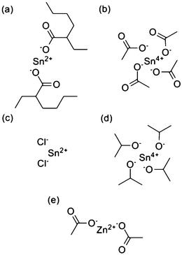 | ||
| Fig. 1 Structures of (a) Sn(C8H15O2)2, (b) Sn(CH3COO)4, (c) SnCl2, (d) Sn(OC3H7)4 and (e) Zn(CH3COO)2. | ||
It is well-known that the hydrolysis and condensation reactions of dissolved Sn alkoxides or chlorides are very fast and adding sufficient ethanolamine is necessary to avoid precipitation and allow sol and gel formation.29 In comparison, Sn carboxylates are more stable and water-insensitive in solution, even without stabilizers.26
Thermal decomposition of Sn and Zn precursors
Decomposition reactions are inevitable to obtain metal oxides from the metal precursors.20 The precursors were heated from 35 °C to 600 °C under air, using a heating rate of 10 K min−1. After heating, yellow powders were obtained. There are two mechanisms for the Sn and Zn precursors. The Sn and Zn carboxylates, including Sn(C8H15O2)2, Sn(CH3COO)4 and Zn(CH3COO)2·2H2O, undergo the MOD route, which decompose directly. The Sn alkoxides or chlorides, including SnCl2 and Sn(OC3H7)4, undergo the sol–gel process, which should get rid of the organic residues after hydrolysis and condensation reactions.26,29Fig. 2 shows the thermal behaviours of the Sn and Zn precursors. It was found that the formation of metal oxide for Sn(C8H15O2)2, Sn(CH3COO)4, SnCl2, Sn(OC3H7)4 and Zn(CH3COO)2·2H2O occurred at 90–310 °C, 35–352 °C, 320–430 °C, 35–300 °C and 180–295 °C, respectively. Therefore, the combinations of Sn(C8H15O2)2, Sn(OC3H7)4 and Zn(CH3COO)2·2H2O are proved to be candidates for preparing ZTO thin films at low temperature.
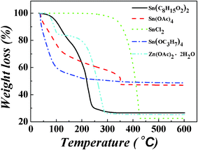 | ||
| Fig. 2 TGA curves of Sn(C8H15O2)2, Sn(CH3COO)4, SnCl2, Sn(OC3H7)4 and Zn(CH3COO)2·2H2O. | ||
As shown in Table 1, there is a remarkable variation between the experimental and calculated remaining masses for Sn(C8H15O2)2, SnCl2 and Zn(CH3COO)2·2H2O. This means that not only are the organic groups lost during thermal treatment process, but also some volatiles containing of Sn or Zn. The metal atom loss proportions of Sn(C8H15O2)2, SnCl2 and Zn(CH3COO)2·2H2O were calculated to be 28.5%, 71.7% and 32.0%, respectively, while the calculated remaining masses of Sn(CH3COO)4 and Sn(OC3H7)4 are a little larger than the experimental remaining masses (seen in Table 1). The reason might be that there is a large amount of remaining impurities11 and the oxidation in the ZTO films is incomplete. According to the TGA curves and metal atom loss proportions of the precursors, it is noted that the faster the degradation occurs, the more the metal atom loses.
| Molecular weight | Remaining mass | Calculated remaining mass | |
|---|---|---|---|
| Sn(C8H15O2)2 | 405.1 | 26.6% | 37.2% |
| Sn(CH3COO)4 | 354.7 | 47.0% | 42.5% |
| SnCl2 | 189.7 | 22.5% | 79.4% |
| Sn(OC3H7)4 | 354.7 | 48.8% | 42.5% |
| Zn(CH3COO)2·2H2O | 219.2 | 25.3% | 37.2% |
However, it is well-known that solution-derived oxide thin films had the advantage of easy controlling the composition by changing the stoichiometric ratio of the starting materials.26,28 Our experimental results demonstrate that the Zn and Sn will be lost during thermal treatment and different metal precursors have different metal atom loss proportions, indicating that the Sn/Zn ratio in the ZTO films varies gradually during the thermal treatment process. The metal loss process during thermal treatment has been reported before.5 Matthias Driess et al. synthesized two heterobimetallic alkyl-(trimethylstannoxy) zinc clusters and found that the loss rate of Sn atoms during the annealing process increased with the increase of heating rate and heating time.5 Our experimental results show that different metal precursors have different metal atom loss proportions under the same heating conditions. The metal atom loss proportions also depend on the rate of the thermal degradation.
The thickness, density and morphology of the ZTO films
The impacts of Sn precursors on the ZTO thin films were explored to find out the relationship between the metal salts and their metal oxide films. The viscosity values of ZTO precursor solutions, thickness, densities and morphologies of the ZTO films, were measured, shown in Table 2. The viscosity value of precursor solution 3 is smaller than the others, which is because of it having the smallest molecular weight and the weakest Van Der Waals force between molecules. The differences in thickness and densities between the ZTO films are related to the different molecular structures and the metal atom loss proportions of the Sn precursors.| η a (m·Pa·s) | ρ b(g cm−3) | d c (nm) | Morphology of ZTO films | ||
|---|---|---|---|---|---|
| P–Vd (nm) | RMSe (nm) | ||||
| a The viscosity data of the ZTO precursor solutions (measured at 25 °C). b Densities of the ZTO films. c Thickness of the ZTO films. d Peak-valley value. e The root mean square value. | |||||
| ZTO 1 | 3.38 | 3.71 | 29.0 ± 2.8 | 13.7 | 0.4 |
| ZTO 2 | 3.52 | 4.40 | 36.1 ± 3.2 | 7.3 | 0.5 |
| ZTO 3 | 2.95 | 4.22 | 25.3 ± 2.9 | 2.9 | 0.2 |
| ZTO 4 | 3.42 | 4.72 | 33.5 ± 3.3 | 16.9 | 1.0 |
As shown in Fig. 3, the morphologies of ZTO 1 and ZTO 3 are much different from the morphologies of ZTO 2 and ZTO 4. The surfaces of ZTO 1 and ZTO 3 are both smooth and dense with RMS values below 0.4 nm. However, pinholes are observed in the surfaces of ZTO 2 and ZTO 4. It is noted that the Sn precursors for ZTO 1 and ZTO 3 are both Sn(II) compounds, while the Sn precursors for ZTO 2 and ZTO 4 are both Sn(IV) compounds. We think that this is because the two kinds of Sn compounds have different molecular geometrical configurations.24 The Sn(II) compounds own a quasi-linear structure and the Sn(IV) compounds belong to tetrahedron. All of the ZTO thin films have smooth morphology except ZTO 4; the reason for this may be the bad solubility of Sn(OC3H7)4.
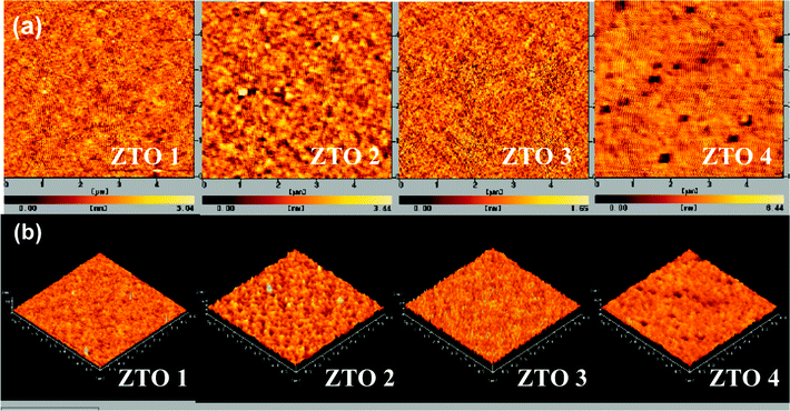 | ||
| Fig. 3 AFM images (5 × 5 μm) of the ZTO thin films: (a) two dimensional; (b) three dimensional. | ||
Crystalline and composition of ZTO films
As shown in Fig. 4, all of the XRD patterns exhibit a single, extremely broad peak at 2θ ≈ 34°, which is characteristic of amorphous zinc tin oxide films.30,31 It means that the precursors have little impact on the crystallinity of the ZTO films in these preparation conditions. This is because the crystallinity is usually controlled by the preparation conditions;30 thereby, the ZTO films are all amorphous with different Sn precursors.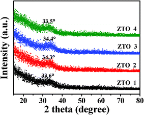 | ||
| Fig. 4 Glance angle XRD patterns of the ZTO films, using Cu-Kα radiation (0.5° incident angle). | ||
Fig. 5 shows the XPS spectra of Zn, Sn and O ions in the ZTO films. Here, Zn 2P3/2 centered at 1021.8 eV indicates the Zn–O bond and the Sn 3d5/2 centered at 486.6 eV indicates the Sn–O bond.32 The O 1s region of the XPS spectra was divided into three obvious peaks centered at 532.3 eV, 531.7 eV and 530.3 eV.33 The binding energy peak at 530.3 eV is attributed to O2− ions surrounded by Zn and Sn atoms.10,32,34 The binding energy peak at 531.7 eV is associated with O2− ions in the vacancy oxygen in ZTO.10,32,35 The binding energy peak at 532.3 eV is associated with O2− ions in the hydroxide in ZTO.10,32,35 As shown in Table 3, the fractions of lattice oxygen (530.3 eV), vacancy oxygen (531.7 eV) and metal hydroxide oxygen (532.3 eV) were calculated from the XPS semiquantitative analysis.33 The contents of oxygen vacancies in ZTO 3 and ZTO 4 films are more than the others and the contents of metal hydroxide oxygen in ZTO films yielded from Sn(II) precursors are a little lower than those yielded from Sn(IV) precursors.
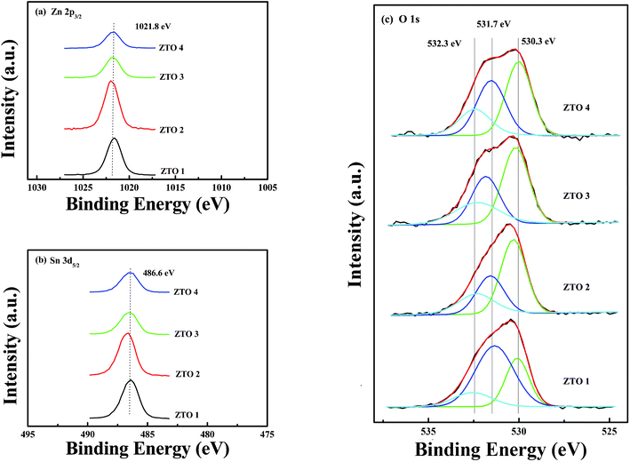 | ||
| Fig. 5 Core-level XPS spectra of the ZTO thin films: (a) XPS Zn 2P3/2 spectra; (b) XPS Sn 3d5/2 spectra; (c) XPS O 1s spectra with sub-peaks due to chemical contribution of lattice oxygen (530.3 eV), vacancy oxygen (531.7 eV) and metal hydroxide oxygen (532.3 eV). | ||
| OM–O–M (%) | Ovac (%) | OM–OH (%) | Sn/Zn | ZTO-FET performances | ||||||
|---|---|---|---|---|---|---|---|---|---|---|
| μ FE (cm2 V−1 s−1) | I on/off | I off (A) | V th (V) | S (V/dec.) | N trap (cm−2) at 25 °C | |||||
| ZTO 1 | 47.0 | 32.2 | 20.8 | 0.60 | 1.1 ± 0.2 | 5 × 10⁵ | 1.6 × 10⁻⁹ | 16.3 ± 2.1 | 3.26 | 3.2 × 10¹² |
| ZTO 2 | 50.4 | 27.0 | 22.5 | 0.44 | 0.6 ± 0.1 | 2 × 10⁵ | 1.1 × 10⁻⁹ | 23.1 ± 4.2 | 3.57 | 3.5 × 10¹² |
| ZTO 3 | 46.7 | 33.1 | 20.2 | 0.48 | 1.8 ± 0.3 | 6 × 10⁵ | 5.4 × 10⁻¹⁰ | 48.0 ± 5.5 | 3.83 | 3.8 × 10¹² |
| ZTO 4 | 43.2 | 34.3 | 22.4 | 0.42 | 1.1 ± 0.3 | 4 × 10⁴ | 1.2 × 10⁻⁸ | 32.4 ± 3.1 | 7.76 | 7.7 × 10¹² |
The compositions of the ZTO films were determined by Auger electron spectroscopy (AES) and the ratios of Zn, Sn and O in the bulk of the ZTO thin films (sputtered 15 nm) were measured, shown in Fig. S3†. For ZTO 1, 2, 3 and 4, the Sn/Zn ratios are not 0.50, the theoretic Sn/Zn ratio, but 0.60, 0.44, 0.48 and 0.42, respectively. This is another proof for the existence of metal atom loss during thermal treatment. It is also demonstrated that controlling the composition accurately by changing the stoichiometric ratio of the starting materials is very difficult without considering metal atom loss proportions under high temperatures.
Performances of the transistors based on ZTO thin films
The solution-processed amorphous ZTO films were fabricated as active layers in the FETs. In this study, bottom-contact top-gate FET devices were designed, as shown in Fig. 6(c). Here, the PMMA layer has a dielectric constant of 3.2.36Fig. 6(a) shows the transfer characteristics of FETs based on ZTO films. As predicted, the ZTO layers showed the typical electrical characteristics of an n-channel transistor. The output characteristics of FETs based on ZTO 1, ZTO 2, ZTO 3 and ZTO 4 are shown in Fig. S4†. The transistors based on ZTO 1, ZTO 2, ZTO 3 and ZTO 4 were well-modulated depending on the gate voltage and exhibited clear saturation behavior with typical device performances.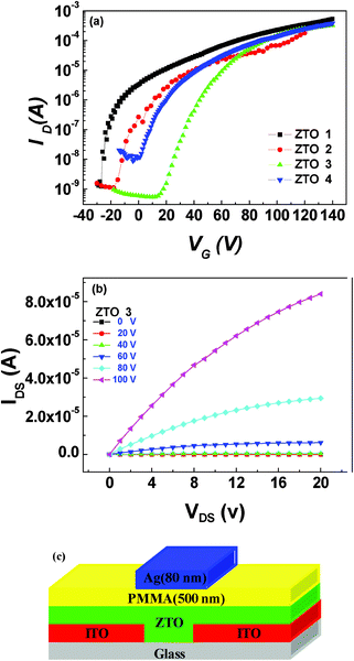 | ||
| Fig. 6 Electronic characteristics and device structure of the ZTO FETs: (a) transfer characteristics of FETs based on ZTO 1, ZTO 2, ZTO 3 and ZTO 4; (b) output characteristics of FETs based on ZTO 3; (c) device structure of the ZTO-FETs. | ||
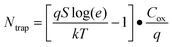
The performance of the ZTO FETs was summarized in Table 3. It was found that the Sn precursors affected the field-effect charge carrier mobility (μFE), off current (Ioff), sub-threshold slope (S) and maximum interfacial trap density (Ntrap). Here, the sub-threshold slope (S) and maximum interfacial trap density (Ntrap) are calculated from13,37:
| S = dVG/d(logID) (VG < Vth) |
 | (1) |
According to previous reports,1,33,38 the electrical performance of the oxide semiconductor is critically determined by the oxygen vacancy, the hydroxides in oxide films and the chemical composition and structure of metal oxide systems. With different Sn precursors, the ZTO films here show different characteristics for contents of oxygen vacancies and metal hydroxide oxygen, as well as the Sn/Zn ratios of the ZTO films, as can be seen in Table 3. Therefore, the charge carrier mobility, off current, sub-threshold slope and interfacial trap density of these ZTO FETs are greatly affected by the variation of Sn precursors. As Jooho Moon et al. reported,33 a chemical structure with more oxygen vacancies and less hydroxides will improve the device mobility significantly, which means that the device mobility could be controlled by changing the contents of oxygen vacancies and hydroxides in oxide films. The mobilities of these ZTO FETs are perfectly consistent with this theory. ZTO 3 shows the highest mobility of 1.8 cm2 V−1 s−1 due to its high content of oxygen vacancies and low content of hydroxides. While, with a low content of oxygen vacancies and a high content of hydroxides, ZTO 2 shows the lowest mobility of 0.6 cm2 V−1 s−1. ZTO 1 and ZTO 4 show moderate mobilities around 1.1 cm2 V−1 s−1 for the same reasons.
The Sn atom loss proportion of tin(II) 2-ethylhexanoate is lower and, as a result, the Sn/Zn ratio in ZTO 1 could reach 0.60, which is much larger than the others. The high Sn content makes a significant contribution to its high content of oxygen vacancies.1
The interfacial trap density is an important parameter, which is affected by the morphology and carrier concentration of active layers and the resistivity values.39,40 The maximum interfacial trap densities for ZTO 1, 2 and 3 are about 3 × 1012 cm−2, due to their smooth morphologies, while the maximum interfacial trap density for ZTO 4 is larger because of its poor morphology. The poor morphology of ZTO 4 could affect the subsequent fabrication of solution-processed PMMA layer and, hence, the interface of ZTO/PMMA.41
The off current is mainly determined by the carrier concentration of the active layer and the content of oxygen vacancy affects the carrier concentration critically.42,43 The off current of the FET based on ZTO 4 reached 1.2 × 10⁻⁸ A, which was an order of magnitude larger than the other three. This is mainly caused by the high content of oxygen vacancies in ZTO 4 films.
Tin(II) 2-ethylhexanoate and tin(IV) isopropoxide were used as Sn precursors for the first time in the fabrication of ZTO based transistors, according to the best of our knowledge. Tin(II) 2-ethylhexanoate have the advantages of good solubility and stability in solution, high quality film-forming ability and a low metal atom loss proportion after annealing. Thus, it is suitable for commercial production. Meanwhile, for tin(IV) isopropoxide, in spite of its poor solubility, poor morphology and high content of hydroxides, the FET derived from it reached a moderate field-effect charge carrier mobility of 1.1 cm2 V−1 s−1. In addition, the decomposition temperature of tin(IV) isopropoxide is the lowest, which is lower than 200 °C (seen in Fig. 2), compared with the others. Thus, it is believed that tin(IV) isopropoxide could be a potential precursor for low temperature fabricated oxide semiconductor films.
Conclusions
In summary, four ZTO-based FETs derived from four ZTO precursor solutions by spin coating, were fabricated and the impacts of Sn precursors on solution-processed ZTO films and the performance of their transistors were systematically studied. The main differences between the precursor materials are the molecular geometrical configuration and the organic ligand. The morphologies, structural and electronic characteristics of the ZTO films were sensitive to the Sn precursors due to their different solubilities and reactivities, different solution preparation routes, as well as decomposition processes. The thickness of the ZTO films was positively related to the viscosity of the precursor solution. The composition depended on the chemical structures and decomposition process of precursors. The charge carrier mobility, off current, sub-threshold slope and interfacial trap density were hence affected by the variation of Sn precursors.It was also found that the Sn/Zn ratios in the ZTO films varied during the thermal treatment process and were different from the stoichiometric ratio of the starting materials. The reason was that there was metal atom loss and the proportion depended on not only the heating time and heating rate, but also the precursor itself. Our work may shed light on the impacts of metal precursors on solution-processed metal oxides and the performance of their transistors.
Acknowledgements
This research was supported by the National Natural Science Foundation of China (Grant No. 50990060 and 61177023) and the National Key Basic Research and Development Program of China (Grant No. 2009CB930602 and 2009CB623604).References
- K. Dong Lim and K. Hyun Jae, Proc. of SPIE, 2010, 7603, 760313 Search PubMed.
- B. N. Pal, B. M. Dhar, K. C. See and H. E. Katz, Nat. Mater., 2009, 8, 898 CrossRef CAS.
- M. G. Kim, M. G. Kanatzidis, A. Facchetti and T. J. Marks, Nat. Mater., 2011, 10, 382 CrossRef CAS.
- K. K. Banger, Y. Yamashita, K. Mori, R. L. Peterson, T. Leedham, J. Rickard and H. Sirringhaus, Nat. Mater., 2011, 10, 45 CrossRef CAS.
- M. Tsaroucha, Y. Aksu, E. Irran and M. Driess, Chem. Mater., 2011, 23, 2428 CrossRef CAS.
- K. Song, D. Kim, X. S. Li, T. Jun, Y. Jeong and J. Moon, J. Mater. Chem., 2009, 19, 8881 RSC.
- H. Frenzel, A. Lajn, H. von Wenckstern, M. Lorenz, F. Schein, Z. P. Zhang and M. Grundmann, Adv. Mater., 2010, 22, 5332 CrossRef CAS.
- D. H. Lee, Y. J. Chang, G. S. Herman and C. H. Chang, Adv. Mater., 2007, 19, 843 CrossRef CAS.
- Y. L. Zhao, L. A. Duan, J. A. Qiao, D. Q. Zhang, G. F. Dong, L. D. Wang and Y. Qiu, Sci. China: Chem., 2011, 54, 651 CrossRef CAS.
- R. You Seung, K. Dong Lim, J. Woong Hee and K. Hyun Jae, Appl. Phys. Lett., 2010, 233502 Search PubMed.
- S. Jeong, J. Y. Lee, S. S. Lee, Y. Choi and B. H. Ryu, J. Phys. Chem. C, 2011, 115, 11773 CAS.
- H. Yu, H. Lee, J. Lee, H. Shin and M. Lee, Microelectron. Eng., 2011, 88, 6 CrossRef CAS.
- K. H. Kim, Y. H. Kim, H. J. Kim, J. I. Han and S. K. Park, IEEE Electron Device Lett., 2011, 32, 524 CrossRef CAS.
- K. Yong-Hoon, K. Kwang-Ho, O. Min Suk, K. Hyun Jae, H. Jeong In, H. ; Min-Koo and P. Sung Kyu, IEEE Electron Device Lett., 2010, 31, 836 CrossRef.
- Y. Jeong, C. Bae, D. Kim, K. Song, K. Woo, H. Shin, G. Z. Cao and J. Moon, ACS Appl. Mater. Interfaces, 2010, 2, 611 CAS.
- P. Sung Kyu, K. Yong-Hoon, K. Hyun-Soo and H. Jeong-In, Electrochem. Solid-State Lett., 2009, H256 Search PubMed.
- S. Seok-Jun, C. Chaun Gi, H. Young Hwan and B. Byeong-Soo, J. Phys. D: Appl. Phys., 2009, 035106 Search PubMed.
- S. Dutta and A. Dodabalapur, Sens. Actuators, B, 2009, 143, 50 CrossRef.
- S. Jeong, Y. Jeong and J. Moon, J. Phys. Chem. C, 2008, 112, 11082 CAS.
- Y. H. Hwang, J. H. Jeon and B. S. Bae, Electrochem. Solid-State Lett., 2011, 14, H303 CrossRef CAS.
- S. Y. Han, G. S. Herman and C. H. Chang, J. Am. Chem. Soc., 2011, 133, 5166 CrossRef CAS.
- K. Dae Woong, K. Jang Hyun, C. Ji Soo, K. Sang Wan, K. Wandong, P. Jae Chul, S. Ihun, K. Chang Jung, U. I. Jung and P. Byung-Gook, Appl. Phys. Lett., 2011, 98, 063502 CrossRef.
- E. Chong, K. Seung Han and L. Sang Yeol, Appl. Phys. Lett., 2010, 252112 Search PubMed.
- V. G. Kessler, J. Sol-Gel Sci. Technol., 2004, 32, 11 CrossRef CAS.
- M. Epifani, R. Diaz, J. Arbiol, P. Siciliano and J. R. Morante, Chem. Mater., 2006, 18, 840 CrossRef CAS.
- M. P. M. Bhuiyan and K. Salama, Supercond. Sci. Technol., 2006, 19, R1 CrossRef CAS.
- R. M. Pasquarelli, D. S. Ginley and R. O'Hayre, Chem. Soc. Rev., 2011, 40, 5406 RSC.
- S. Mishra, S. Daniele and L. G. Hubert-Pfalzgraf, Chem. Soc. Rev., 2007, 36, 1770 RSC.
- Y. C. Wu, W. Hamd, E. Thune, A. Boulle, C. Rochas and R. Guinebretiere, J. Non-Cryst. Solids, 2009, 355, 951 CrossRef CAS.
- H. Q. Chiang, J. F. Wager, R. L. Hoffman, J. Jeong and D. A. Keszler, Appl. Phys. Lett., 2005, 86 Search PubMed.
- D. L. Young, H Moutinho, Y. .Yan and T. J. Coutts, J. Appl. Phys., 2002, 92, 310 CrossRef CAS.
- J. F. Moulder , W. F. Stickle , P. E. Sobol and K. D. Bomben, Handbook of X-ray Photoelectron Spectroscopy, Physical Electronics Inc., Minesota, 1995 Search PubMed.
- S. Jeong, J.-Y. Lee, S. S. Lee, S.-W. Oh, H. H. Lee, Y.-H Seo, B.-H. Ryu and Y. Choi, J. Mater. Chem., 2011, 21, 17066 RSC.
- M. Chen, Z. L. Pei, C. Sun, L. S. Wen and X. Wang, Mater. Lett., 2001, 48, 194 CrossRef CAS.
- C. Terrier, J. P. Chatelon, R. Berjoan and J. A. Roger, Thin Solid Films, 1995, 263, 37 CrossRef CAS.
- X. Y. Wang, G. F. Dong, J. Qiao, L. D. Wang and Y. Qiu, Chin. J. Inorg. Chem., 2009, 25, 2071 CAS.
- M. McDowell, I. G. Hill, J. E. McDermott, S. L. Bernasek and J. Schwartz, Appl. Phys. Lett., 2006, 88, 073505 CrossRef.
- S. Jeong and J. Moon, J. Mater. Chem., 2012, 22, 1243 RSC.
- B.-Y. Su, S.-Y. Chu and Y.-D. Juang, IEEE Trans. Electron Devices, 2012, 59, 700 CrossRef CAS.
- A. Rolland, J. Richard, J. P. Kleider and D. Mencaraglia, J. Electrochem. Soc., 1993, 140, 3679 CrossRef CAS.
- M.-G. Kim, H. S. Kim, Y.-G. Ha, J. He, M. G. Kanatzidis, A. Facchetti and T. J. Marks, J. Am. Chem. Soc., 2010, 132, 10352 CrossRef CAS.
- K. Gun Hee, J. Woong Hee and K. Hyun Jae, Phys. Status Solidi A, 2010, 207, 1677 CrossRef.
- K. Ide, Y. Kikuchi, K. Nomura, M. Kimura, T. Kamiya and H. Hosono, Appl. Phys. Lett., 2011, 99, 093507 CrossRef.
Footnote |
| † Electronic supplementary information (ESI) available. See DOI: 10.1039/c2ra00764a |
| This journal is © The Royal Society of Chemistry 2012 |