Synthesis and optical properties of chromium-doped spinel hollow nanofibers by single-nozzle electrospinning
Guoping
Dong
*a,
Xiudi
Xiao
b,
Mingying
Peng
a,
Zhijun
Ma
a,
Shi
Ye
a,
Dongdan
Chen
a,
Huijun
Qin
a,
Guangliang
Deng
a,
Qiming
Liang
a and
Jianrong
Qiu
*a
aState Key Laboratory of Luminescent Materials and Devices; and Institute of Optical Communication Materials, South China University of Technology, Guangzhou, Guangdong 510640, PR China. E-mail: dgp@ scut.edu.cn; qjr@scut.edu.cn
bGuangzhou Institute of Energy Conversion, Chinese Academy of Sciences, Guangzhou, Guangdong 510640, PR China
First published on 8th February 2012
Abstract
Novel spinel hollow nanofibers were synthesized by a convenient single-nozzle electrospinning technique. Based on the composition and morphology results by X-ray diffraction (XRD), scanning electron microscopy (SEM) and transmission electron microscopy (TEM), a ‘gas-push’ model was proposed to elucidate the formation mechanism of hollow nanofibers during calcination. Photoluminescence (PL) properties of calcined ZnAl2O4: xCr3+ and MgAl2O4: xCr3+ nanofibers were investigated systematically. Under an excitation of 400 nm or 530–550 nm (4A2g→4T1g or 4A2g→4T2g transitions of Cr3+ ions), an emission band at 675–725 nm including a sharp emission line (R-line) at ∼687 nm with several vibrational sidebands was obtained. Compared with the spectroscopic properties of ZnAl2O4: xCr3+ nanofibers, the emission band was broadened and the decay lifetime was shortened for MgAl2O4: xCr3+ nanofibers. By calculation of crystal field strength, the value of Dq/B is estimated to be 3.25 and 2.72 for ZnAl2O4: xCr3+ and MgAl2O4: xCr3+ nanofibers, respectively. The difference of crystal field strength gives a good explanation of the spectroscopic and decay evolution between ZnAl2O4: xCr3+ and MgAl2O4: xCr3+ nanofibers.
1. Introduction
Light-emitting nanostructured materials with dimensional restriction have attracted much attention due to their applications in panel displays, lighting, lasing, waveguides, sensors, biological markers, etc.1–7 Owing to their superior chemical and thermal stability, oxide-based phosphors have gained more interest compared with other fluorides, sulfides, oxysulfides, etc.8–14 When the size of phosphors is reduced to the nanoscale, the luminescence quantum field and display resolution is expected to be greatly improved. Among various oxide hosts, a spinel (ZnAl2O4 and MgAl2O4) with a face centered cubic (FCC) structure has been shown as an ideal host lattice for transition metal and rare earth ions to generate luminescence with high quantum field.15–18 By the addition of active Cr3+ ions with long lifetime into a spinel host, it is promising to realize high efficiency luminescence, and even lasing output.19,20One dimensional nanostructured materials including nanofibers, nanowires and nanotubes have gained much attention due to their unique anisotropic structure, and can be potentially applied as one dimensional waveguides, polarized light resources, lasers, hydrophobicity, energy conversion, photocatalysts and sensors in micro/nano-devices.21–30 As one of the most versatile and effective techniques to prepare nanofibers, electrospinning has been utilized to prepare a variety of polymer and inorganic nanofibers.29–34 By controlling the precursor solution and electrospun parameters, the morphology, size, microstructure and composition of nanofibers can be conveniently tuned in a wide range. Several typical microstructures (solid, hollow, belt and porous) have been successfully prepared in previous work.19–25,29–37 For the synthesis of hollow nanofibers by electrospinning, almost all previous work has utilized the coaxial bi-nozzle electrospining equipment.38–41 It is necessary to use an immiscible oil as the core precursor solution, which is combusted during calcination to form a hollow nanostructure. Thus, the preparation process of hollow nanofibers becomes complex, and the composition of hollow nanofibers is also restricted by the immiscible oil in the core.
Herein, by utilization of a polymer with a low degree of polymerization and controlling the content of polymer and inorganic salts in the precursor solution, spinel hollow nanofibers were synthesized by single-nozzle electrospinning. A ‘gas-push’ model was proposed to elucidate the formation mechanism of hollow nanofibers. The spectroscopic properties of calcined ZnAl2O4: xCr3+ and MgAl2O4: xCr3+ nanofibers were investigated systematically. By calculation of the crystal field strength of the host, the evolution of photoluminescence (PL) and decay characteristics between ZnAl2O4: xCr3+ and MgAl2O4: xCr3+ nanofibers were well explained.
2. Experimental
2.1 Preparation of spinel nanofibers by electrospinning
Chromium-doped spinel (ZnAl2O4: xCr3+ and MgAl2O4: xCr3+) nanofibers were prepared by electrospinning. Analytical grade Zn(NO3)2·6H2O, Mg(NO3)2·6H2O, Al(NO3)3·9H2O and Cr(NO3)3·9H2O, which were purchased from Sinopharm Chemical Reagent (SCR) Co., Ltd (Shanghai, China), were used as the precursors of Zn, Mg, Al and Cr, respectively. Firstly, 0.86 g Zn(NO3)2·6H2O (or 0.40 g Mg(NO3)2·6H2O) and 2.18 g Al(NO3)3·9H2O were slowly dissolved in 10 mL mixed solution (ethanol–deionized water (in volume) = 3![[thin space (1/6-em)]](https://www.rsc.org/images/entities/char_2009.gif) :1). Secondly, a different amount of Cr(NO3)3·9H2O was dissolved in the above solution. After the inorganic salts were completely dissolved into the transparent solution, 3.75 g poly(vinyl pyrrolidone) (PVP, K-30) was dissolved in the above solution with stirring at room temperature. The homogenous solution was used as the precursor solution for electrospinning. The schematic setup of the electrospinning equipment is similar to our previous work.42,43 The electrospun parameters were optimized as follows: the working distance and voltage was maintained as 12 cm and 20 kV, respectively, and the feeding rate of the solution was fixed at 1.5 mL h−1. A metal roller covered with aluminum foil was used as the collector, and the rotation speed was fixed as 200 rpm. After all the precursor solution had been electrospun, the as-prepared nanofibers were taken off and calcined at 1000, 1100 and 1200 °C for 5 h in air with a heating rate of 200 °C h−1. The designed composition of electrospun nanofibers is ZnAl2O4: xCr3+ (x = 0.005, 0.01, 0.02, 0.03) and MgAl2O4: xCr3+ (x = 0.01, 0.02, 0.03), respectively. The calcined nanofibers were used for morphology, microstructure and spectroscopic properties characterization.
:1). Secondly, a different amount of Cr(NO3)3·9H2O was dissolved in the above solution. After the inorganic salts were completely dissolved into the transparent solution, 3.75 g poly(vinyl pyrrolidone) (PVP, K-30) was dissolved in the above solution with stirring at room temperature. The homogenous solution was used as the precursor solution for electrospinning. The schematic setup of the electrospinning equipment is similar to our previous work.42,43 The electrospun parameters were optimized as follows: the working distance and voltage was maintained as 12 cm and 20 kV, respectively, and the feeding rate of the solution was fixed at 1.5 mL h−1. A metal roller covered with aluminum foil was used as the collector, and the rotation speed was fixed as 200 rpm. After all the precursor solution had been electrospun, the as-prepared nanofibers were taken off and calcined at 1000, 1100 and 1200 °C for 5 h in air with a heating rate of 200 °C h−1. The designed composition of electrospun nanofibers is ZnAl2O4: xCr3+ (x = 0.005, 0.01, 0.02, 0.03) and MgAl2O4: xCr3+ (x = 0.01, 0.02, 0.03), respectively. The calcined nanofibers were used for morphology, microstructure and spectroscopic properties characterization.
2.2 Characterizations
Structure and crystal phase of electrospun nanofibers was performed using a Rigaku D/MAX X-ray diffractometer (XRD) with Cu Kα radiation. Morphology, microstructure and composition of nanofibers was performed on a scanning electron microscope (SEM, Hitachi S4800) equipped with an energy-dispersive X-ray spectrometer (EDS). The high-resolution transmission electron microscopy (HRTEM) images and selected area electron diffraction (SAED) patterns were obtained by a JSM-2010F transmission electron microscope. The diffuse reflectance spectra were recorded by a Perkin-Elmer Lambda 900 wide-range spectrophotometer equipped with an integrating sphere. Photoluminescence (PL) properties and lifetime decay curves were recorded by a FL 920 fluorescence spectrophotometer (Edinburg Instruments). All the measurements were performed at room temperature.3. Results and discussions
3.1 Microstructure and morphology
 | ||
| Fig. 1 XRD patterns of ZnAl2O4: 0.01Cr3+ electrospun nanofibers calcined at different temperatures for 5 h. (a) 1000 °C, (b) 1200 °C. | ||
Fig. 2 shows the SEM images of the ZnAl2O4: 0.01Cr3+ electrospun nanofibers before and after calcination at 1200 °C for 5 h. For the as-prepared nanofibers, super-long nanofibers with an average diameter of ∼800 nm are obtained by electrospinning in Fig. 2(a). The surface of nanofibers is smooth, and the size distribution of the electrospun nanofibers is relatively homogeneous. After calcination at 1200 °C for 5 h, the average diameter of nanofibers shrinks to ∼600 nm, and the surface becomes rough. The nanofibers are composed of crystal grains with a size of ∼150 nm. It is surprising that the nanofibers after calcination are hollow, which can be clearly observed in the insert of Fig. 2(b). Most of the fiber wall consists of single layer crystal grains. Although a number of hollow nanofibers have been prepared by electrospinning, almost all of them were prepared by multi-/bi-nozzle electrospinning. To our knowledge, the synthesis of hollow nanofibers with single-nozzle electrospinning is scarce. The formation mechanism of hollow nanofibers with single walls will be elucidated in the following text. To confirm the elements of calcined nanofibers, an EDS spectrum of ZnAl2O4: 0.01Cr3+ nanofibers after calcination at 1200 °C is illustrated in Fig. 2(c). The as-designed elements Zn, Al, O appear in the pattern, and the presence of a C peak results from the conductive C films coated on the sample in the course of EDS measurement. No other impurity is observed in the pattern. Due to the doped content being too low, the peak ascribed to Cr does not obviously appear in the EDS spectrum. Fig. 2(d) shows the TEM image of single calcined ZnAl2O4: 0.01Cr3+ nanofiber from Fig. 2(b). It can be seen that the nanofiber consists of crystal grains. The crystal grains are pseudo-spherical, and the average diameter is about 100 nm, which is consistent with the SEM image. The HRTEM image of a single crystal grain is also illustrated in Fig. 2(e). A series of crystal facets with a space of ∼0.466 nm is observed in the image, which agrees well with the (111) facet diffraction of FCC ZnAl2O4 phase. The SAED pattern of single crystal grain is shown in the insert of Fig. 2(e), which exhibits a typical diffraction pattern of FCC syngony. Combining the HRTEM image and SAED pattern, it can be deduced that every crystal grain in the nanofibers is a single crystal particle.
 | ||
| Fig. 2 SEM images of ZnAl2O4: 0.01Cr3+ electrospun nanofibers: (a) as-prepared, (b) calcined at 1200 °C for 5 h, and the scale bar is 10 μm and 2 μm, respectively. The insert shows the amplified SEM image, and the scale bar is 200 nm. (c) EDS spectrum of ZnAl2O4: 0.01Cr3+ nanofibers in Fig. 2(b). The presence of the C peak results from the conductive C films coated on the sample in the course of EDS measurement. (d) TEM image of single ZnAl2O4: 0.01Cr3+ nanofibers in Fig. 2(b), and the scale bar is 200 nm. (e) HRTEM image of ZnAl2O4: 0.01Cr3+ nanofibers in Fig. 2(d), and the scale bar is 5 nm. The insert shows the SAED pattern of single crystal grain. | ||
To attempt to elucidate the growth mechanism of hollow ZnAl2O4: xCr3+ nanofibers prepared by single-nozzle electrospinning, a ‘gas-push’ model is proposed in this work, which is schematically illustrated in Fig. 3. When the as-prepared electrospun nanofibers are calcined at 1200 °C in air, a ZnAl2O4 crystal nucleus firstly forms in the nanofibers. Due to the metal nitrate and low polymerized PVP (K-30, (C6H9NO)n) used in the electrospinning, a large number of COx, NOx, etc. gas will be generated during calcination. The release of gas will push the crystal nucleus and nitrate precursors to the outer layer of nanofibers, which results in nanofibers with a loose core and a dense outer layer. An obvious gradient distribution of crystal nucleus and nitrate precursors forms in the section of electrospun nanofibers. If the calcination is proceeding, owing to the crystal growth via Oswald-ripening and precursor ion migration, the crystal nucleus and nitrate precursors will migrate from the inner core to the outer layer with a help of sustaining the ‘gas-push’ effect. When the calcination is completed, ZnAl2O4 crystal grains will form a ring in the outer layer of nanofibers. Finally, a novel microstructure of hollow nanofibers with single wall crystal grains forms through the calcination of as-prepared solid electrospun nanofibers.
 | ||
| Fig. 3 Schematic diagram of the growth mechanism of spinel electrospun nanofibers during the calcination in air. | ||
 | ||
| Fig. 4 XRD patterns of MgAl2O4: 0.01Cr3+ electrospun nanofibers calcined at different temperature for 5 h. (a) 1000 °C, (b) 1100 °C, (c) 1200 °C. | ||
Fig. 5 shows SEM and TEM images of MgAl2O4 nanofibers calcined at 1200 °C. Due to the similar synthesis process and electrospun parameters, the morphology and size of as-prepared MgAl2O4 nanofibers is similar with that of ZnAl2O4 nanofibers in Fig. 2(a). After calcination at 1200 °C in air, the nanofibers become rough, and are composed of MgAl2O4 crystal grains with a size of ∼100 nm. The calcined nanofibers form a hollow microstructure, which is also probably due to the ‘gas-push’ effect discussed above. Fig. 5(b) shows the EDS spectrum of the calcined MgAl2O4 nanofibers in Fig. 5(a). The as-designed elements Mg, Al and O are detected in the pattern, and no other impurity is observed. Fig. 5(c) shows the TEM image of single MgAl2O4 nanofiber, and the SAED of the nanofiber is illustrated in the insert. The SAED pattern illustrates a series of bright concentric rings, which is a typical polycrystalline SAED pattern. The diffraction indexes are consistent with those of a FCC MgAl2O4 spinel. A HRTEM image of a single MgAl2O4 crystal grain is illustrated in Fig. 5(d). The image shows a series of facets with a crystal space of ∼0.468 nm, which corresponds to the (111) facet diffraction of FCC MgAl2O4 phase. The result confirms the XRD patterns of calcined nanofibers in Fig. 4 again.
 | ||
| Fig. 5 (a) SEM images of MgAl2O4: 0.01Cr3+ electrospun nanofibers calcined at 1200 °C for 5 h, and the scale bar is 2 μm. (b) EDS spectrum of MgAl2O4: 0.01Cr3+ nanofibers in Fig. 5(a). The presence of C peak results from the conductive C films coated on the sample in the course of EDS measurement. (c) TEM image of MgAl2O4: 0.01Cr3+ nanofibers in Fig. 5(a), and the scale bar is 200 nm. The insert shows the SAED pattern of the nanofiber in Fig. 5(c). (d) HRTEM image of MgAl2O4: 0.01Cr3+ nanofibers in Fig. 5(c), and the scale bar is 5 nm. | ||
It is known that the size and morphology of electrospun nanofibers is greatly affected by the experimental parameters, such as polymer content, working distance, accelerating voltage, feeding rate, etc. In this work, nanofibers with thinner sizes were also prepared by tuning the electrospinning parameters. Fig. 6 shows the SEM images of MgAl2O4: 0.01Cr3+ electrospun nanofibers prepared with different experimental parameters. The content of PVP in an electrospun precursor solution is decreased into 0.35 g, while the working distance is enlarged into 15 cm. It can be found that the diameter of nanofibers in Fig. 6(a) is ∼300 nm, which is much thinner than the nanofibers in Fig. 2(a). After calcination at 1200 °C for 5 h, solid nanofibers with an average size of 80 nm are obtained. Due to the large crystal grain and thin diameter, only one or two crystal grains exist in the section of calcined nanofibers. Therefore, it is difficult for the thinner nanofibers to form hollow microstructures after calcination.
 | ||
| Fig. 6 SEM images of MgAl2O4: 0.01Cr3+ electrospun nanofibers (PVP = 0.35 g). (a) As-prepared, (b) calcined at 1200 °C for 5 h, and the scale bar is 1 μm and 100 nm, respectively. | ||
3.2 Optical properties
 | ||
| Fig. 7 The diffuse reflectance spectra of ZnAl2O4: xCr3+ electrospun nanofibers calcined at 1200 °C for 5 h. (1) x = 0.005, (2) x = 0.01, (3) x = 0.02, (4) x = 0.03. | ||
Due to the better crystallinity of ZnAl2O4: xCr3+ electrospun nanofibers calcined at 1200 °C for 5 h, the PL properties are superior to those calcined at 1000 °C. Therefore, in the following text, choosing nanofibers calcined at 1200 °C for 5 h as the representative sample, the PL properties of spinel nanofibers are investigated in detail. Fig. 8 illustrates the PL excitation and emission spectra of ZnAl2O4: 0.01Cr3+ electrospun nanofibers calcined at 1200 °C for 5 h. When the nanofibers are excited by 400 nm, several intense emission peaks appear between 650 nm and 750 nm. The strongest sharp peak at 687 nm, which is well known as the R-line, is due to the spin-forbidden 2Eg→4A2g transition of Cr3+ ions at ideal octahedral site. The other four emission peaks at 676 nm, 698 nm, 709 nm and 718 nm are assigned to the vibrational sidebands (VRx) of zero-phonon R-line with photon assistance. By monitoring the strongest R-line, the excitation spectra are recorded in Fig. 8. Two broad excitation bands centered at 400 nm and 530 nm are detected in the spectra, which are due to the 4A2g→4T1g and 4A2g→4T2g transitions of Cr3+ ions, respectively. An obvious splitting is also observed in the 4A2g→4T1g transitions. It can be found that the excitation spectra are well consistent with the diffuse reflectance spectra of ZnAl2O4: xCr3+ nanofibers in Fig. 7. Therefore, in section 4, the data in excitation spectra of calcined spinel nanofibers are utilized to calculate the crystal field strength. We also use the 4A2g→4T2g transition at 530 nm to excite the sample, and the PL emission spectrum is shown in Fig. 8. The emission lines are similar to the nanofibers excited at 400 nm, while the emission intensity is remarkably intense, which is due to the larger excitation efficiency by 4A2g→4T2g transition.
 | ||
| Fig. 8 PL excitation and emission spectra of ZnAl2O4: 0.01Cr3+ electrospun nanofibers calcined at 1200 °C for 5 h. The excitation wavelength in emission spectra is 400 nm and 530 nm, while the monitored wavelength in excitation spectra is 676 nm, 687 nm, 698 nm, 709 nm and 718 nm, respectively. | ||
To ascertain the optimal doped concentration of Cr in ZnAl2O4: xCr3+ electrospun nanofibers. PL spectra of calcined ZnAl2O4: xCr3+ nanofibers with different Cr doped concentration are also illustrated in Fig. 9. When the nanofibers are excited by 530 nm, similar characteristic emission lines are observed in the excitation spectra. The emission lines between 625–725 nm change proportionally with different Cr doped concentration, while the emission lines between 725–775 nm increase monotonously with the addition of Cr concentration. When monitoring the R-line at 687 nm, the excitation bands at 4A2g→4T1g and 4A2g→4T2g transitions change proportionally with the variety of Cr doped concentration. The intensity of emission and excitation bands, collected as a function of Cr doped concentration, are shown in Fig. 9(b). It can be found that the optimal doped concentration of Cr in ZnAl2O4: xCr3+ electrospun nanofibers is x = 0.01. When the Cr doped concentration is larger than x = 0.01, the intensity of emission lines will decrease gradually due to the enhanced nonradiative relaxation between Cr3+ ions in different sites.
 | ||
| Fig. 9 (a) PL excitation and emission spectra of ZnAl2O4: xCr3+ electrospun nanofibers calcined at 1200 °C for 5 h. The excitation wavelength in emission spectra is fixed as 530 nm, while the monitored wavelength in excitation spectra is fixed as 687 nm. (1) x = 0.005, (2) x = 0.01, (3) x = 0.02, (4) x = 0.03. (b) The peak intensity of excitation and emission peaks in Fig. 9(a) collected with a function of doped Cr concentration. | ||
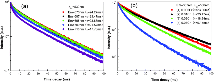
Fig. 10 shows the decay curves of ZnAl2O4: xCr3+ nanofibers calcined at 1200 °C for 5 h. For decay measurement of different emission lines, calcined ZnAl2O4: 0.01Cr3+ nanofibers with optimal emission property are chosen as the representative sample. The decay curves of different emission lines at 676 nm, 687 nm, 698 nm, 709 nm and 718 nm are illustrated in Fig. 10(a), which are almost pure exponential decay. By the single-exponential-fit, the lifetime of R-line is ∼23.47 ms, which is a characteristic decay of phosphorescence. The emission line at 676 nm and 698 nm is about 24.27 ms and 23.86 ms, respectively, which is identical to that of the R-line. For the emission line at 709 nm and 718 nm, which is close to the emission band at 725–775 nm, the lifetime is about 21.57 ms and 17.75 ms, respectively. The similar decay characteristics of the emission lines confirm that the emission lines at 676 nm, 698 nm, 709 nm and 718 nm are due to the vibrational sidebands of zero-phonon R-line. Fig. 10(b) shows the decay curves of the R-line from ZnAl2O4: xCr3+ nanofibers with different Cr doped concentrations. It can be found that a slight deviation occurs in decay curves with the increase of Cr content. Using an approximate single-exponential-fit, the lifetime of the R-line is 23.36 ms, 23.47 ms, 18.84 ms and 9.14 ms for x = 0.005, 0.01, 0.02 and 0.03, respectively, which gradually decreases with the increase of Cr content.
 | ||
| Fig. 10 (a) PL decay curves of ZnAl2O4: 0.01Cr3+ electrospun nanofibers calcined at 1200 °C for 5 h. The excitation wavelength is fixed as 530 nm, while the monitored emission wavelength is 676 nm, 687 nm, 698 nm, 709 nm and 718 nm, respectively. (b) PL decay curves of ZnAl2O4: xCr3+ electrospun nanofibers calcined at 1200 °C for 5 h. The excitation and monitored emission wavelength is fixed as 530 nm and 687 nm, respectively. (1) x = 0.005, (2) x = 0.01, (3) x = 0.02, (4) x = 0.03. | ||
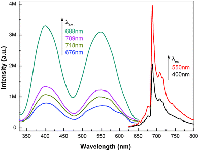 | ||
| Fig. 11 PL excitation and emission spectra of MgAl2O4: 0.02Cr3+ electrospun nanofibers calcined at 1200 °C for 5 h. The excitation wavelength in the emission spectra is 400 nm and 550 nm, while the monitored wavelength in the excitation spectra is 676 nm, 688 nm, 709 nm and 718 nm, respectively. | ||
Fig. 12 illustrates the excitation and emission spectra of calcined MgAl2O4: xCr3+ nanofibers with different Cr doping concentrations. For the emission spectra with a 550 nm excitation, the emission band at 725–800 nm increases monotonously with the increase of Cr content, which is similar with the emission spectra of ZnAl2O4: xCr3+ nanofibers in Fig. 9(a). For the excitation spectra monitoring the R-line at 688 nm, the ratio of the excitation band intensity of 550 nm to 400 nm slightly increases with the increase of Cr content. From the excitation and emission spectra of MgAl2O4: xCr3+ nanofibers in Fig. 12, it can be deduced that the optimal doped concentration of Cr is x = 0.02 in MgAl2O4: xCr3+ electrospun nanofibers.
 | ||
| Fig. 12 PL excitation and emission spectra of MgAl2O4: xCr3+ electrospun nanofibers calcined at 1200 °C for 5 h. The excitation wavelength in the emission spectra is fixed at 550 nm, while the monitored wavelength in the excitation spectra is fixed as 688 nm. (1) x = 0.01, (2) x = 0.02, (3) x = 0.03. | ||
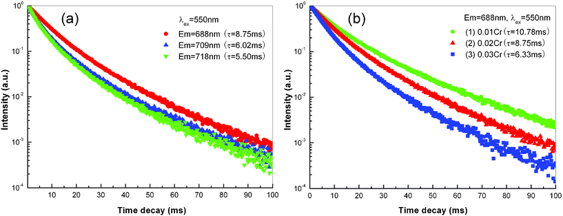
The decay curves of MgAl2O4: xCr3+ electrospun nanofibers are shown in Fig. 13. Choosing MgAl2O4: 0.02Cr3+ nanofibers as a representative sample, the decay curves of different emission lines are illustrated in Fig. 13(a). It can be found that the decay characteristic is different from those of ZnAl2O4: 0.01Cr3+ nanofibers, and a slight deviation occurs in decay curves. If we use a single-exponential-fit to evaluate the lifetime of emission lines, the lifetime of 688 nm, 709 nm and 718 nm emission lines is about 8.75 ms, 6.02 ms and 5.50 ms, respectively. The lifetime of Cr3+ doped MgAl2O4 nanofibers is much shorter than that in ZnAl2O4 nanofibers. From the R-line to low energy emission lines, the lifetime decreases gradually, which is similar with that of ZnAl2O4: xCr3+ nanofibers in Fig. 10(a). Under a 550 nm excitation, the decay curves of R-line in MgAl2O4: xCr3+ nanofibers with different Cr doped concentration is also illustrated in Fig. 13(b). The decay curves also slightly deviate from single-exponential process. By using single-exponential-fit, the lifetime of R-line decreases from 10.78 ms to 8.75 ms and 6.33 ms when the Cr doped concentration increases from 0.01 to 0.02 and 0.03.
 | ||
| Fig. 13 (a) PL decay curves of MgAl2O4: 0.02Cr3+ electrospun nanofibers calcined at 1200 °C for 5 h. The excitation wavelength is fixed at 550 nm, while the monitored emission wavelength is 688 nm, 709 nm and 718 nm, respectively. (b) PL decay curves of MgAl2O4: xCr3+ electrospun nanofibers calcined at 1200 °C for 5 h. The excitation and monitored emission wavelength is fixed at 550 nm and 688 nm, respectively. (1) x = 0.01, (2) x = 0.02, (3) x = 0.03. | ||
3.3 Discussion
It is known that luminescence properties of Cr3+ ions depend strongly on their coordination, crystal field, lattice imperfections, etc. From the Tanabe–Sugano diagram, it can be deduced that the lowest excited state (2Eg or 4T2g) depends mainly on the crystal field strength, Dq/B.46 When Cr3+ ions lie at sites with strong or intermediate crystal field, i.e. Dq/B ≥ 2.3, the lowest excited state is the 2Eg level, which will be responsible for the narrow band phosphorescence with a characteristic lifetime of tens of ms. In the case where Cr3+ ions lie at sites with weak crystal field, i.e. Dq/B < 2.3, the lowest excited state will be the 4T2g level, which will be responsible for the broad band fluorescence with a characteristic lifetime of tens of μs. Therefore, before discussing the noticeable difference between the luminescence properties of ZnAl2O4: xCr3+ and MgAl2O4: xCr3+ nanofibers, it should elucidate the crystal structure of spinel.The so-called normal spinel is described by AB2O4, where A denotes divalent anion, such as Zn2+, Mg2+, etc. B denotes trivalent anion, such as Al3+, Ga3+, etc. As the crystal structure in Fig. 14(a), the spinel structure is a FCC phase with a space group of Fd-3m. In the normal spinel host lattice, A2+ (Zn2+, Mg2+, etc.) ions occupy tetrahedral sites (Td symmetry) and B3+ (Al3+, Ga3+, etc.) ions occupy octahedral sites (D3d symmetry), as shown in Fig. 14(b) and (c), respectively.47 When trivalent Cr3+ ions are doped into a spinel host, due to the 3d3 electron configuration of Cr3+ ions, the crystal field stabilization energy of Cr3+ ions in octahedral sites is almost three times greater than in tetrahedral sites. So Cr3+ ions lie preferentially in octahedral sites to replace B3+ (Al3+, Ga3+, etc.) ions.44
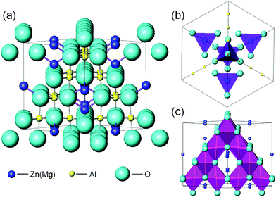 | ||
| Fig. 14 (a) The crystal structure schematic diagram of ZnAl2O4 (MgAl2O4) spinel. (b) Tetrahedral sites occupied by Zn2+ or Mg2+ ions (purple tetrahedral). (c) Octahedral sites occupied by Al3+ ions (pink octahedral). | ||
From the XRD results in Fig. 1 and Fig. 4 and the crystallographic ICSD data, the lattice constants and bond length can be estimated as follows. For the ZnAl2O4: 0.01Cr3+ nanofibers calcined at 1200 °C for 5 h, the lattice constants are a = b = c = 8.088 Å, while the bond length (R) of Mg–O bond and Al–O bond is about 1.967 Å and 1.906 Å, respectively (data from ICSD #94156). For the MgAl2O4: 0.01Cr3+ nanofibers calcined at 1200 °C for 5 h, the lattice constants are a = b = c = 8.114 Å, while the bond length (R) of Mg–O bond and Al–O bond is about 1.933 Å and 1.932 Å, respectively (Data from ICSD #31376). From previous work,48,49 it is known that crystal field strength, Dq is inversely proportional to the quintic of the bond length, R:
| Dq∝1/R5 | (1) |
The shorter bond length means a stronger crystal field strength. Because Cr3+ ions occupy the octahedral sites of Al3+ ions, the bond length of Al–O bond can be utilized to estimate the crystal field strength around Cr3+ ions. Due to the bond length of Al–O bond in MgAl2O4: 0.01Cr3+ being larger than in ZnAl2O4: 0.01Cr3+ nanofibers, it can be deduced that the crystal field strength around Cr3+ ions in MgAl2O4: 0.01Cr3+ is weaker than that in ZnAl2O4: 0.01Cr3+ nanofibers. The relatively precise crystal field strength parameters can be estimated by spectroscopic data as follows:50,51
| 10Dq = ν2 | (2) |
| B = (ν12 + 2ν22 − 3ν1ν2)/(15ν1−27ν2) | (3) |
000 cm−1 and ν2 = 18868 cm−1, then Dq and B are estimated to be 1887 cm−1 and 581 cm−1, respectively. While for MgAl2O4: xCr3+ nanofibers, ν1 = 25000 cm−1 and ν2 = 18182 cm−1, then Dq and B is estimated to be 1818 cm−1 and 668 cm−1, respectively. Therefore, the crystal field strength parameter of Dq/B is calculated to be 3.25 and 2.72 for ZnAl2O4: xCr3+ and MgAl2O4: xCr3+ nanofibers, respectively.
Based on the calculation of crystal field strength above, the PL excitation, emission and decay properties will be discussed successively in the following text.
When Cr3+ ions occupy the octahedral sites, the influence of the octahedral crystal field will split the ground term 4F into the ground level 4A2g and two excited levels 4T1g and 4T2g. The ground level and the first excited level result from t32g configuration, while the second excited level 4T2g is a t22geg configuration. Because the eg orbital is along the octahedral axis, the excited level 4T2g depends strongly on the crystal field strength. Therefore, compared with the excitation spectra of ZnAl2O4: xCr3+ nanofibers, the excitation band of 4A2g→4T2g transition shifts from 530 nm to 550 nm for MgAl2O4: xCr3+ nanofibers due to the weaker crystal field strength.
It is known that a large number of Cr3+ sites exist in the spinel host. When the ZnAl2O4: xCr3+ and MgAl2O4: xCr3+ nanofibers are excited by 4A2g→4T1g and 4A2g→4T2g transitions, the emission lines at 675–725 nm in the PL emission spectra are due to the emission of Cr3+ ions lying at strong crystal field strength sites, while the emission band at 725–800 nm is due to the emission of Cr3+ ions lying at weak crystal field strength sites.52 Due to the smaller crystal field strength, Dq/B for MgAl2O4: xCr3+ nanofibers, which is close to the critical value (Dq/B = 2.3), it can be deduced that Cr3+ ions lying at weak crystal field in MgAl2O4: xCr3+ nanofibers are more than those in ZnAl2O4: xCr3+ nanofibers. This will result in an optimal doping concentration of Cr3+ ions as the R-line emission in MgAl2O4: xCr3+ nanofibers (x = 0.02) is larger than ZnAl2O4: xCr3+ nanofibers (x = 0.01). The crystal field around Cr3+ ions in MgAl2O4: xCr3+ nanofibers is almost a continuous distribution, which can be confirmed by the broadening of emission lines and the increase of background in emission spectra of MgAl2O4: xCr3+ nanofibers. With the increase of Cr doped concentration in spinel nanofibers, the lattice disorder of the spinel host will increase. More Cr3+ ions will occupy the distorted octahedral sites with weak crystal field, which will result in the monotonous increase of the emission band at 725–800 nm with the addition of Cr3+ concentration.
As shown in Fig. 10(a) and Fig. 13(a), due to the contribution from 725–800 nm the emission of Cr3+ ions at weak crystal field increases from 676 nm to 718 nm, the lifetime of emission lines from 676 nm to 718 nm slightly shortens, especially for the emission at longer wavelengths. Compared with the decay curves of ZnAl2O4: xCr3+ nanofibers, the lifetime of Cr3+ ions is much shorter and the decay curves deviate from a single-exponential process in MgAl2O4: xCr3+ nanofibers. It is also due to the larger contribution from the emission of Cr3+ ions at weak crystal field, which results in a double phosphorescence and fluorescence behavior in MgAl2O4: xCr3+ nanofibers. When the concentration of Cr3+ ions in spinel nanofibers increase, due to a large number of Cr3+ ions occupying the weak crystal field sites, the proportion of Cr3+ ions with fluorescence behavior increases. Therefore, with the increase of Cr concentration in spinel nanofibers, the lifetime shortens remarkably and the deviation from single-exponential process becomes more clear.
4. Conclusion
By using a single-nozzle electrospinning technique, ZnAl2O4: xCr3+ and MgAl2O4: xCr3+ hollow nanofibers were synthesized after calcination in air. SEM and TEM results indicate that the calcined nanofibers are hollow microstructures consisting of single layer crystal grains. A ‘gas-push’ model is proposed to elucidate the formation mechanism of hollow nanofibers. Under an excitation at 430 nm or 530 nm for ZnAl2O4: xCr3+ nanofibers, a sharp R-line emission at 687 nm with several vibrational sidebands appears. For MgAl2O4: xCr3+ nanofibers, the broadening of emission lines and the increase of background is observed. The lifetime of Cr3+ ions in ZnAl2O4 nanofibers is about 10–25 ms, while it is about 5–10 ms of MgAl2O4: xCr3+ nanofibers. And in both spinel nanofibers, the lifetime becomes shorter when the monitored emission peak shifts to longer wavelength. Based on the energy of 4A2g→4T1g and 4A2g→4T2g transitions of Cr3+ ions, the crystal field strength parameter, Dq/B is estimated to be 3.25 and 2.72 for ZnAl2O4: xCr3+ and MgAl2O4: xCr3+ nanofibers, respectively. The difference of Dq/B value gives a good explanation of the spectroscopic and decay evolution between ZnAl2O4: xCr3+ and MgAl2O4: xCr3+ nanofibers. The spinel hollow nanofibers with high efficiency and tunable bandwidth luminescence are expected to be applied as waveguides, sensors, displays and lighting in micro/nano-devices.Acknowledgements
This work was financially supported by the Natural Science Foundation of Guangdong Province (1045106410104887), Fundamental Research Funds for the Central Universities (2011ZB0001, 2011ZZ0001, 2011ZP0002), National Natural Science Foundation of China (51102096, 51072060, 50872123), Open research fund of State Key Laboratory of Precision Spectroscopy, and CAS Key Laboratory of Renewable Energy and Gas Hydrate (No.KLREGHy007k6), China Postdoctoral Science Special Foundation (201104350), and UIRT of Guangdong Province.References
- Y. Nakayama, P. J. Pauzauskie, A. Radenovic, R. M. Onorato, R. J. Saykally, J. Liphardt and P. D. Yang, Nature, 2007, 447, 1098 CrossRef CAS.
- F. Wang, Y. Han, C. S. Lim, Y. H. Lu, J. Wang, J. Xu, H. Y. Chen, C. Zhang, M. H. Hong and X. G. Liu, Nature, 2010, 463, 1061 CrossRef CAS.
- Z. H. Nie, A. Petukhova and E. Kumacheva, Nat. Nanotechnol., 2010, 5, 15 CrossRef CAS.
- F. Zhang, Y. Wang, T. Yu, F. Q. Zhang, Y. F. Shi, S. H. Xie, Y. G. Li, L. Xu, B. Tu and D. Y. Zhao, Angew. Chem., Int. Ed., 2007, 46, 7976 CrossRef CAS.
- C. L. Yan, A. Dadvand, F. Rosei and D. F. Perepichka, J. Am. Chem. Soc., 2010, 132, 8868 CrossRef CAS.
- D. Q. Chen, Y. L. Yu, F. Huang, P. Huang, A. P. Yang and Y. S. Wang, J. Am. Chem. Soc., 2010, 132, 9976 CrossRef CAS.
- Y. S. Liu, D. T. Tu, H. M. Zhu, R. F. Li, W. Q. Luo and X. Y. Chen, Adv. Mater., 2010, 22, 3266 CrossRef CAS.
- J. Liu and Y. D. Li, Adv. Mater., 2007, 19, 1118 CrossRef CAS.
- C. L. Yan, L. Nikolova, A. Dadvand, C. Harnagea, A. Sarkissian, D. F. Perepichka, D. F. Xue and F. Rosei, Adv. Mater., 2010, 22, 1741 CrossRef CAS.
- J. Wu and J. L. Coffer, Chem. Mater., 2007, 19, 6266 CrossRef CAS.
- H. W. Song, H. Q. Yu, G. H. Pan, X. Bai, B. Dong, X. T. Zhang and S. K. Hark, Chem. Mater., 2008, 20, 4762 CrossRef CAS.
- Z. Y. Hou, C. X. Li, J. Yang, H. Z. Lian, P. P. Yang, R. T. Chai, Z. Y. Chen and J. Lin, J. Mater. Chem., 2009, 19, 2737 RSC.
- Z. Y. Hou, P. P. Yang, C. X. Li, L. L. Wang, H. Z. Lian, Z. W. Quan and J. Lin, Chem. Mater., 2008, 20, 6686 CrossRef CAS.
- G. P. Dong, X. D. Xiao, Y. Z. Chi, B. Qian, X. F. Liu, Z. J. Ma, E. Wu, H. P. Zeng, D. P. Chen and J. R. Qiu, J. Mater. Chem., 2010, 20, 1587 RSC.
- K. Izumi, S. Miyazaki, S. Yoshida, T. Mizokawa and E. Hanamura, Phys. Rev. B, 2007, 76, 075111 CrossRef.
- A. Jouini, A. Yoshikawa, A. Brenier, T. Fukuda and G. Boulon, Phys. Status Solidi C, 2007, 4, 1380 CrossRef CAS.
- K. Y. Jung, H. W. Lee and H. K. Jung, Chem. Mater., 2006, 18, 2249 CrossRef CAS.
- H. Matsui, C. N. Xu and H. Tateyama, Appl. Phys. Lett., 2001, 78, 1068 CrossRef CAS.
- S. Kück, Appl. Phys. B, 2001, 72, 515 CrossRef.
- W. Z. Yan, F. Liu, Y. Y. Lu, X. J. Wang, M. Yin and Z. W. Pan, Opt. Express, 2010, 18, 20215 CrossRef CAS.
- F. D. Benedetto, A. Camposeo, S. Pagliara, E. Mele, L. Persano, R. Stabile, R. Cingolani and D. Pisignano, Nat. Nanotechnol., 2008, 3, 614 CrossRef.
- Y. Xiao, C. Meng, P. Wang, Y. Ye, H. K. Yu, S. S. Wang, F. X. Gu, L. Dai and L. M. Tong, Nano Lett., 2011, 11, 1122 CrossRef CAS.
- H. Wu, Y. Sun, D. D. Lin, R. Zhang, C. Zhang and W. Pan, Adv. Mater., 2009, 21, 227 CrossRef CAS.
- J. M. Moran-Mirabal, J. D. Slinker, J. A. DeFranco, S. S. Verbridge, R. Ilic, S. Flores-Torres, H. Abruna, G. G. Malliaras and H. G. Craighead, Nano Lett., 2007, 7, 458 CrossRef CAS.
- G. P. Dong, X. D. Xiao, Y. Z. Chi, B. Qian, X. F. Liu, Z. J. Ma, S. Ye, E. Wu, H. P. Zeng, D. P. Chen and J. R. Qiu, J. Phys. Chem. C, 2009, 113, 9595 CAS.
- X. F. Duan, Y. Huang, R. Agarwal and C. M. Lieber, Nature, 2003, 421, 241 CrossRef CAS.
- A. I. Hochbaum and P. D. Yang, Chem. Rev., 2010, 110, 527 CrossRef CAS.
- Z. R. Tang, Y. H. Zhang and Y. J. Xu, RSC Adv., 2011, 1, 1772 RSC.
- M. L. Chen, M. D. Dong, R. Havelund, V. R. Regina, R. L. Meyer, F. Besenbacher and P. Kingshott, Chem. Mater., 2010, 22, 4214 CrossRef CAS.
- M. L. Chen and F. Besenbacher, ACS Nano, 2011, 5, 1549 CrossRef CAS.
- J. Song, M. L. Chen, M. Buster Olesen, C. X. Wang, R. Havelund, Q. Li, E. Q. Xie, R. Yang, P. Bøggild, C. Wang, F. Besenbacher and M. D. Dong, Nanoscale, 2011, 3, 4966 RSC.
- X. F. Lu, C. Wang and Y. Wei, Small, 2009, 5, 2349 CrossRef CAS.
- A. Greiner and J. H. Wendorff, Angew. Chem., Int. Ed., 2007, 46, 5670 CrossRef CAS.
- D. Li and Y. N. Xia, Adv. Mater., 2004, 16, 1151 CrossRef CAS.
- D. Li and Y. N. Xia, Nano Lett., 2004, 4, 933 CrossRef CAS.
- M. Bognitzki, W. Czado, T. Frese, A. Schaper, M. Hellwig, M. Steinhart, A. Greiner and J. H. Wendorff, Adv. Mater., 2001, 13, 70 CrossRef CAS.
- S. Koombhongse, W. X. Liu and D. H. Reneker, J. Polym. Sci., Part B: Polym. Phys., 2001, 39, 2598 CrossRef CAS.
- W. Li, C. Y. Cao, C. Q. Chen, Y. Zhao, W. G. Song and L. Jiang, Chem. Commun., 2011, 47, 3619 RSC.
- T. Y. Zhao, Z. Y. Liu, K. Nakata, S. Nishimoto, T. Murakami, Y. Zhao, L. Jiang and A. Fujishima, J. Mater. Chem., 2010, 20, 5095 RSC.
- J. C. Di, H. Y. Chen, X. F. Wang, Y. Zhao, L. Jiang, J. H. Yu and R. R. Xu, Chem. Mater., 2008, 20, 3543 CrossRef CAS.
- D. Li, J. T. McCann and Y. N. Xia, Small, 2005, 1, 83 CrossRef CAS.
- G. P. Dong, X. D. Xiao, L. L. Zhang, Z. J. Ma, X. Bao, M. Y. Peng, Q. Y. Zhang and J. R. Qiu, J. Mater. Chem., 2011, 21, 2194 RSC.
- G. P. Dong, X. F. Liu, X. D. Xiao, B. Qian, J. Ruan, S. Ye, H. C. Yang, D. P. Chen and J. R. Qiu, Nanotechnology, 2009, 20, 055707 CrossRef.
- P. J. Deren, M. Malinowski and W. Strqk, J. Lumin., 1996, 68, 91 CrossRef CAS.
- V. C. Costa, F. S. Lameiras, M. V. B. Pinheiro, D. F. Sousa, L. A. O. Nunes, Y. R. Shen and K. L. Bray, J. Non-Cryst. Solids, 2000, 273, 209 CrossRef CAS.
- S. Sugano, Y. Tanabe and H. Kamimura, Multiplets of Transition-Metal Ions in Crystals, Academic Press, New York, 1970 Search PubMed.
- S. B. Berger, J. Appl. Phys., 1965, 36, 1048 CrossRef CAS.
- B. Henderson and G. G. Imbush, Optical Spectroscopy of Inorganic Solids, Clarendon, Oxford, 1989.
- S. Ye, Z. S. Liu, X. T. Wang, J. G. Wang, L. X. Wang and X. P. Jing, J. Lumin., 2009, 129, 50 CrossRef CAS.
- V. Singh, R. P. S. Chakradhar, J. L. Rao and D. K. Kim, J. Lumin., 2009, 129, 130 CrossRef CAS.
- W. W. Zhang, J. Y. Zhang, Z. Y. Chen, T. M. Wang and S. K. Zheng, J. Lumin., 2010, 130, 1738 CrossRef CAS.
- K. E. Lipinska-Kalita, P. E. Kalita, D. M. Krol, R. J. Hemley, C. L. Gobin and Y. Ohki, J. Non-Cryst. Solids, 2006, 352, 524 CrossRef CAS.
| This journal is © The Royal Society of Chemistry 2012 |