A facile method to prepare zirconia electrospun fibers with different morphologies and their novel composites based on cyanate ester resin
Dake
Qin
,
Aijuan
Gu
*,
Guozheng
Liang
* and
Li
Yuan
Jiangsu Key Laboratory of Advanced Functional Polymer Design and Application, College of Chemistry, Chemical Engineering and Materials Science, Soochow University, Suzhou, 215123, China
First published on 15th December 2011
Abstract
Using zirconium propoxide as the precursor, a new method combining the advantages of electrospinning and sol–gel approaches is set up to facilely fabricate zirconia (ZrO2) nanofibers with controllable chemical and morphological structures in batch size on a standard electrospinning equipment. Interestingly, zirconia (ZrO2) nanofibers with different morphologies were prepared, the influence of the preparing parameters on the structure of the ZrO2 nanofibers were investigated. Results show that by adjusting the preparing parameter, the ZrO2 nanofibers can be porous or compact fibers, in addition the crystalline structure, and dimensions of pores can be also changed. Based on the successful preparation of these ZrO2 electrospun fibers, novel composites consisting of ZrO2 electrospun fibers and cyanate ester (CE) resin were developed, which show significantly reduced curing temperature compared to CE owing to the presence of hydroxyl groups on the fibers. The dynamic mechanical and dielectric properties of ZrO2/CE composites are closely related to the morphological structure of ZrO2 fibers because the latter determines the chemical structure and crosslinking density of the matrix as well as the interfacial adhesion of the corresponding composites. These interesting results demonstrate that the method proposed herein provide a new approach to design and prepare ceramic nanofibers and corresponding composites with controlled structure and expected performance for cutting-edge industries.
1 Introduction
Traditionally, materials are divided into three kinds, of which polymer and ceramic belongs to two sorts, each of them has unique properties, and thus shows special applications.1,2 However, with the rapid development of modern industries, an individual polymer or ceramic is found to be difficult to meet the requirements of cutting-edge fields, hence ceramic/polymer composites have been received increasing attentions because they not only combine the advantages of both polymer and ceramic, and may have new unique properties which are not possessed by either polymers or ceramics.3,4There are two methods to prepare ceramic/polymer composites, one is dispersing inorganic fillers into a polymeric matrix by surface modification and/or thorough stirring to form 0–3 type composites,5,6 and the other is using long fibers.7 The results of many researches presented in literature show that to get a complete and uniform dispersion of fillers (especially nanofillers) in polymer matrix is still a difficult and challenge topic today;8,9 while the preparation of long ceramic fibers is usually not easy and expensive. Therefore, it is of great interesting to develop new methods to prepare novel ceramic/polymer composites.
Nanocomposites based on non-woven mats maybe a good choice to solve above problems because non-woven mats show the advantages of both nano-materials and long fibers. Electrospinning has been considered as the simplest and versatile nanotechnology for preparing nanofibers and non-woven mats. Many non-woven mats based on nanofibers have been successfully fabricated by electrospinning.10–12 However, few articles focused on preparing electrospinning fiber/polymer composites.
On the other hand, it is well known that the interfacial nature plays a crucial influence on the performance of composites,13,14 hence many methods have been developed to achieve desirable interfacial adhesion. For a long time, the chemical technique has been widely employed to improve the interfacial nature between different phases of a composite.15 However, the physical method is attracting increasing attention of researchers worldwide recently because it may overcome the drawback of chemical methods, and thus provides the greatest possibility for maintaining the outstanding properties of the original fillers/fibers.16,17 Increasing the surface roughness of fibers is the typical reflection of physical methods,18 however, this is not easy to perform on the nanofibers, so we propose to design and synthesis nanofibers with pores, these pores are expected to be filled by the resin matrix, and thus provide a physical interaction between fibers and the resin matrix, this maybe an easy way to achieve a good physical interface although no literature has reported this so far.
Principles of composites point out that the properties of ceramic/polymer composites are greatly dependent on the nature of the ceramic and polymer, so they should be carefully selected. Zirconia (ZrO2) is an important category of advanced ceramic which has been widely studied because of unique properties such as high toughness and chemical stability, good refractory properties and ionic conductivity.19 Many efforts have been devoted to the synthesis and application of ZrO2 fibers by electrospinning,20–27 however they used zirconyl chloride or zirconia as the precursor, this approach has some obvious drawbacks. The hydrolysis speed of either zirconyl chloride or zirconia is not rapid enough, hence the whole hydrolysis process will continue even after the electrospinning solution is ejected from the electrospinning setup orifice to form nanofibers on the collection set. That is to say, the hydrolysis will proceed continuously, and then makes the nanofibers formed initially to conglutinate together and partially lose their fibrous morphology during the continuous hydrolysis and condensation of the precursor nanofibers.28 Hence the morphology of the resultant nanofibers is not easy to control; moreover, the production of zirconia electrospun fibers in batch size is not possible. Therefore, developing a new method to overcome the above disadvantages for facile preparation of ZrO2 nanofibers is one target of our work presented herein.
With regard to polymeric matrix, thermosetting resins exhibit unique advantages on the processing characteristics over thermoplastics.30,31Cyanate ester (CE) resin offers advantages as the composite matrix owing to its outstanding thermal stability, excellent dielectric property, high mechanical property, good moisture and radiation resistance; hence it is widely regarded as the right candidate with the great potential to prepare structural/functional materials of this century.32,33 However, unfortunately, no literature discusses the preparation and characterization of ZrO2/CE composites.
In this paper, a new method is set up to facilely fabricate zirconia (ZrO2) nanofibers with controllable chemical and morphological structures in batch size on a standard electrospinning equipment, which employs zirconium propoxide as the precursor, and combines the advantages of electrospinning and sol–gel approaches. Based on this development, zirconia (ZrO2) nanofibers with different morphologies were prepared, the influence of the preparing parameters on the structure of the ZrO2 nanofibers was investigated; in addition, novel composites based on CE resin and non-woven mats of ZrO2 nanofibers with different structure were prepared, and the influences of the surface nature and morphologies of ZrO2 nanofibers on the typical properties of composites were systematically studied. The aim of this paper is developing a facile method to prepare ZrO2 nanofibers with controlled structure, and corresponding composites with desirable high performance for cutting-edge industries.
2. Experimental
2.1 Materials
2,2′-Bis(4-cyanatophenyl)isopropylidene (CE) was bought from Zhejiang Shangyu Chemical Ltd., China. Zirconium propoxide (Zr(OCH2CH2CH3)4), polyvinylpyrrolidone (PVP, Mw≈1300000), acetic acid, and ethanol were all commercial reagents with analytic grades, and used as received.2.2 Preparation of electrospinning solution
In a typical procedure, 0.6 g PVP was mixed with 2.0 mL of acetic acid and 10.0 mL of ethanol in a glove box to form a solution. After 30 min, 6.0 mL zirconium propoxide was added to the solution, followed by magnetic stirring for 2 h to get the electrospinning solution.2.3 Preparation of ZrO2 fibers and performs
The electrospinning solution was subsequently electrospun using a standard electrospinning equipment at a feeding rate of 9.0 mL h−1 through a needle with a diameter of 1.23 mm. The accelerating voltage was 23.50 kV. The distance between the needle tip and the collector (a piece of flat aluminum foil) was 15 cm. The obtained as-spun fibers form non-woven mats, which were cut out into sheets with the suitable dimensions, and then piled up together to form a fiber congeries. The fiber congeries was subsequently dried at 60 °C for 12 h before calcination.The fiber congeries was put into a calcinator at a preset calcination temperature for 2 h (the heating rate from room temperature to the calcination temperature is 10 °C min−1), and then naturally cooled overnight in the calcinator to form a fiber preform. The resultant fiber preform is coded as ZrO2(n), where n represents the calcination temperature, n is 600, 800, 1000, and 1200.
2.4 Preparation of ZrO2/CE composites
Appropriate quantities of CE were heated to 150 °C and maintained at that temperature with stirring till a clear liquid was obtained.ZrO2(n) fiber preform was filled into the mould, and then heated to 150 °C. After that the melting CE was immediately cast into the mould, followed by degassing under vacuum at 150 °C for 10 min. The mold was then put into an oven for curing and postcuring taking the programmed procedures of 150 °C/2 h + 180 °C/2 h + 200 °C/2 h + 220 °C/2 h, and 240 °C/4 h, successively. The resultant composite was coded as ZrO2(n)/CE.
The content of fibers can be calculated by the weights of the composite before and after calcination at 1200 °C for 2 h, which varies from 10.47 to 11.68 wt%, indicating that all composites prepared herein have the similar content of fibers, and thus the influence of the content of fibers on the properties of composites can be ignored.
2.5 Characterization
Field Emission Scanning Electron Microscopy (FESEM) (S4800, HITACHI Company, Japan) coupled with energy disperse X-ray spectrometer (EDS) was employed to observe the morphology of samples. All samples should be dried at 100 °C for 6 h, and then coated with gold before tests.Powder X-ray Diffraction (XRD) measurements were performed on an X-ray diffractometer (X'Pert-Pro MPD, PANalytical B.V. Corporation, Netherlands) with Ni–filtered Cu Ka radiation. The XRD spectra were obtained by scanning over a 2θ angle range from 24 to 36° at a scanning speed of 2°/min and a step width of 0.028.
Fourier Transform Infrared (FTIR) spectra were recorded using a Nicolet 5700 FT-IR spectrometer (Thermo Electron Corporation, USA) with KBr for solid samples. The corresponding spectrum of pure KBr was regarded as the background spectrum.
Differential Scanning Calorimeter (DSC) analyses were done using a Diamond DSC (PE Corporation, USA) with a heating rate of 10 °C min−1 in a nitrogen atmosphere.
The thermogravimetric (TG) analysis was inspected in an air atmosphere by a Simultaneous Differential Thermal Analyzer (SDT) (Q600, TA Instruments Company, USA) in the temperature range from 50 to 1200 °C with a heating rate of 10 °C min−1
Dynamic Mechanical Analyses (DMA) were performed on a Q800 DMA (TA Instrument Company, USA) apparatus in a single-cantilever bending mode with a heating rate of 3 °C min−1 and a frequency of 1 Hz.
The dielectric property was tested using a Broadband Dielectric Spectrometer (Novocontrol Concept 80, Germany) at room temperature over the frequency ranged from 1 to 106 Hz. The dimensions of the sample were (10 ± 0.2) × (10 ± 0.2) × (1.5 ± 0.01) mm3.
3. Results and discussion
3.1 Synthesis and characterization of ZrO2 fibers
As stated in the Introduction part, the physical interaction between fibers and the resin matrix is an important sort of interfacial adhesion of composites, so it is interesting to design and synthesize fibers with pores, these pores are expected to be filled by the resin matrix and thus provide a physical interaction between fibers and the resin matrix. However, in the case of ZrO2 fibers, many efforts have been devoted to synthesize electrospun ZrO2 fibers, but some undesirable problems exist as described in the Introduction part. In addition, it is worthy to point out that no ZrO2 fibers with pores have been reported in the literature.In this paper, we develop a new method exhibiting obvious advantages over previous techniques, which utilizes zirconium propoxide as the precursor, and combines the advantages of electrospinning and sol–gel approaches, consequently, the new method can facilely produce ZrO2 electrospun fibers with controllable chemical and morphological structures in batch size on a standard electrospinning equipment. This attractive feature is attributed to the very fast hydrolysis speed of zirconium propoxide by moisture in the air, especially, in the case of the huge contact area between nanofibers and moisture in the air, so continuous networks gels of precursors are able to form once the electrospinning solution is ejected from the electrospinning setup orifice.29 This means that the hydrolysis process will complete before the nanofibers reach the collect set, hence the chemical and morphological structures of nanofibers on the collection set do not change. Therefore, we can facilely produce zirconia electrospun fibers with controllable chemical and morphological structures in batch size using this method.
In order to evaluate the chemistry of ZrO2(n) fibers calcined, the FTIR spectra of PVP and ZrO2(n) fibers calcined at different temperatures were recorded and are shown in Fig. 1. All fibers show similar spectra, but in which no characteristic peaks (1663 cm−1, 1291 cm−1) reflecting PVP can be observed, indicating that organic materials have been removed from the fibers after calcination because PVP and carbon will completely decompose when the temperature is higher than 680 °C as shown in Fig. 2. On the other hand, all fibers exhibit a typical strong and wide peak at 3450 cm−1, and a peak at 1640 cm−1, assigned to the stretching vibration and the bending vibration of hydroxyl groups, respectively,35 indicating that all fibers have hydroxyl groups which will a play important role in the curing behaviour of CE resin based composites as will be discussed later.
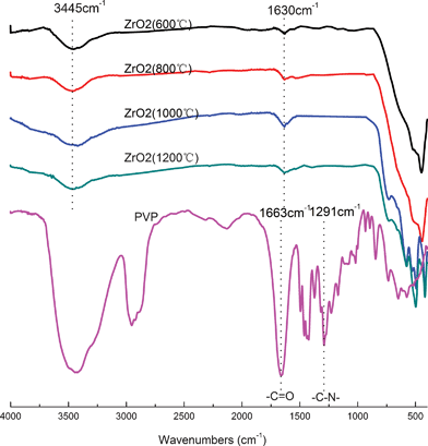 | ||
| Fig. 1 FTIR spectra of PVP and ZrO2 fibers calcined at different temperatures. | ||
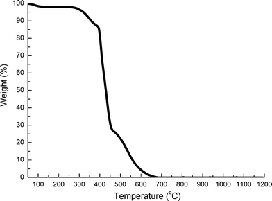 | ||
| Fig. 2 TG curve of PVP in an air atmosphere. | ||
Fig. 3 shows SEM images of as-spun zirconium propoxide/PVP fibers and their calcined products (ZrO2(n) fibers), it can be seen that as-spun zirconium propoxide/PVP fibers have smooth surfaces and uniform distribution (Fig. 3a). After calcination at 600 °C, 800 °C or 1000 °C, the resultant ZrO2(n) fibers have an average diameter of several hundred nanometres; importantly, they have pores but different pore dimensions, specifically, the dimensions of ZrO2(600) and ZrO2(800) fibers are only several nanometres (Fig. 3b–3c), while those of ZrO2(1000) fibers are about tens of nanometres (Fig.3d). However, when the calcination temperature increases to 1200 °C, pores can not be observed on either surfaces or the internal parts of the resultant ZrO2(1200) fibers as shown in Fig. 3e.
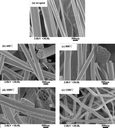 | ||
| Fig. 3 SEM micrographs of electrospinning fibers calcinated at different calcination temperatures | ||
The appearance of pores on the ZrO2 fibers results from the thermal decomposition of PVP in the as-spun nanofibers during calcination. However, when the calcination temperature increases to 1200 °C, sintering will occur, and thus the resultant ZrO2(1200) fibers do not have pores. These interesting results reveal a facile method to synthesize ZrO2 nanofibers with nanometre pores on the interior or surface by a controlled calcination process. Based on the above phenomena, the non-woven mats made of these ZrO2 nanofibers are expected to exhibit two types of pores, that is, the relatively large pores formed through the interconnection of the ceramic nanofibers, and the smaller pores within individual nanofiber.
It is known that ZrO2 has three kinds of crystalline structures, they are tetragonal, monoclinic and cubic phases, so ZrO2 with different crystalline structures will have different performances, and it is interesting to characterize the crystalline structure of ZrO2 fibers synthesized herein. XRD measurements were carried out, and corresponding XRD patterns of ZrO2(n) fibers are plotted in Fig. 4. ZrO2(600) fiber has one sharp peak at 30.2°, which is the characteristic peak of t(111) for tetragonal phase.34 The peak also appears in the XRD curve of ZrO2(800); moreover, two new peaks at 28.2° and 31.5° can also be observed, they are the characteristic peaks of m (![[1 with combining macron]](https://www.rsc.org/images/entities/char_0031_0304.gif) 11) and m(111) for the monoclinic phase, respectively, indicating that ZrO2(800) fiber has both tetragonal and monoclinic crystalline structures. With regard to the XRD curves of ZrO2(1000) and ZrO2(1200) fibers, the intensities of the characteristic peaks of monoclinic phase significantly increase, but that of tetragonal phase greatly decreases, reflecting that the structure of ZrO2(1000) and ZrO2(1200) fibers mainly consist of monoclinic phase with a small amount of tetragonal phase.
11) and m(111) for the monoclinic phase, respectively, indicating that ZrO2(800) fiber has both tetragonal and monoclinic crystalline structures. With regard to the XRD curves of ZrO2(1000) and ZrO2(1200) fibers, the intensities of the characteristic peaks of monoclinic phase significantly increase, but that of tetragonal phase greatly decreases, reflecting that the structure of ZrO2(1000) and ZrO2(1200) fibers mainly consist of monoclinic phase with a small amount of tetragonal phase.
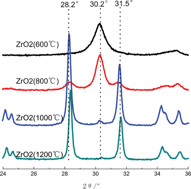 | ||
| Fig. 4 XRD curves of ZrO2 fibers calcined at different temperatures. | ||
The content of monoclinic phase in ZrO2 fibers, coded as Xm, can be calculated by using eqn (1)

| (1) |
![[1 with combining macron]](https://www.rsc.org/images/entities/char_0031_0304.gif) 11) and Im(111) are the intensities of monoclinic peak of ZrO2, and It(111) is the intensity of tetragonal peak of ZrO2.
11) and Im(111) are the intensities of monoclinic peak of ZrO2, and It(111) is the intensity of tetragonal peak of ZrO2.
Because ZrO2(600) only has tetragonal crystalline structure, so its Xm value is 0. In the case of other three ZrO2 fibers, all of them have both tetragonal and monoclinic phases. The Xm values of ZrO2(800), ZrO2(1000) and ZrO2(1200) fibers are 0.26, 0.97 and 0.99, respectively. In other words, with the increase of the calcination temperature from 600 to 1200 °C, the crystalline structure of ZrO2 fibers almost changes from a tetragonal phase to a monoclinic crystalline structure, while the crystalline grain tends to grow up at high temperature. These results are similar to the investigation reported by Erin Davies's group, although the fibers are not porous fibers.21
3.2 Effect of the nature of ZrO2 fibers on the curing behavior and cured structure of composites
For a thermosetting system, its curing behavior determines the structure, and thus the performance of the cured resin, so it is necessary to first investigate the effect of ZrO2 fibers on the curing behavior and that on cured structure of the crosslinked network. Fig. 5 gives the DSC curves of neat CE and uncured ZrO2/CE composites. It can be seen that each sample shows a single exothermal peak, indicating that the addition of ZrO2 fibers does not change the curing mechanism of CE, but the whole peak of either composite appears at obviously lower temperature compared with that of CE. For example, with the addition of ZrO2 fibers to CE resin, the peak curing temperature of the resultant ZrO2(600)/CE, ZrO2(800)/CE, ZrO2(1000)/CE and ZrO2(1200)/CE composites shifts from 312 °C to 290, 274, 285, and 268 °C, respectively, suggesting that ZrO2 fibers significantly accelerate the whole curing process of CE, but the catalyzing degree is closely related to the nature of ZrO2 fibers.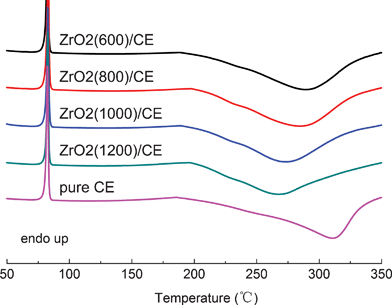 | ||
| Fig. 5 DSC curves of neat CE and uncured ZrO2/CE composites. | ||
As shown in the FTIR spectra of all ZrO2 fibers (Fig.1) all fibers have hydroxyl groups, hence it is reasonable to observe the significantly decreased curing temperature because hydroxyl groups have a remarkable catalytic effect on the cyclotrimerization of –OCN to form crosslinked triazine rings.36 On the other hand, Jung's group found that the concentration of hydroxyl groups on the surface of monoclinic ZrO2 is generally higher than that on tetragonal ZrO2,37 hence it is not surprising to observe that ZrO2 fibers with higher calcination temperature exhibit a bigger catalyzing effect on the curing of CE.
Generally, high curing and postcuring temperature is one of the key disadvantages of thermal resistant resins including CE resin,38 how to overcome this drawback has been an important topic on developing high performance resins and related composites.39,40 Therefore the improved curing behavior of ZrO2/CE is very attractive for applications.
In fact, no reaction takes place if thoroughly purified cyanate esters are heated, however, cyanate esters are very sensitive to the materials surroundings, and thus can be applied for thermal curing. The curing mechanism of CE monomer is to form a triazine ring network by thermal cyclotrimerization, which can be catalyzed by active hydrogen including hydroxyl groups.41 The curing mechanism of CE with the presence of hydroxyl groups is complicated, specifically, the –OCN group of CE can react with hydroxyl group under the heating condition to form the iminocarbonate, a reactive intermediate product, which can further react with more molecules of CE to generate triazine ring.42,43 Note that the hydroxyl group may become the end group of a triazine ring and terminate the further growth of the triazine ring network, hence the whole cured structure of the matrix in ZrO2/CE composite is still the crosslinked network made up of triazine rings, but which contains different parts with different molecular weights rather than a whole homogenous bulk.
3.3 Effect of the structure of ZrO2 fibers on properties of ZrO2/CE composites
Fig. 6 shows the SEM images of the cross-sections for ZrO2/CE composites, it can be seen that ZrO2 fibers are randomly and well dispersed in the CE resin matrix, hence each composite is isotropic. Fig. 7 shows an overlay plots of storage modulus-temperature for cured CE resin and ZrO2/CE composites. All composites exhibit higher storage moduli in glassy state than in the cured CE resin, this result is expected because ZrO2 fibers have a higher rigidity than the CE resin.44 In addition, the presence of inorganic fillers will bring a big restriction on the molecular movement. With regard to composites, it is interesting to find that the composite based on fibers calcined at higher temperature tends to have high storage modulus, however ZrO2(600) fiber does not follow this trend, which does not exhibit the lowest modulus but shows a slightly higher storage modulus than ZrO2(1000)/CE. This phenomenon can be explained from the influence of the structure of ZrO2 fibers on the performance. First, many scholars researched the relationship between crystalline structure and mechanical property of ZrO2, and found that ZrO2 with higher content of tetragonal phase has higher strength, modulus and toughness.45 In the case of ZrO2 fibers synthesized herein, as the calcination temperature increases, the content of tetragonal phase gradually decreases as discussed above, hence the corresponding ZrO2/CE composite is expected to have a gradually increased storage modulus. Second, besides the difference in the crystalline structure, whether there are pores on the internal and (or) surfaces of fibers is another difference among these fibers calcined at different temperatures. Generally, a structure with a bigger compact degree will have a higher modulus, meaning that the addition of ZrO2(1200) to CE resin tends to prepare composite with the highest modulus, while that of ZrO2(600) will lead to the opposite result. Third, TG and EDS analyses (Fig. 1 and 8) show that ZrO2(600) fibers contain carbon, this is attributed to the char yield of PVP during calcinations. The weight loss (4.35%) from 600 °C to 1200 °C is caused by the oxidation of carbon. Because carbon has higher modulus than ZrO2,46 so the existence of residual carbon element on ZrO2(600) fibers will make some contribution to increase the modulus. Obviously, the above two parameters play a combined role on the value of storage modulus, and consequently lead to the experimental results shown in Fig. 7.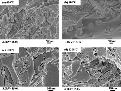 | ||
| Fig. 6 SEM micrographs of the cross-sections for ZrO2/CE composites based on ZrO2 fibers calcined at different temperatures. | ||
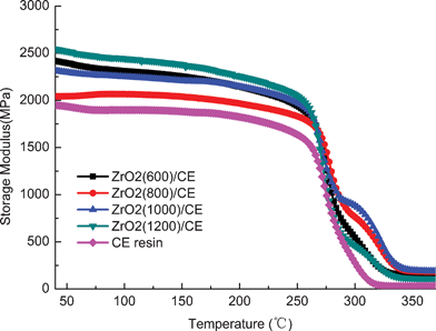 | ||
| Fig. 7 Overlay plots of storage modulus–temperature for cured CE resin and ZrO2/CE composites. | ||
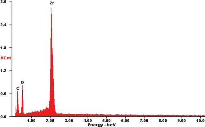 | ||
| Fig. 8 EDS curve of ZrO2(600) fibers. | ||
The effectiveness of fillers on the modulus of the composites can be represented by a coefficient C, which is calculated by using eqn (2):47
 | (2) |
| Sample | Coefficient C | Tg (°C) | Mc (g mol−1) |
|---|---|---|---|
| CE resin | — | 311 | 631.7 |
| ZrO2(600)/CE | 0.2465 | 291, 315 | 126.9 |
| ZrO2(800)/CE | 0.1818 | 300, 326 | 103.5 |
| ZrO2(1000)/CE | 0.1766 | 293, 326 | 102.3 |
| ZrO2(1200)/CE | 0.3564 | 291, 319 | 169.4 |
It is explained that as described above, ZrO2(1000) fibers are porous with tens of nanometres diameter pores, so it is possible for more CE molecules to enter the pores of ZrO2 fibers, triggering a greater physical interaction between the ZrO2 fibers and the CE resin matrix. Comparatively, the smaller dimensions of pores for ZrO2(600) and ZrO2(800) fibers provide smaller physical interaction.
Fig. 9 shows overlay tanδ–temperature curves of cured CE resin and ZrO2/CE composites. Since the tanδ peak occurs in a temperature range over which the polymer changes from a glassy state to an elastic state, hence the peak temperature of which is often taken as the glass transition temperature of a polymer. In addition, the shape of tanδ peak may be used as a convenient indicator of the morphology for multiphase materials.47
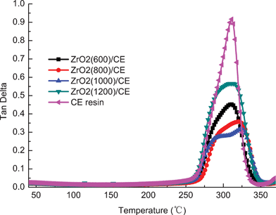 | ||
| Fig. 9 Overlay plots of tanδ versus temperature for cured CE resin and ZrO2/CE composites. | ||
From the view of molecular motion, the intensity of the tanδ peak represents the ability of the molecular motion, and the greater the intensity, the bigger the ability of the molecular movement.48 Compared with the CE resin, the molecules in composites are not easy to move owing to the restriction of ZrO2 fibers and the increased crosslinking density (which will be discussed below), therefore it is reasonable to find that the tanδ peaks of all composites have remarkable lower intensities than that of CE resin.
CE resin has a strong and sharp peak at about 311 °C, indicating that CE resin possess a single-phase structure; while each ZrO2/CE composite exhibits a broad and complex shape of tanδ, which can be divided into two peaks appearing at 315–326 °C and 291–300 °C, respectively, by the Gaussian fitting,49 reflecting that each composite has a multi-phase structure, and thus two Tg values. These results can be explained by the following reasons. First, it is known that CE monomer cures thorough the thermal cyclotrimerization to form triazine ring network. In the case of the ZrO2/CE composites, they contain different parts including a triazine ring network as that of the pure CE resin, but also that terminated by hydroxyl groups as discussed above. Second, ZrO2(600), ZrO2(800) and ZrO2(1000) fibers have pores which will be filled by the resin matrix during the fabrication process of the composites. Obviously, these filled resins have different transition behaviors from those outside the pores because the former is supposed to obtain a bigger restriction resulting from the limited space. Different from the first factor, the second factor can be regarded as a physical interaction. The above two factors are responsible for the broadened and complex tanδ peaks owned by ZrO2/CE composites. Note that ZrO2(1200) fibers do not have pores, meaning that the fibers only have the first parameter, and thus the ZrO2(1200)/CE composite has the highest intensity among the four composites.
The crosslinking density is another important property of a thermosetting resin and related materials, which can be described by Mc, the molecular weight between entanglements or crosslinked sites.41 According to the physical meaning of Mc, it can be seen that Mc value is inversely proportional to the crosslinking density. The Mc value can be calculated by eqn (3):50,51
 | (3) |
The values of Mc calculated from eqn (3) are summarized in Table 1. All composites have a remarkably smaller Mc values than the CE resin, suggesting that the former has a significantly higher crosslinking densities than the latter. This can be explained from chemical and physical crosslinking aspects. As discussion above that –OH can catalyze the cyclotrimation of –OCN groups, meaning that under the same curing and postcuring procedures, the resin matrix in the composites has a bigger crosslinking density than the CE resin. On the other hand, ZrO2(600), ZrO2(800) and ZrO2(1000) fibers have pores which allow much contact of the CE resin with –OH groups on the fibers, and thus increases the formation of hydrogen bonds between the –OH groups of the fibers, oxygen and/or nitrogen atoms of the triazine rings, this physical “crosslinking” also makes contribution to the whole crosslinking density. Because ZrO2(1200) fibers do not have pores, the ZrO2(1200)/CE composite has smaller crosslinking density than the other three composites.
Fig. 10 shows the dependence of dielectric constant (ε') on the frequency for neat CE resin and ZrO2/CE composites over a wide frequency range at room temperature. The dielectric constant and its frequency dependence of ZrO2/CE composites are determined by the structure of the ZrO2 fibers. Specifically, the dielectric constant of ZrO2(600)/CE composite shows obvious dependence on the frequency, this can be ascribed to the existence of carbon on the ZrO2(600) fibers (Fig. 8). It is known that carbon is an electric conductor, which can easily induce space polarization owing to the charge accumulation at the interfaces, and affect the dielectric behavior as the frequency changes.46,52
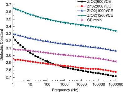 | ||
| Fig. 10 Frequency dependence of dielectric constant of cured CE resin and ZrO2/CE. | ||
The above phenomenon does not appear for the ZrO2(800)/CE, ZrO2(1000)/CE and ZrO2(1200)/CE composites, in opposite, they show similar and excellent stability of dielectric constant on frequency as the CE resin. Because ZrO2 has big dielectric constant (∼23),53 hence it is not a surprise to find that the ZrO2/CE composites have higher dielectric constant than CE resin. However, it is interesting to note that the experimental values of dielectric constant for all ZrO2/CE composites are smaller than their corresponding theoretical values calculated by the common “Rule of Mixture” (Table 2). Because the “Rule of Mixture” proposes that there is no interaction between two components,54 obviously, this does not fit with the situation of ZrO2/CE composites as discussed above. In fact, this phenomenon also confirms that there is a good interaction between ZrO2 and CE resin. On the other hand, the pores of fibers contain air, of which the dielectric constant is as low as 1.0, hence the presence of air would reduce the dielectric constant of ZrO2/CE composites. There is no pore in the ZrO2(1200) fibers, so the dielectric constant of ZrO2(1200)/CE composite is relatively close to the theoretical value.
| Sample | Dielectric constant (at 1 kHz) | |
|---|---|---|
| Theoretical | Experimental | |
| CE resin | — | 3.01 |
| ZrO2(600)/CE | 3.67 | 2.84 |
| ZrO2(800)/CE | 3.68 | 2.86 |
| ZrO2(1000)/CE | 3.75 | 3.16 |
| ZrO2(1200)/CE | 3.71 | 3.46 |
| ZrO2 fibers | — | 23 |
4. Conclusions
A new facile method is set up to fabricate zirconia (ZrO2) nanofibers with controllably chemical and morphological structures in batch size on a standard electrospinning equipment, which employs zirconium propoxide as the precursor, and combines the advantages of electrospinning and sol–gel approaches.By adjusting the calcination temperature from 600 to 1200 °C, ZrO2 nanofibers with different morphologies can be facilely prepared, the different morphologies mainly include the existence of pores or not, the dimensions of the pores, and the crystalline structure. Although all ZrO2 fibers have a significant catalytic effect on the curing of CE, the catalyzing effect is related to the structure of ZrO2 fibers, so does the cured structure of the crosslinked network; in addition, the composites show different physically interfacial adhesion and macro-performance. Compared with neat CE resin, ZrO2/CE composites have higher glassy and rubbery storage moduli, bigger crosslinking densities. The experimental values of dielectric constant for all ZrO2/CE composites are smaller than their corresponding theoretical values calculated by the common “Rule of Mixture” owing to the good physical interaction between ZrO2 and CE resin. These interesting results demonstrate that the method proposed herein provides a new approach to design and prepare ceramic nanofibers and corresponding composites with controlled structure and expected performance for cutting-edge industries.
Acknowledgements
The authors thank the National Natural Science Foundation of China (50873073, 20974076, 50903058), A Project Funded by the Priority Academic Program Development of Jiangsu Higher Education Institutions, the Major Program of Natural Science Fundamental Research Project of Jiangsu Colleges and Universities (11KJA43001), Provincial Natural Science Foundation of Jiangsu (BK2009124) and “Qing Lan Project” (2008) of Jiangsu Province in China for financially supporting this project.References
- A. Cravino and N. S. Sariciftci, J. Mater. Chem., 2002, 12, 1931 RSC.
- C. Elissalde and J. Ravez, J. Mater. Chem., 2001, 11, 1957 RSC.
- B. Liu, Y. Zou, S. Ye, Y. He and K. Zhou, RSC Adv., 2011, 1, 424 RSC.
- J. Huang and T. Kunitake, J. Mater. Chem., 2006, 16, 4257 RSC.
- P. G. Ren, G. Z. Liang, Z. P. Zhang and T. Lu, Composites, Part A, 2006, 37, 46 Search PubMed.
- T. Berzina, K. Gorshkov, A. Pucci, G. Ruggeri and V. Erokhin, RSC Adv., 2011 10.1039/C1RA00584G.
- K. Sever, S. Erden, H. A. Gulec, Y. Sekid and M. Sarikanatb, Mater. Chem. Phys., 2011, 129, 275 Search PubMed.
- T. Paunikallio, M. Suvanto and T. T. Pakkanen, J. Appl. Polym. Sci., 2004, 91, 2676 Search PubMed.
- L. B. Marie and O. Kristiina, J. Thermoplast. Compos., 2009, 22, 115 Search PubMed.
- D. H. Reneker and I. Chun, Nanotechnology, 1996, 7, 216 CrossRef CAS.
- D. Li and Y. Xia, Nano Lett., 2004, 4, 933 CrossRef CAS.
- M. Macias, A. Chacko, J. P. Ferraris and K. J. Balkus, Microporous Mesoporous Mater., 2005, 86, 1 CrossRef CAS.
- R. Rusli and S. J. Eichhorn, Nanotechnology, 2011, 22, 325706 Search PubMed.
- J. L. Yao, C. X. Xiong, L. J. Dong, C. Chen, Y. A. Lei, L. Chen, R. Li, Q. M. Zhu and X. F. Liu, J. Mater. Chem., 2009, 19, 2817 RSC.
- W. Z. Nie, X. Z. Li and F. F. Sun, J. Mater. Eng. Perform., 2010, 19, 1240 Search PubMed.
- P. G. Ren, G. Z. Liang, Z. P. Zhang and T. L. Liu, Composites, Part A, 2006, 37, 46 Search PubMed.
- Z. X. Jiang, Y. D. Huang, L. Liu and J. Long, Appl. Surf. Sci., 2007, 253, 9357 CrossRef CAS.
- W. Song, A. J. Gu, G. Z. Liang and L. Yuan, Appl. Surf. Sci., 2011, 257, 4069 Search PubMed.
- L. Kumari, G. H. Du, W. Z. Li, R. S. Vennilab, S. K. Saxena and D. Z. Wang, Ceram. Int., 2009, 35, 2401 Search PubMed.
- H. B. Zhang and M. J. Edirisinghew, J. Am. Ceram. Soc., 2006, 89, 1870 Search PubMed.
- E. Davies, A. Lowew, M. Sterns, K. Fujihara and S. Ramakrishna, J. Am. Ceram. Soc., 2008, 91, 1115 CrossRef CAS.
- A. M. Azad, Mater. Lett., 2006, 60, 67 CrossRef CAS.
- A. M. Azad, T. Matthews and J. Swary, Mater. Sci. Eng., B, 2005, 123, 252 CrossRef.
- C. L. Shao, H. Y. Guan, Y. C. Liu, J. Gong, N. Yu and X. H. Yang, J. Cryst. Growth, 2004, 267, 380 CrossRef CAS.
- F. R. Lamastra, A. Bianco, A. Meriggi, G. Montesperelli, F. Nanni and G. Gusmano, Chem. Eng. J., 2008, 145, 169 Search PubMed.
- Y. Y. Zhao, Y. F. Tang, Y. C. Guo and X. Y. Bao, Fibers Polym., 2010, 11, 1119 Search PubMed.
- L. F. Yin, J. F. Niu, Z.Y. Shen, Y. P. Bao and S. Y. Ding, Mater. Lett., 2011, 65, 3131 Search PubMed.
- S. P. Wen, L. Liu and L. F. Zhang, Mater. Lett., 2010, 64, 1517 CrossRef CAS.
- D. Li and Y. Xia, Nano Lett., 2003, 3, 555 CrossRef CAS.
- M. Jayabalan, K. T. Shalumon, M. K. Mitha, K. Ganesan and M. Epple, Biomed. Mater., 2010, 5, 1 Search PubMed.
- Q. L. Zhang, X. Y. Ma, G. Z. Liang, X. H. Qu, Y. Huang, S. H. Wang and K. C. Kou, J. Polym. Sci., Part B: Polym. Phys., 2008, 46, 1243 Search PubMed.
- H. J. Hwang, C.H. Li and C. S. Wang, Polymer, 2006, 47, 1291 Search PubMed.
- M. Laskoski, D. D. Dominguez and T. M. Keller, J. Mater. Chem., 2005, 15, 1611 RSC.
- C. L. Shao, H. Y. Guan, Y. C. Liu, J. Gong, N. Yu and X. H. Yang, J. Cryst. Growth, 2004, 267, 380 CrossRef CAS.
- W. Hertl, Langmuir, 1989, 5, 96 CrossRef CAS.
- M. C. Lu and J. L. Hong, Polymer, 1994, 35, 2822 Search PubMed.
- K. T. Jung and A. T. Bell, J. Mol. Catal. A: Chem., 2000, 163, 27 CrossRef CAS.
- S. K. Dai, D. X. Zhuo, A. J. Gu, G. Z. Liang and L. Yuan, Polym. Eng. Sci., 2011 DOI:10.1002/pen.21995.
- C. P. R. Nair, D. A. Mathew and K. N. Ninan, Adv. Polym. Sci., 2001, 155, 1.
- C. Marieta, M. del Rio, I. Harismendy and I. Mondragon, Eur. Polym. J., 2000, 36, 1445 Search PubMed.
- I. Hamerton, Chemistry and technology of cyanate ester resins. Blackie Academic & Professional, London, 1994, ch. 6, 155–167 Search PubMed.
- X. Sheng, M. Akinc and M. R. Kessler, Polym. Eng. Sci., 2010, 50, 1075 Search PubMed.
- M. F. Loustalot and C. L. Grenier, Eur. Polym. J., 1995, 31, 1139 Search PubMed.
- D. G. Purton, R. M. Love and N. P. Chandler, Oper. Dent., 2000, 25, 223 Search PubMed.
- C. L. Maria, S. S. Scherrer, P. Ammann, M. Jobin and H. W. Wiskott, Acta Biomater., 2011, 7, 858 Search PubMed.
- C. F. Han, A. J. Gu, G. Z. Liang and L. Yuan, Composites, Part A, 2010, 41, 1321 CrossRef.
- L. A. Pothan, Z. Oommen and S. Thomas, Compos. Sci. Technol., 2003, 63, 283 Search PubMed.
- W. Ling, A. J. Gu, G. Z. Liang, L. Yuan and J. Liu, Polym. Adv. Technol., 2010, 21, 365 Search PubMed.
- M. A. Stephen and G. Steve, Langmuir, 2009, 25, 8152 Search PubMed.
- X. Sheng, J. K. Lee and M. R. Kessler, Polymer, 2009, 50, 1264 CrossRef CAS.
- G. Levita, S. D. Petris, A. Marchetti and A. Lazzeri, J. Mater. Sci., 1991, 26, 2348 Search PubMed.
- C. H. Lin, C. N. Hsiao, C. H. Li and C. S. Wang, J. Polym. Sci., Part A: Polym. Chem., 2004, 42, 3986 Search PubMed.
- D. P. Thompson, A. M. Dickins and J. S. Thorp, J. Mater. Sci., 1992, 27, 2267 CAS.
- K. A. Malini, E. M. Mohammed, S. Sindhu, P. A. Joy, S. K. Date, S. D. Kulkarni, P. Kurian and M. R. Anantharaman, J. Mater. Sci., 2001, 36, 5551 Search PubMed.
| This journal is © The Royal Society of Chemistry 2012 |
