A facile and simple phase-inversion method for the fabrication of Ag nanoparticles/multi-walled carbon nanotubes/poly(vinylidene fluoride) nanocomposite with high-efficiency of electrocatalytic property†
Linghao
He
a,
Lu
Yao
a,
Jing
Sun
a,
Xiuxin
Wang
b,
Rui
Song
*ab,
Yujian
He
b and
Wei
Huang
c
aState Key Lab of Surface and Interface Sciences, Zhengzhou University of Light Industry, Zhengzhou, China 450002. E-mail: rsong@gucas.ac.cn; Fax: 86-10-88256092; Tel: 86-10-88253067
bCollege of Chemistry and Chemical Engineering, Graduate University of Chinese Academy of Sciences, Beijing, China 100049
cLaboratory of Advanced Polymer Materials, Institute of Chemistry, Chinese Academy of Sciences, Beijing, China 100080
First published on 20th December 2011
Abstract
How to prepare functional nanocomposites in a simple, facile and efficient procedure has attracted tremendous effort in the past decades. In this investigation, Ag nanoparticles (NPs)/multi-walled carbon nanotubes (MWCNTs)/poly(vinylidene fluoride) (PVDF) composites were fabricated by blending PVDF with MWCNTs, followed by incorporation of Ag NPs into the MWCNTs/PVDF composites via phase inversion process. The morphology, crystallinity, thermal stability as well as the electrochemical properties of the composites were characterized. Particularly, the catalytic activities of the composite-modified indium tin oxide glass (ITO-glass) electrode for the electrocatalytic reduction of hydrogen peroxide (H2O2) were investigated. It was found that the loading of the Ag NPs onto MWCNTs/PVDF was dramatically improved compared to that of the neat PVDF, resulting from the presence of the MWCNTs. In addition, the good dispersion of Ag NPs in the MWCNTs/PVDF matrix endowed the Ag NPs/MWCNTs/PVDF composites with high electrocatalytic activity toward the reduction of H2O2.
1 Introduction
The construction of functional nanomaterials is one of the most significant and interesting challenges in nanoscience and nanotechnology. Owing to their potential applications in catalysis, optoelectronics, sensors, hydrogen storage, power storage and so on, carbon nanotubes (CNTs)-based hybrids have attracted much attention as an emerging class of nanomaterials for multifunctional systems.1 In view of the fabrication of the nanocomposites, polymer/CNTs composites have continued to receive considerable interest due to their favorable mechanical,2 optical,3 electrical4 and thermal5 properties and their important applications in many fields such as actuators,6 sensors7 and supercapacitors.8,9 Meanwhile, metal nanoparticles (NPs) have also been highly concerned all along owing to their important potential applications in catalysts, electronics, and chemical sensors, etc.10,11To date, a large number of results have shown that the performance of electrochemical devices, such as fuel cells and electrochemical sensors, heavily depended on the size, shape, and composition of the nanomaterials used. In particular, when the hybrid nanomaterials containing metal NPs were used as nanoelectrocatalysts, the performance of electrochemical devices could be greatly enhanced relative to that recorded for the unsupported catalysts.1,12–14 For example, Carillo et al. demonstrated that gold NPs could be incorporated in polyethyleneimine/poly(acrylic acid)-coated CNTs by using the layer-by-layer technique.15 Okamoto et al. used a polyol method to deposit the Pt NPs onto poly(benzimidazole)-wrapping of MWCNTs and the formed composites showed very good catalytic ability for the oxidation of methanol.16 Also it was found that CNTs/gold NPs/polyethylenimine-functionalized ionic liquid thin film composites did not only demonstrate favorable linear catalytic response to glucose as a novel glucose biosensor, but also showed obvious electrocatalysis toward reduction of hydroxide peroxide (H2O2) and oxygen.17 However, most of the preparation of these composites usually involves a tedious, time-consuming and complicated process. Hence, searching for the combination of ideal hybrid materials and optimal protocol for constructing electrochemical devices with high performance is still of great challenge.
Phase inversion method is a typical process in which the polymer dissolved homogeneously in the solvent can be precipitated from the coagulation bath which is miscible with the polymeric solvent.18 It bears merits such as easy, fast, and versatile that it is commonly used to prepare symmetric and asymmetric polymeric membranes for a wide range of applications in water treatment, biomedical technology, as well as electrical industry.19,20 Marais et al. studied the O2, CO2 and H2O permeabilities of ethylene vinyl acetate copolymer and its blends with poly(vinyl chloride) (PVC) using the phase inversion method.21,22 Zhao et al. prepared porous poly(vinylidene fluoride) (PVDF) membranes using hyperbranched polyglycerol, amphiphilic polymers and amphiphilic hyperbranched-star polymer as the additives via the phase inversion method and studied the water flux and liquid electrolyte uptake of the porous membranes.23–25 Interestingly, metal NPs can be incorporated, viaphase inversion method into the CNTs/polymer matrix in a simple one-step process by dispersing metal NPs in the coagulation bath homogeneously. Recently, Sánchez et al. reported a way of incorporating gold NPs into CNTs/polysulfone composites by the phase inversion method, which involved successful immobilization of the gold NPs and coagulation of the soft composite at the same time.26
Herein, we describe a facile and efficient way of incorporating NPs into multiwalled carbon nanotubes (MWCNTs)/poly(vinylidene fluoride) (PVDF) composites, in which Ag NPs/MWCNTs/PVDF composites were fabricated by blending PVDF with MWCNTs, followed by the incorporation of Ag NPs into MWCNTs/PVDF composites viaphase inversion method. In this case, the PVDF was specifically selected as the polymeric matrix since 1) it can be easily solvent-casted into an uniform and robust thin film; 2) it has wide application, due especially to its piezo- and pyroelectric properties; and 3) it has ample polymorphs, including the two main crystal polymorphs, the so-called non-polar α-phase and polar β-phase, which depends on the crystallization and preparation conditions. In this case, the loading of the Ag NPs onto MWCNTs/PVDF was dramatically enhanced up to 1.66 (mole ratio) compared to that of the neat PVDF, owing mainly to the presence of MWCNTs. Additionally, Ag NPs were also well dispersed in the MWCNTs/PVDF matrix, which thus imparts the Ag NPs/MWCNTs/PVDF composites with extremely high electrocatalytic activity toward the reduction of H2O2.
2 Experimental procedure
2.1 Chemicals
Poly(vinylidene fluoride) with MFI of 15 g/10 min was obtained from Wuxi Fluorine ST Co., China. The multi-walled carbon nanotubes (MWCNTs) were purchased from Aldrich. They were first functionalized by refluxing in sulfuric acid and nitric acid at the ratio of 3![[thin space (1/6-em)]](https://www.rsc.org/images/entities/char_2009.gif) :1 by volume at 120 °C for 3 h, to give surface carboxyl groups at the defect sites of the outer graphene layer of the nanotubes and to remove residual metal-catalyst impurities.27Silver nitrate (AgNO3) was purchased from Shanghai Chemical Corp. and was used as received. N,N-dimethylformamide (DMF,
:1 by volume at 120 °C for 3 h, to give surface carboxyl groups at the defect sites of the outer graphene layer of the nanotubes and to remove residual metal-catalyst impurities.27Silver nitrate (AgNO3) was purchased from Shanghai Chemical Corp. and was used as received. N,N-dimethylformamide (DMF,
purity of 99.5%) was purchased from Tianjin Guangfu Fine Chemical Research institute (Tianjin, China), and distilled before being used. Ultrapure (DI) water (resistance = 18.2 MΩ) was used throughout the experiment. ITO-glass electrodes were indium tin oxide with one side-coated float glass (≤= 15 Ω/cm2) and were purchased from Shenzhen Laibao Hi-Tech Co., Ltd.
2.2 Preparation of the colloidal Ag solution
The aqueous solution of Ag NPs (9.3 ± 2.8 nm in diameter, derived from the TEM measurement) was synthesized by sodium borohydride reduction of AgNO3 in the presence of sodium citrate as a stabilizing reagent as previously described.28,292.3 Preparation of Ag NP/MWCNTs/PVDF composites
The purified MWCNTs (20 mg) were dispersed in DMF (4 ml), and the suspension was sonicated for 3 h using an ultrasonic bath. PVDF (340 mg) was dissolved separately in DMF (4 ml) and both solutions were mixed together in a ratio of 1:1 and subsequently sonicated for 30 min to achieve a stable suspension. After releasing the bubbles, the MWCNTs/PVDF suspension solutions were spread on a glass plate with a glass rod, and then the solution films were immediately immersed in a coagulation bath of the colloidal Ag solution to prepare the Ag NPs/MWCNTs/PVDF composites (Scheme 1). The formed membranes were subsequently washed with DI water to remove residual solvent and dried for 24 h under vacuum at room temperature. For the preparation of MWCNTs/PVDF composites, DI water was used instead of colloidal Ag solution. For control samples, a similar procedure was carried out without using MWCNTs to obtain the neat PVDF and Ag NPs/PVDF composites.
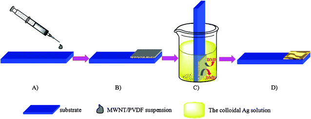 | ||
| Scheme 1 Preparation process of the Ag NPs/MWCNTs/PVDF composites viaphase inversion method. A) and B) spreading the MWCNTs/PVDF suspension on the substrate with a glass rod. C) Immediate immersion of the substrate in the colloidal Ag solution, and subsequent coagulation of the PVDF and incorporation of Ag NPs by the phase inversion method. D) Formation of Ag NPs/MWCNTs/PVDF composites. | ||
2.4 Electrocatalytic experiments
Prior to the surface coating, the ITO-glass electrodes were sonicated for 10 min in 1:1 nitric acid/water (v/v), acetone, and DI water successively, and then allowed to dry under nitrogen flow. Neat PVDF, MWCNTs/PVDF, Ag NPs/PVDF and Ag NPs/MWCNTs/PVDF composites were deposited on the surface of ITO-glass electrodes by the above-described procedure. Electrochemical impedance spectroscopy was performed in the presence of 10 mM K3[Fe(CN)6]/K4[Fe(CN)6] (1/1) mixture as a redox probe. The alternative voltage was 5 mV and the frequency range is 0.01–106 Hz. Cyclic voltammetric experiments were also carried out at a scan rate of 100 mV s−1 in 0.01 M Fe(CN)63−/4−. H2O2 electrocatalytic oxidation experiments were carried out in a 0.2 M PBS (pH = 7.0) containing 1.0 mM H2O2 at a scan rate of 50 mV s−1.
2.5 Characterizations
The X-ray photoelectron spectra were obtained with an ESCALab 220i-XL electron spectrometer from VG Scientific using 300 W Al Kα radiation. The base pressure was about 3 × 10⁻⁹ mbar. The binding energies were referenced to the C1s line at 284.8 eV from adventitious carbon. The morphologies of the films were visualized by scanning electron microscopy (SEM) on a JEOL JSM-6490 scanning electron microscopy at room temperature. Transmission electron microscopy (TEM) was carried out on a JEOL JEM 2100. The TGA curves were measured using a TGA Q500 (TA Instruments) operated in nitrogen atmosphere at a heating rate of 10 °C min−1. The FT-IR spectra was collected in attenuated total reflection (ATR) mode with the IR Tensor 27, Bruker Corp. DSC measurements of films were performed on a TA Q100 DSC system, over a temperature range from 20 to 200 °C at heating and cooling rates of 10 °C min−1 and a N2 flow of 50 mL min−1. Raman spectra were obtained at 514.5 nm laser excitation on a Renishaw Microscope System RM2000 at room temperature. Spectra were collected at various locations on each sample to determine the reproducibility. The CV and EIS experiments were performed on a CHI 600D electrochemical workstation (ChenHua Co, Shanghai, China). A conventional three-electrode cell was used at room temperature (25 °C), using neat PVDF and composite films on an ITO-coated glass substrate as the working electrode, a platinum electrode as an auxiliary electrode and an Ag/AgCl (saturated KCl) electrode as the reference electrode.3 Results and discussion
3.1 Morphology and interface structure viaphase inversion method
The phase inversion method is usually indicative of the porous inner structure for the resultant samples. As shown in Fig. 1, a honeycomb-like porous structure is revealed from neat PVDF (Fig. 1A), MWCNTs/PVDF (Fig. 1B), Ag NPs/PVDF (Fig. 1C) and Ag NPs/MWCNTs/PVDF (Fig. 1D) composites.25 Meanwhile, it can be clearly seen that the average pore size of Ag NPs/MWCNTs/PVDF composite became obviously larger than those of neat PVDF and other two composites (Fig. 1D).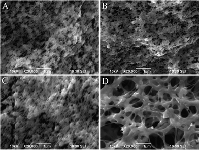 | ||
| Fig. 1 SEM images of neat PVDF (A), MWCNTs/PVDF (B), Ag NPs/PVDF (C) and Ag NPs/MWCNTs/PVDF (D) composites. | ||
Fig. 2 represents the typical TEM images of MWCNTs, MWCNTs/PVDF and Ag NPs/MWCNTs/PVDF composites. The images demonstrate that the MWCNTs surfaces of MWCNTs/PVDF (Fig. 2B) and Ag NPs/MWCNTs/PVDF (Fig. 2C) composites are covered by a polymeric layer, resulting from the adsorption of PVDF by the nonspecific molecular interactions between the C–H groups of PVDF and MWCNTs,30,31 while the purified MWCNTs (Fig. 2A) surfaces are very smooth with clear edges. It is also clear from Fig. 2C that Ag NPs (represented by black dots in the TEM image) are well dispersed in the surface of MWCNTs.
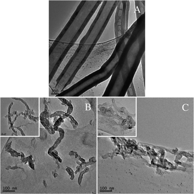 | ||
| Fig. 2 TEM images of the purified MWCNTs (A), MWCNTs/PVDF (B) and Ag NPs/MWCNTs/PVDF (C) composites. | ||
X-ray photoelectron spectroscopy (XPS) is employed to measure the elemental composition of the PVDF, MWCNTs/PVDF, Ag NPs/PVDF and Ag NPs/MWCNTs/PVDF composites (Fig. 3). As expected, strong signals from carbon (C1s) and fluorine (F1s and F2s) are observed for neat PVDF (Fig. 3A), Ag NPs/PVDF (Fig. 3B), MWCNTs/PVDF (Fig. 3C) and Ag NPs/MWCNTs/PVDF (Fig. 3D) composites. The signal of the Ag3d peak is observed in the expanded spectra for the Ag NPs/PVDF and Ag NPs/MWCNTs/PVDF composites, as shown in Fig. 3B and Fig. 3D, respectively. The peak energies of Ag3d5/2 and Ag3d3/2 locate at 368.0 ev and 374.0 ev, respectively,32 corresponding to the silver metallic state.33 The atomic concentration of silver is evaluated to be 0.08% for the Ag NPs/MWCNTs/PVDF composite, almost 3-times higher than that of the Ag NPs/PVDF composite (about 0.03%). As a result of the addition of MWCNTs that is typically used for metal supporting on carbon nanotubes,15 the mass loading of the Ag NPs onto the Ag NPs/MWCNTs/PVDF composite is dramatically improved up to 1.66 compared to that of the Ag NPs/PVDF composite (see Supporting Information)†. The enhanced loading of Ag particles via the adoption of MWCNTs is ascribed mainly to electrostatic interaction between MWCNTs and Ag NPs, supported by our complementary ξ potential test.
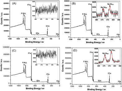 | ||
| Fig. 3 X-ray photoelectron spectra of neat PVDF (A), Ag NPs/PVDF (B), MWCNTs/PVDF (C), and Ag NPs/MWCNTs/PVDF (D) composites. The insets in the expanded spectra are detailed scan spectra of Ag3d. | ||
The interfacial interactions between polymer and carbon materials, such as MWCNTs, have also been studied using Raman spectroscopy.30,34–36 The Raman results of the MWCNTs/PVDF and Ag NPs/MWCNTs/PVDF composites are shown in Fig. 4. The purified MWCNTs have two characteristic peaks at 1352 and 1585 cm−1 which correspond to the D-band (the disordered graphite structure) and G-band (sp2-hybridized carbon), respectively.35 In comparison, the frequencies of the D-band and G-band of the both MWCNTs/PVDF and Ag NPs/MWCNTs/PVDF composites are slightly shifted upward to 1353 and 1586 cm−1, respectively. In addition, the ratio of D-band to G-band intensities (ID/IG) can directly describe the structure changes of MWCNTs.36 It is noticed that the value of ID/IG is shifted upward from 0.88 for purified MWCNTs to 1.03 and 1.31 for MWCNTs/PVDF and Ag NPs/MWCNTs/PVDF, respectively (Table S1, Supporting Information)†. According to previous reports, this phenomenon of the higher ID/IG ratio and the minor upshift of D- and G-bands is attributed to a strong donor–acceptor interaction between the MWCNTs and fluorine atom of PVDF at the interfaces.30,34,36
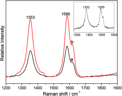 | ||
| Fig. 4 Raman spectra of the MWCNTs/PVDF (a) and Ag NPs/MWCNTs/PVDF (b) composites. Inset: the Raman spectra of purified MWCNTs. | ||
3.2 Polymorphs and thermal stability
As a typical semi-crystalline thermoplastic, PVDF possesses mainly non-polar α-phase and polar β-phase main crystal polymorphs.37 In this case, only one melting peak at ca.162 °C corresponding to α-phase appears for all samples, including the neat PVDF, Ag NPs/PVDF, MWCNTs/PVDF and AgNPs/MWCNTs/PVDF composites (Fig. S1B).38 This is consistent with the FT-IR result, in which the bands at 1383, 976, 795, 764, and 615 cm−1 are ascribed to α-phase crystals for all samples (Fig. S1A).39,40 Based on these results, it can be concluded that all the composites, as well as the neat PVDF are all α-phase crystals dominated. Meanwhile, it is also observed that the melting peak temperature (Tm) remained almost unchanged at 162 °C; whereas the degree of mass crystallinity (Xc) of the three composites, being derived from the calculated enthalpies concerning the melting of the PVDF component, decreased as compared with that of the neat PVDF and this trend is more evident in the presence of MWCNTs, i.e. MWCNTs/PVDF and Ag NPs/MWCNTs/PVDF (Table S2)†. This phenomenon could be ascribed to the two-edge effect from MWCNTs, i.e. on one hand, the nano-sized MWCNTs will act as a nucleating agent which is beneficial to the crystallization of PVDF; on the other hand, MWCNTs possess a remarkably high superficial area so that they will restrict the molecular motion of PVDF segment and thus interfere with the crystal growth.41 In addition, from the DSC cooling curve, no marked change detected in the crystallization temperature (Tc) for all samples (Fig. S1C). (Table S2, Fig. S1A, S1B and S1C, Supporting Information.)
Additionally, a distinct one-step, thermal degradation process is observed in the thermal gravimetric analysis (TGA) for neat PVDF, Ag NPs/PVDF, MWCNTs/PVDF and Ag NPs/MWCNTs/PVDF composites (Fig. S2)†. As indicated, the Ag NPs/MWCNTs/PVDF composites had the lowest initial degradation temperature (Ti), temperature at the highest degradation rate (Tmax) and weight loss rate at Tmax among the four samples, suggesting that the introduction of MWCNTs and Ag nanoparticles will slightly decrease the thermal stability of this PVDF membrane (Table S3, Fig. S2, Supporting Information). This observation can be interpreted as follows: MWCNTs possess high aspect ratio and high thermal conductivity,42 and thus when trace of MWCNTs is added and dispersed homogeneously in the polymer matrix, it will bring a considerable improvement on the thermal conductivity of the composite.43,44 In this context, more homogeneous dispersion of MWCNTs in the PVDF matrix will lead to a higher thermal conductivity of the hybrids. Moreover, Ag NPs also exhibits the largest thermal conductivities among all the metals.45,46 Therefore, the composite comprising of MWCNTs and Ag NPs will have high thermal conductivity, and thus leads the Ag NPs/MWCNTs/PVDF composite to have the higher Tc and lower thermal stability than the other three samples. Conclusively, the above observations from the thermal analysis, including TGA and DSC, and FT-IR measurements imply 1) the good dispersibility of MWCNTs and Ag NPs in the PVDF matrix and 2) good distribution of MWCNTs and Ag NPs will not bring detectable variation in the polymorphs of PVDF matrix.
3.3 Application of MWCNT-Based nanocomposites into electrochemistry and electrocatalysis
The combination of MWCNTs and noble metal nanoparticles are noted for their excellent electrocatalytic property.47,48 As a classical characterization, electrochemical impedance spectroscopy (EIS) is an effective method to probe the interface-related changes in capacitance and resistance to heterogeneous electron transfer. The advantage of EIS over other electrochemical techniques is that only small amplitude perturbations from the steady state are needed and information concerning the interface can be provided.49 In the EIS analysis, the linear part represents the diffusion-limited process, and the semicircle portion corresponds to the electron transfer-limited process. The electron transfer resistance (Ret) at the electrode surface is equal to the semicircle diameter. This resistance controls the electron transfer kinetics of the redox probe at the electrode interface. The corresponding Nyquist impedance plots are shown in Fig. 5A. As indicated, the PVDF-modified electrode had the largest semicircle, implying high Ret to the redox probe dissolved in electrolyte solution, which was caused by the great nonconductive properties of PVDF which acted as an inert electron layer and retarded the electron transfer. After MWCNTs were added into the PVDF, the resistance of MWCNTs/PVDF-modified electrode decreased compared with the PVDF-modified electrode. The reason is that MWCNTs have good conductivity and additionally MWCNTs/PVDF-modified electrodes have larger effective surface areas than the PVDF-modified electrode. Upon the further incorporation of Ag NPs, the Ret of Ag NPs/PVDF and Ag NPs/MWCNTs/PVDF-modified electrode decreased rapidly, in that the Ag NPs play a role similar to a conducting wire to promote electron transfer.50 Based on the results from Fig. 5A, we simulated the Randles equivalent circuit of the PVDF, Ag NPs/PVDF, MWCNTs/PVDF and Ag NPs/MWCNTs/PVDF composites (Fig. 5B). And we also calculated the values of Ret and the capacitances (Cdl) (Fig. 5C). As shown, the values of Ret decreased successively to the minimum value of 155.4 Ω (Ag NPs/MWCNTs/PVDF composites), and the values of Cdl increased in succession to reach the maximum value of 935 nF for Ag NPs/MWCNTs/PVDF composites. Therefore, the Ag NPs/MWCNTs/PVDF composite, comparing with the other three samples demonstrates lower resistance to heterogeneous electron transfer and also higher capacitance, which is beneficial for several electrochemical applications, including sensing/biosensing and battery applications.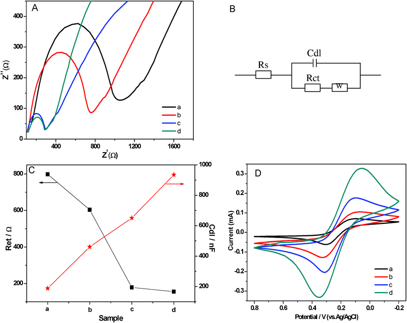 | ||
| Fig. 5 (A) Electrochemical impedance spectroscopy of neat PVDF (a), MWCNTs/PVDF (b), Ag NPs/PVDF (c) and Ag NPs/MWCNTs/PVDF (d) composite-modified IIO-glass electrodes for a 10 mM ferricyanide solution. (B) Randles equivalent circuit based on the electrochemical impedance spectroscopy. (C) The values of electron transfer resistance (Ret) and the capacitances (Cdl) of neat PVDF (a), MWCNTs/PVDF (b), Ag NPs/PVDF (c) and Ag NPs/MWCNTs/PVDF (d) composite-modified IIO-glass electrodes based on the electrochemical impedance spectroscopy. (D) Cyclic voltammograms resulting from the electrochemical properties of neat PVDF (a), MWCNTs/PVDF (b), Ag NPs/PVDF (c) and Ag NPs/MWCNTs/PVDF (d) composite-modified IIO-glass electrodes. Conditions: scan rate, 100 mV s−1; 0.01 mol L−1Fe(CN)63−/4−. | ||
Further, the cyclic voltammetry of ferricyanide shows that the oxidation/reduction signal of the ferrous/ferric couple at the Ag NPs/MWCNTs/PVDF composite-modified ITO-glass electrode is nearly two times higher than that at the Ag NPs/PVDF composite-modified ITO-glass electrode (10 mM; Fig. 5D). As seen, the magnitudes of the anodic current were 0.332 mA (at Epa (anode peak potential) = 349 mV) and 0.205 mA (at Epa = 312 mV) for Ag NPs/MWCNTs/PVDF and Ag NPs/PVDF composites, respectively; and the cathodic currents were 0.328 mA (at Epc (cathode peak potential) = 56 mV) and 0.176 mA (at Epc = 106 mV) for Ag NPs/MWCNTs/PVDF and Ag NPs/PVDF composite-modified ITO-glass electrodes, respectively (all potentials are uncorrected from ohmic drop). Hence, the obvious increase in the amperometric response implies that the electron transfer kinetics of Fe(CN)63−/4− is enhanced. Although the oxidation/reduction signals of the ferrous/ferric couple are very weak for neat PVDF and MWCNTs/PVDF composite-modified ITO-glass electrodes, a higher background current of the MWCNTs/PVDF composite-modified ITO-glass electrode than that of the PVDF composite-modified ITO-glass electrode—due to the higher capacitance of the MWCNTs/PVDF composite—appears and this observation is consistent with the above electrochemical impedance measurements.
The reliable, accurate, and rapid determination of H2O2 is of practical importance because it is an essential mediator in food, pharmaceutical, clinical, industrial and environmental analyses.17 Therefore, it is interesting to explore whether the as fabricated composites can be used as an candidate material for constructing a H2O2 electrochemical sensor with high performance. In the presence of 1.0 mM H2O2, an obviously catalytic current appears for the Ag NPs/MWCNTs/PVDF composite-modified ITO-glass electrode (Fig. 6). The peak potentials locate at −0.653 V and shifted positively as compared with that of the Ag NPs/PVDF composite-modified ITO-glass electrode −0.714 V. In contrast, the responses of H2O2 for the PVDF and MWCNTs/PVDF composite-modified ITO-glass electrode are significantly weak or non-detectable. These results suggest that the Ag NPs/MWCNTs/PVDF composite-modified ITO-glass electrode possess a significant catalytic ability to H2O2 reduction and the catalytic current is mainly come from the Ag NPs on the electrocatalytic reduction of H2O2.51,52 In addition, it is noteworthy that a current of the Ag NPs/MWCNTs/PVDF composite-modified ITO-glass electrode is higher than that of the Ag NPs/PVDF composite-modified IIO-glass electrode, which is ascribed to the higher Ag NPs loading efficiency of the Ag NPs/MWCNTs/PVDF composite than of the Ag NPs/PVDF composite, as evidenced by the above-mentioned XPS results (see Fig. 3). Fig. 7 displays the typical amperometric responses of Ag NPs/MWCNTs/PVDF (A) and Ag NPs/PVDF (B) composites-modified ITO-glass electrode upon successive additions of different concentration H2O2 into the stirring 0.2 M PBS solution (pH = 7.0). As exhibited in the inset of Fig. 7A, a wide linear response to H2O2 of Ag NPs/MWCNTs/PVDF composite-modified ITO-glass electrode ranging from 50 to 810 μM can be observed with a quite fast response (about 4 s), while the Ag NPs/PVDF composite-modified ITO-glass electrode exhibits an insensitive response to H2O2 with a non-linear range from 50 to 810 μM (the inset of Fig. 7B). The fast response can be attributed to the fact that H2O2 can rapidly diffuse into the Ag NPs/MWCNTs/PVDF composite, owing to the porous structure as demonstrated in Fig. 1D and the uniform dispersion of Ag NPs shown in Fig. 2C. By calculation, the sensitivity of this Ag NPs/MWCNTs/PVDF composite-modified ITO-glass electrode toward H2O2 reduction was ca. 12.22 μA mM−1 cm−2, nearly comparable to 15.6 μA mM−1 cm−2 as previously reported for MWCNTs/gold NPs/polyethylenimine-functionalized ionic liquid thin film, in which the content of gold NPs was 18.9% (wt).17 This result also reveals that the as-prepared Ag NPs/MWCNTs/PVDF composite possess a good electrocatalytic activity towards H2O2.
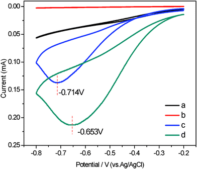 | ||
| Fig. 6 Cyclic voltammograms (CVs) of different electrodes in PBS solution (0.2 M, pH = 7.0) and 1.0 mM H2O2: neat PVDF (a), MWCNTs/PVDF (b), Ag NPs/PVDF (c) and Ag NPs/MWCNTs/PVDF (d) composite-modified ITO-glass electrodes. Scan rate: 0.05 mv/s. | ||
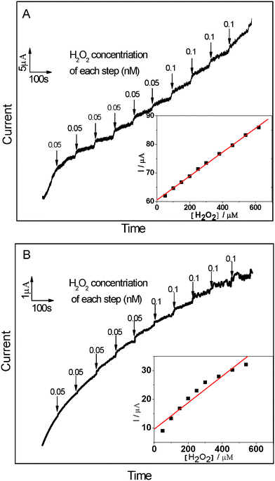 | ||
| Fig. 7 Chronoamperometric response of Ag NPs/MWCNTs/PVDF (A) and Ag NPs/PVDF (B) composite-modified ITO-glass electrodes on the successive injection of H2O2 into stirring air-saturated PBS (0.2 M, pH = 7.0). Working potential: −0.6 V and −0.7 V for Ag NPs/MWCNTs/PVDF and Ag NPs/PVDF composite-modified ITO-glass electrode, respectively. Inset: The plot of electrocatalytic current of H2O2versus its concentrations. | ||
4 Conclusion
In summary, we have constructed Ag NPs/MWCNTs/PVDF composites by blending PVDF with MWCNTs, followed by the incorporation of Ag NPs into MWNT/PVDF composites viaphase inversion method. As indicated, this relatively simple strategy will allow the Ag NPs with a higher loading efficiency and dispersion uniformity, in the presence of MWCNTs. And for the composites, the Ag NPs will not bring marked disturbance on the polymorph, crystallization behavior or the thermal stability of the polymeric matrix. More importantly, the Ag NPs/MWCNTs/PVDF composite-modified ITO-glass electrode shows a high electrocatalytic activity toward the reduction of H2O2. We believe that this strategy of nanocomposite fabrication is expandible to other noble metals NPs, such as Au NPs, Pt NPs and Pd NPs, to construct the functional nanomaterials with tunable uploading and good distribution of metal NPs in the MWCNTs/polymers. Additionally, the homogeneity and stability of the films will surely open up a range of potential applications in the electrocatalytic device and biosensor, for example.Acknowledgements
This work was supported by the National Foundation of Nature Science (21072221,21172252), President Fund of Graduate University of CAS (095101CY00), and grant KF2008-04 from the State Key Laboratory of Environmental Chemistry and Ecotoxicology, Research Center for Eco-Environmental Sciences, Chinese Academy of Sciences.References
- Y. Zhao, L. Fan, H. Zhong, Y. Li and S. Yang, Adv. Funct. Mater., 2007, 17, 1537–1541 CrossRef CAS.
- B. X. Yang, J. H. Shi, K. P. Pramoda and S. H. Goh, Nanotechnology, 2007, 18, 125606/1–7 CAS.
- U. D. Weglikowska, M. Kaempgen, B. Hornbostel, V. Skakalova1, J. P. Wang, J. D. Liang and S. Roth, Phys. Status Solidi B, 2006, 243, 3440–3444 CrossRef.
- N. Grossiord, H. E. Miltner, J. Loos, J. Meuldijk, B. V. Mele and C. E. Koning, Chem. Mater., 2007, 19, 3787–3792 CrossRef CAS.
- S. Sergei, L. Xue, O. Rahmi, K. Pawel and G. C. David, J. Appl. Phys., 2004, 95, 8136–8144 CrossRef.
- B. J. Landi, R. P. Raffaelle, M. J. Heben, J. L. Alleman, W. V. Derveer and T. Gennett, Nano Lett., 2002, 2, 1329–1332 CrossRef CAS.
- H. Cai, Y. Xu, P. G. He and Y. Z. Fang, Electroanalysis, 2003, 15, 1864–1870 CrossRef CAS.
- E. Frackowiak, V. Khomenko, K. Jurewicz, K. Lota and F. Béguin, J. Power Sources, 2006, 153, 413–418 CrossRef CAS.
- C. F. Zhou, S. Kumar, C. D. Doyle and J. M. Tour, Chem. Mater., 2005, 17, 1997–2002 CrossRef CAS.
- D. Tabuani, O. Monticelli, A. Chincarini, C. Bianchini, F. Vizza, S. Moneti and S. Russo, Macromolecules, 2003, 36, 4294–4301 CrossRef CAS.
- S. Kidambi and M. L. Bruening, Chem. Mater., 2005, 17, 301–307 CrossRef CAS.
- J. Huang, D. Wang, H. Hou and T. You, Adv. Funct. Mater., 2008, 18, 441–448 CrossRef CAS.
- R. J. Cui, C. Liu, J. M. Shen, D. Gao, J. J. Zhu and H. Y. Chen, Adv. Funct. Mater., 2008, 18, 2197–2204 CrossRef CAS.
- H. S. Qian, M. Antonietti and S. H. Yu, Adv. Funct. Mater., 2007, 17, 637–643 CrossRef CAS.
- A. Carrillo, J. A. Swartz, J. M. R. Gamba, S. Kane, N. Chakrapani, B. Wei and P. M. Ajayan, Nano Lett., 2003, 3, 1437–1440 CrossRef CAS.
- M. Okamoto, T. Fujigaya and N. Nakashima, Small, 2009, 5, 735–740 CrossRef CAS.
- F. Jia, C. S. Shan, F. H. Li and L. Niu, Biosens. Bioelectron., 2008, 24, 945–950 CrossRef CAS.
- H. Strathmann and K. Kock, Desalination, 1977, 21, 241–255 CrossRef CAS.
- L. A. Abdul, I. Suzylawati and B. Subhash, Desalination, 2003, 157, 87–95 CrossRef.
- K. Kohichi, J. Biochem. Biophys. Methods, 2001, 49, 241–251 CrossRef.
- S. Marais, J. M. Saiter, C. Devallencourt, Q. T. Nguyen and M. Metayer, Polym. Test., 2002, 21, 425–431 CrossRef CAS.
- S. Marais, E. Bureau, F. Gouanve, E. B. Salem, Y. Hirata, A. Andrio, C. Cabot and H. Atmani, Polym. Test., 2004, 23, 475–486 CrossRef CAS.
- Y. H. Zhao, B. K. Zhu, X. T. Ma and Y. Y. Xu, J. Membr. Sci., 2007, 290, 222–229 CrossRef CAS.
- Y. H. Zhao, Y. L. Qian, B. K. Zhu and Y. Y. Xu, J. Membr. Sci., 2008, 310, 567–576 CrossRef CAS.
- Y. H. Zhao, Y. Y. Xu and B. K. Zhu, Solid State Ionics, 2009, 180, 1517–1524 CrossRef CAS.
- S. Sánchez, E. Fábregas, H. Iwai and M. Pumera, Small, 2009, 5, 795–799 CrossRef.
- Z. W. Zhang, Q. Xu, Z. M. Chen and J. Yue, Macromolecules, 2008, 41, 2868–2873 CrossRef CAS.
- C. N. Lok, C. M. Ho, R. Chen, Q. Y. He, W. Y. Yu, H. Z. Sun, P. K. H. Tam, J. F. Chiu and C. M. Che, J. Proteome Res., 2006, 5, 916–924 CrossRef CAS.
- H. Dong, D. Wang, G. Sun and J. P. Hinestroza, Chem. Mater., 2008, 20, 6627–6632 CrossRef CAS.
- L. H. He, X. L. Zheng and Q. Xun, J. Phys. Chem. B, 2010, 114, 5257–5262 CrossRef CAS.
- D. Baskaran, J. W. Mays and M. S. Bratcher, Chem. Mater., 2005, 17, 3389–3397 CrossRef CAS.
- Y. Gao, P. Jiang, D. F. Liu, H. J. Yuan, X. Q. Yan, Z. P. Zhou, J. X. Wang, L. Song, L. F. Liu, W. Y. Zhou, G. Wang, C. Y. Wang and S. S. Xie, J. Phys. Chem. B, 2004, 108, 12877–12881 CrossRef CAS.
- V. K. Kaushik, J. Electron Spectrosc. Relat. Phenom., 1991, 56, 273–277 CrossRef CAS.
- S. Huang, W. A. Yee, W. C. Tjiu, Y. Liu, M. Kotaki, Y. C. F. Boey, J. Ma, T. X. Liu and X. H. Lu, Langmuir, 2008, 24, 13621–13626 CrossRef CAS.
- B. K. Price, J. L. Hudson and J. M. Tour, J. Am. Chem. Soc., 2005, 127, 14867–14870 CrossRef CAS.
- Q. Yang, L. Shuai and X. Pan, Biomacromolecules, 2008, 9, 3422–3426 CrossRef CAS.
- R. M. Briber and F. Khoury, J. Polym. Sci., Part B: Polym. Phys., 1993, 31, 1253–1272 CrossRef CAS.
- J. S. Andrew and D. R. Clarke, Langmuir, 2008, 24, 8435–8438 CrossRef CAS.
- M. Benz, W. B. Euler and O. J. Gregory, Macromolecules, 2002, 35, 2682–2688 CrossRef CAS.
- A. K. Dikshit and A. K. Nandi, Macromolecules, 2000, 33, 2616–2625 CrossRef CAS.
- L. H. He, Q. Xu, C. W. Hua and R. Song, Polymer Composites, 2010, 31, 921–927 CAS.
- C. W. Nan, G. Liu, Y. H. Lin and M. Li, Appl. Phys. Lett., 2004, 85, 3549–3551 CrossRef CAS.
- Y. S. Song and J. R. Youn, Carbon, 2005, 43, 1378–1385 CrossRef CAS.
- Z. D. Han and A. Fina, Prog. Polym. Sci., 2010 DOI:10.1016/j.progpolymsci.2010.11.004.
- G. D. Liang, S. P. Bao and S. C. Tjong, Mater. Sci. Eng., B, 2007, 142, 55–61 CrossRef CAS.
- Y. Sun and Y. Xia, Adv. Mater., 2002, 14, 833–837 CrossRef CAS.
- L. Qu, Y. Liu, J. B. Baek and L. Dai, ACS Nano, 2010, 4, 1321–1326 CrossRef CAS.
- H. J. Choi, I. Y. Jeon, D. W. Chang, D. S. Yu, L. Dai, L. S. Tan and J. B. Baek, J. Phys. Chem. C, 2011, 115, 1746–1751 CAS.
- S. Hleli, C. Martelet, A. Abdelghani, F. Bessueille, A. Errachid, J. Samitier, H. C. W. Hays, P. A. Millner, N. Burais and N. Jaffrezic-Renault, Mater. Sci. Eng., C, 2006, 26, 322–327 CrossRef CAS.
- X. Che, R. Yuan, Y. Q. Chai, J. J. Li, Z. J. Song and J. F. Wang, J. Colloid Interface Sci., 2010, 345, 174–180 CrossRef CAS.
- K. Cui, Y. H. Song, Y. Yao, Z. Z. Huang and L. Wang, Electrochem. Commun., 2008, 10, 663–667 CrossRef CAS.
- L. Yao, W. Y. Yang, J. Yang, L. H. He, J. Sun, R. Song, Z. Ma and W. Huang, Nanoscale, 2011, 3, 916–918 RSC.
Footnote |
| † Electronic Supplementary Information (ESI) available: The calculation about the loading of the Ag NPs; D- and G-bands shifts and Raman ID/IG intensity ratios; DSC and TG parameters; FTIR spectra; DSC and TG curves. See DOI: 10.1039/c1ra00672j/ |
| This journal is © The Royal Society of Chemistry 2012 |