One-pot green synthesis of Ag nanoparticles-graphene nanocomposites and their applications in SERS, H2O2, and glucose sensing†
Yingwei
Zhang
a,
Sen
Liu
a,
Lei
Wang
a,
Xiaoyun
Qin
a,
Jingqi
Tian
ab,
Wenbo
Lu
a,
Guohui
Chang
a and
Xuping
Sun
*a
aState Key Lab of Electroanalytical Chemistry, Changchun Institute of Applied Chemistry, Chinese Academy of Sciences, Changchun, 130022, Jilin, China. E-mail: sunxp@ciac.jl.cn; Fax: (+86) 431-85262065; Tel: (+86) 431-85262065
bGraduate School of the Chinese Academy of Sciences, Beijing, 100039, China
First published on 10th November 2011
Abstract
In this contribution, we demonstrate a green, cost-effective, one-pot preparative route toward Ag nanoparticles-graphene (AgNPs–G) nanocomposites in aqueous solution with the use of tannic acid (TA), an environmentally friendly and water-soluble polyphenol, as a reducing agent. Such AgNPs–G nanocomposites were synthesized through one-pot reduction of AgNO3 and GO by TA. We investigated surface enhanced Raman scattering (SERS) and electrochemical properties of the resultant AgNPs–G nanocomposites. It is found that such AgNPs–G nanocomposites show excellent SERS activity as SERS substrates and exhibit notable catalytic performance toward the reduction of H2O2. This enzymeless H2O2 sensor has a fast amperometric response time of less than 2 s. The linear range is estimated to be from 1 × 10⁻⁴ M to 0.01 M (r = 0.999) and the detection limit is estimated to be 7 × 10⁻⁶ M at a signal-to-noise ratio of 3. A glucose biosensor was further fabricated by immobilizing glucose oxidase (GOD) into chitosan–AgNPs–G nanocomposite film on the surface of a glassy carbon electrode (GCE). This sensor exhibits good response to glucose, and the linear response range is estimated to be from 2 to 10 mM (R = 0.996) at −0.5 V. The detection limit of 100 μM was achieved at a signal-to-noise ratio of 3. More importantly, we demonstrate successfully its application for glucose detection in human blood serum.
1. Introduction
Since Geim and co-workers at Manchester University first isolated single-layer samples from graphite in 2004, graphene (G), a monolayer of sp2-bonded carbon atoms tightly packed into a two-dimensional (2D) honeycomb lattice, and characterized as “the thinnest material in our universe”, has attracted tremendous attention in recent years due to its high surface area (∼2600 m2 g−1), high chemical stability, and unique electronic, mechanical properties.1 Therefore, numerous efforts have been made to explore its potential applications in many technological fields, such as nanoelectronics,2 nanophotonics,3 batteries,4 chemical and biological sensors.5 However, the first challenge for the practical applications of G is realizing its high economical accessibility and easy processing of G nanosheets. Up to now, numerous techniques such as micromechanical exfoliation,1a chemical vapor deposion,6 chemical reduction of graphene oxide (GO),7 electrochemical reduction of GO,8 photoreduction of GO,9 and other special stratagies10etc. have been successfully developed for synthesis of G. Among them, the chemical reduction of GO holds the great advantage of low cost and bulk quantity production.11 However, reduction reagents such as hydrazine and its derivative are toxic and, on the other hand, the strong van der Waals interaction between the reduced G sheets causes them to aggregate in solution, limiting its further application.12 This issue was subsequently circumvented by using environmentally friendly reducing agents for preparation of G. Up to now, however, only limited nontoxic agents including sugar, chitosan, dopamine, dextran, protein, L-ascorbic acid and poly(N-vinyl-2-pyrrolidone) (PVP) have been successfully developed to prepare G by a green route.13 Accordingly, developing new environmentally friendly reducing agents for preparation of G is highly desired.Nanocomposites have aroused extensive interest over past decades due to their new optical, electronic, thermal, mechanical, and catalytic properties.14 Due to the large surface area and the above mentioned excellent properties, G has been an attractive choice as the matrix for nanocomposites.15 Hence, there are increasing reports of composites which integrate GO or G with different nanoscaled materials.16 Among them, metal-G nanocomposites are very useful in various engineering applications such as fuel cell catalysis,17 electrochemical energy storage18 and especially electrochemical sensing.19 This is because metal-G nanocomposites could provide larger electrochemically active surface areas and effectively accelerate the electron transfer between electrode and detection molecules, which could lead to a more rapid and sensitive current response. However, the metal-G nanocomposites are usually obtained from in situreduction of metallic salts on preformed G sheets or the decoration of G sheets with presynthesized nanoparticles, which increased the complexity of the process. Furthermore, the resulting composites are mostly in the form of aggregation due to π–π stacking interactions between G nanosheets. Therefore, a one-pot route for synthesizing well-dispersed metal-G nanocomposites with high performance is highly required.
Herein, we report a facile, cost-effective, environmentally friendly, one-pot method to synthesize Ag nanoparticles-G nanocomposites (AgNPs–G) with the use of tannic acid (TA, Fig. S1†), a water-soluble, phenolic hydroxyl-rich compound and widely present in woods, as a reducing agent. Scheme 1 presents a scheme (not to scale) to illustrate the proposed one-pot preparation of AgNPs–G nanocomposites via chemical reduction of AgNO3 and GO by TA. The resultant AgNPs–G nanocomposites show excellent SERS activity as SERS substrates and exhibit notable catalytic performance toward H2O2 reduction. More importantly, we demonstrate successfully its application for glucose detection in both buffer and human blood serum.
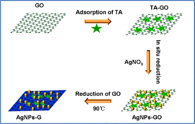 | ||
| Scheme 1 A scheme (not to scale) to illustrate the proposed one-pot preparation of AgNPs–G nanocomposites via chemical reduction of AgNO3 and GO by TA. | ||
2. Experimental
2.1 Materials
Graphite powder, TA, H2O2 (30 wt%), glucose, Na2HPO4, and NaH2PO4 were purchased from Aladin Ltd. (Shanghai, China). p-Aminothiophenol (p-ATP), glucose oxidase (GOD) and AgNO3 were purchased from Aldrich Chemical Comp. All chemicals were used as received without further purification. The water used throughout all experiments was purified through a Millipore system. Phosphate buffer saline (PBS) was prepared by mixing stock solutions of NaH2PO4 and Na2HPO4 and a fresh solution of H2O2 was prepared daily.2.2 Preparation of GO
GO was prepared from natural graphite powder through a modified Hummers method.20 In a typical synthesis, 1 g of graphite was added into 23 mL of 98% H2SO4, followed by stirring at room temperature over a period of 24 h. After that, 100 mg of NaNO3 was introduced into the mixture and stirred for 30 min. Subsequently, the mixture was kept below 5 °C by ice bath, and 3 g of KMnO4 was slowly added into the mixture. After heating to 35–40 °C, the mixture was stirred for another 30 min. After that, 46 mL of water was added into the above mixture during a period of 25 min. Finally, 140 mL of water and 10 mL of H2O2 were added into the mixture to stop the reaction. After the unexploited graphite in the resulting mixture was removed by centrifugation, as-synthesized GO was dispersed into individual sheets in distilled water at a concentration of 0.5 mg mL−1 with the aid of ultrasound for further use.2.3 Synthesis of AgNPs-G nanocomposites
In a typical experiment, 1 mL of GO was dispersed in 2 mL of 5 mg mL−1TA aqueous solution under ultrasonic irradiation for 30 min. Next, 100 μL of 25 mM AgNO3 aqueous solution and 4 μL of 0.3 M NaOH aqueous solution were added into the above TA-GO dispersion at room temperature, followed by an obvious color change from brown to brown yellow and accompanied by the presence of precipitates. At last, the resulting mixture was heated at 90 °C over a period of 1 h in a water bath to perform the reduction of GO. The products in the brown black dispersion were centrifuged and washed twice with distilled water to remove the excess TA and redispersed in water for characterization and further use.2.4 Preparation of AgNPs
For comparison, AgNPs were prepared with the use of TA as a reducing and stabilizing agent. In brief, 100 μL of 25 mM AgNO3 aqueous solution and 4 μL of 0.3 M NaOH aqueous solution were added into 2 mL of 5 mg mL−1TA aqueous solution. The solution was kept at room temperature for approximately 1 h.2.5 SERS experiments
In the SERS experiments, p-ATP was used as the probe molecule. Soaking was used to adsorb the molecule on the surfaces of AgNPs–G nanocomposites. 50 μL of p-ATP aqueous solutions with concentration of 2 × 10⁻⁸ M was mixed with 10 μL of as-prepared AgNPs–G nanocomposites. After shaking several times, the mixture was allowed to stay for 3 h to reach the adsorption equilibrium for direct SERS detection in liquid environment.2.6 Fabrication of AgNPs–G nanocomposites-modified glassy carbon electrode (GCE)
The modified electrodes were prepared by a simple casting method. Prior to the surface coating, the GCE was polished with 1.0 and 0.3 μm alumina powder, respectively, and rinsed with doubly distilled water, followed by sonication in ethanol solution and doubly distilled water successively. Then, the electrode was allowed to dry in a stream of nitrogen. To obtain the AgNPs–G nanocomposites-modified GCE, 3 μL of the AgNPs–G nanocomposites dispersion was dropped on the clean surface of GCE, and then 1.5 μL of chitosan (0.5%) solution was also dropped for stabilizing it. Finally, the electrode was allowed to dry in ambient air to obtain chitosan/AgNPs–G/GCE. For the control experiments, 3 μL of TA-reduced G (TA-G) and 1.5 μL of chitosan (0.5%) solution were also dropped on the clean surface of GCE to obtain chitosan/TA-G/GCE. Next, for the experiments of glucose detection, the chitosan/GOD/AgNPs–G/GCE was also prepared by the same method except for an extra dropping of 3 μL of 40 mg mL−1GOD, and then the electrode was dried at 4 °C for 2 h.2.7 Characterization
Transmission electron microscopy (TEM) measurement was made on a HITACHI H-8100 EM (Hitachi, Tokyo, Japan) with an accelerating voltage of 200 kV. UV-visible absorption spectra were obtained on a UV-5800 Spectrophotometer. Atomic force microscopic (AFM) images were recorded by using a Nanoscope MultiMode-V scanning probe microscopy (SPM) system (Veeco, USA). The samples were drop-cast on freshly cleaved mica and dried at room temperature. SERS spectra were collected with a Renishaw 2000 model confocal microscopy Raman spectrometer with a CCD detector and a holographic notch filter (Renishaw Ltd., Gloucestershire, U.K.) at ambient conditions. Radiation of 514.5 nm from an air-cooled argon ion laser was used for the SERS excitation. X-Ray photoelectron spectroscopy (XPS) analysis was measured on an ESCALABMK II X-ray photoelectron spectrometer using Mg as the exciting source. Electrochemical measurements are performed with a CHI 660D electrochemical analyzer (CH Instruments, Inc., Shanghai). A conventional three-electrode cell was used, including a GCE (geometric area = 0.07 cm2) as the working electrode, a Ag/AgCl (saturated KCl) electrode as the reference electrode, and platinum foil as the counter electrode. The potentials are measured with a Ag/AgCl electrode as the reference electrode. All the experiments were carried out at ambient temperature.3. Results and discussion
3.1 UV-visible absorption spectra, Raman, XPS and TEM characterization of AgNPs–G nanocomposites
The successful preparation of AgNPs–G nanocomposites was firstly confirmed by UV-vis absorbance spectra, as shown in Fig. 1. Curve a showed the absorption peaks of TA located at 214 and 274 nm, which were assigned to π–π* and n–π* transitions, respectively.21 The UV-vis spectrum of GO showed two absorption peaks at 230 nm and 300 nm (curve b). In the suspension of TA-GO, the n–π* absorbance peak of TA was blue shifted to 268 nm, as shown in curve c, indicating the presence of π–π interaction between the aromatic rings of TA and GO sheets.21 After the addition of 100 μL AgNO3 into the suspension of TA-GO, we obtained a new absorbance band centered at 415 nm characteristic of the colloidal Ag surface plasmon resonance band,22 providing evidence to support the formation of Ag nanoparticles (curve d). The spontaneous formation of Ag nanoparticles in our present study can be attributed to the direct redox between TA and Ag+, where Ag+ is reduced to metallic Ag by the phenolic hydroxyls of TA. Indeed, bayberry tannin as a phenolic hydroxyl-rich compound has recently been successfully used as a reducing agent and stabilizing agent for the synthesis of Au nanoparticles and Pd nanoparticles.23 Curve e is the UV-vis spectrum of the resultant AgNPs-G nanocomposites after heat treatment, and the peak of n–π* transition is further blue shifted to 263 nm, due to the strengthened interaction between G and the TA aromatic ring for the removal of oxygenic groups.21Fig. 1 inset shows photographs of the corresponding samples and a distinct color change from brown yellow to black can be observed after heat treatment. Such observation provides another piece of evidence to support the formation of well-dispersed AgNPs–G nanocomposites.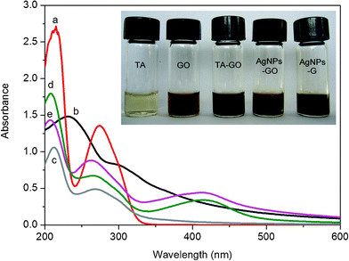 | ||
| Fig. 1 UV-vis absorption of aqueous dispersions of (a) TA; (b) GO; (c) TA-GO; (d) AgNPs–GO nanocomposites; (e) AgNPs–G nanocomposites. Inset: optical images of corresponding samples. | ||
TA is a mild reducing agent with a redox potential from −0.57 to −1.05 V (pH = 3.03–6.24).24 Compared with the redox potential of −0.82 to −1.09 V needed for GO,25 the reduction of GO by TA is thermodynamically favoured and there has been a recent successful report.21 In our study, the successive reduction of GO and AgNO3 to AgNPs-G nanocomposites by TA was further verified by Raman spectroscopy and X-ray photoelectron spectroscopy (XPS), as shown in Fig. S2 and Fig. S3.† It is well-known that G obtained by chemical reduction of GO exhibits two characteristic main peaks: the D band at ∼1350 cm−1, arising from a breathing mode of κ-point photons of A1g symmetry; and the G band at ∼1575 cm−1, arising from the first order scattering of the E2g phonon of sp2 C atoms. In our present study (Fig. S2†), it is seen that GO exhibits a D band at 1357 cm−1 and a G band at 1608 cm−1, while the corresponding bands of AgNPs–G nanocomposites are 1357 and 1593 cm−1, respectively. The G band of AgNPs–G nanocomposites that red-shifts from 1608 to 1593 cm−1 is attributed to the high ability for recovery of the hexagonal network of carbon atoms. It is also found that AgNPs–G nanocomposites shows relative higher intensity of D to G bands (1.08) than that of GO (0.83). These observations further confirm the formation of new graphitic domains after the heat treatment process.26 Fig. S3† shows the C1sXPS spectra of GO and AgNPs–G nanocomposites, respectively. The C1sspectra of GO and AgNPs–G nanocomposites could be deconvoluted into three peaks at 284.5, 285.6, and 288.4 eV, which are associated with C–C, C–O, and C![[double bond, length as m-dash]](https://www.rsc.org/images/entities/char_e001.gif) O, respectively. It is seen that the peak intensity of C–O is strong in GO (Fig. S3a†); In contrast, after a heat treatment process, the peak intensity of C–O in AgNPs–G nanocomposites (Fig. S3b†) is tremendously reduced. Note that TA consists of a large amount of –OH and –COOH, and thus makes a much greater contribution to the intensity of C–O and CO peaks in AgNPs–G nanocomposites. All the observations suggest that the most oxygen-containing functional groups are successfully removed after the heat treatment process.27 The XPS pattern of the resulting AgNPs–G nanocomposites also shows significant Ag 3d signals corresponding to the binding energy of metal Ag (Fig. S3c†),28 which further supports the conclusion that AgNPs have been effectively assembled on the surface of G nanosheets.
O, respectively. It is seen that the peak intensity of C–O is strong in GO (Fig. S3a†); In contrast, after a heat treatment process, the peak intensity of C–O in AgNPs–G nanocomposites (Fig. S3b†) is tremendously reduced. Note that TA consists of a large amount of –OH and –COOH, and thus makes a much greater contribution to the intensity of C–O and CO peaks in AgNPs–G nanocomposites. All the observations suggest that the most oxygen-containing functional groups are successfully removed after the heat treatment process.27 The XPS pattern of the resulting AgNPs–G nanocomposites also shows significant Ag 3d signals corresponding to the binding energy of metal Ag (Fig. S3c†),28 which further supports the conclusion that AgNPs have been effectively assembled on the surface of G nanosheets.
Fig. 2 shows the TEM images of these samples thus formed. Fig. 2a shows a TA-functionalized GO sheet in the suspension of TA-GO. After the addition of AgNO3 into the suspension of TA-GO, it is seen that the GO sheet has been decorated with a large amount of Ag nanoparticles about several nanometres to 20 nm in diameter (Fig. 2b and 2c). When the reaction mixture was further heated at 90 °C for 1 h, GO was reduced to G based on previous characterization and the G sheet decorated with many Ag nanoparticles can be observed (Fig. 2d).
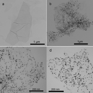 | ||
| Fig. 2 TEM image of the samples: (a) TA-GO; (b, c) AgNPs–GO nanocomposites and (d) AgNPs–G nanocomposites. | ||
3.2 SERS activity of AgNPs–G nanocomposites
To evaluate the SERS activity of the AgNPs–G nanocomposites, p-aminothiophenol (p–ATP) was used as a model Raman probe. Because it has been well-characterized by SERS and most of the prominent Raman bands have been assigned.29Fig. 3 displays the SERS spectra for 1 × 10⁻⁸ M p–ATP with the G, Ag NPs and AgNPs–G nanocomposites as SERS substrates, respectively. As shown in curve b, there are no apparent Raman peaks of p–ATP detected on the surface of G without AgNPs. Compared to the spectrum of the solid p–ATP (curve a), the SERS spectrum obtained on AgNPs–G nanocomposites (curve d) shows distinct frequency shifts for some changes in band intensity. The υCS band shifts from 1092 cm−1 to 1074 cm−1, and another frequency shift from 1598 cm−1 to 1580 cm−1 was also observed. Such observations clearly show that the –SH group of p–ATP makes direct contact with the AgNPs by forming a strong Ag–S bond.30 The Raman spectrum of p–ATP on the AgNPs–G nanocomposites exhibited four b2 modes at 1580, 1442, 1394, and 1143 cm−1 and one a1 mode at 1074 cm−1, which is quite similar to those of p–ATP absorbed on Ag nanoparticles.31 The two peaks at 1394 and 1442 cm−1 are caused by the formation of p,p′–dimercaptoazobenzene produced from p–ATP by selective catalytic coupling reaction on the Ag surface.32AFM data shown in Fig. S4† reveal the average thickness of the resultant G sheet ranges from 2.4 to 4.0 nm. Given TA molecules are anchoring on the surface of G and the thickness of single-layer G is about 1.0 nm,21,33 it is believed that most of the G sheets exist in the form of a mixture with bilayer and trilayer. It is established that SERS activity is sensitive to the layer number of mechanically exfoliated G and single-layer G provides much larger SERS enhancement than few-layer G due to that the π–π interactions between pure G layers degrades G's characteristics.34,35 In our present study, the SERS intensity of the p–ATP on the AgNPs–G nanocomposites (curve d) is much stronger than that on the AgNPs (curve c) with the same concentration of p–ATP. It indicates that such few-layer G (bilayer and trilayer), although obtained by chemical reduction of GO, can also provide SERS enhancement and thus the AgNPs–G can serve as an effective substrate for SERS application. The observed enhancement can be attributed to the increasing density of AgNPs on the surface of G sheets as “hot spots” for strong localized electromagnetic fields produced by the gaps between neighboring AgNPs and the strong electronic interactions of the AgNPs and the G sheet.35,36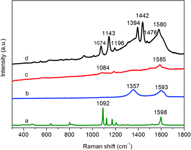 | ||
| Fig. 3 (a) Raman spectrum of solid p–ATP, SERS spectra of p–ATP (1 × 10⁻⁸ M) on (b) G, (c) AgNPs, and (d) AgNPs–G nanocomposites. | ||
To determine the enhancement effect of p–ATP on the AgNPs–G nanocomposites quantitatively, we calculated the SERS enhancement factor (EF) values of p–ATP in the AgNPs–G nanocomposites using the following expression: EF = (ISERS/Nads)/(Ibulk/Nbulk), Where ISERS stands for the intensity of a vibrational mode in the SERS spectrum of p–ATP and Ibulk for that of a solid sample. Nabs and Nbulk are the number of p–ATP molecules adsorbed on the SERS substrate and bulk molecules illuminated by the laser light to obtain the corresponding SERS and ordinary Raman spectra, respectively. Nads can be obtained according to the reported method,37 which is Nads = NdAlaserAN/σ, Where Nd is the number density of the AgNPs on the AgNPs–G nanocomposites, Alaser is the area of the focal spot of laser, AN is the AgNPs footprint area, and σ is the surface area occupied by an adsorbed p–ATP molecule. Nd and AN can be obtained from the TEM image shown in Fig. 2d, and Alaser is estimated to be 1 μm from the diameter of the laser spot. It was reported that each p–ATP molecule occupies about 0.20 nm2, indicating that σ can be adopted as 0.20 nm2/molecule.38 The total number of surface adsorbed molecules (Nads) within the illuminated laser spot can then be obtained at 2.15 × 10⁶. Nbulk is the molecule number of the solid p–ATP in the laser illumination volume. In our experiment, the laser spot of 1 μm in diameter and the penetration depth (2 μm) of the focused laser beam are used. Since the density of the solid p–ATP is 1.18 g cm−3, Nbulk was calculated to be about 8.9 × 10⁹ within the illuminated laser light. Taking the intensity at 1074 cm−1 (curve d) and 1092 cm−1 (curve a) into account, the EF at the AgNPs–G nanocomposites for the band located at 1074 cm−1 can be calculated to be as large as 2.16 × 10³ at 514 nm excitation.
3.3 Enzymeless electrochemical sensor for H2O2 detection
To demonstrate the electrochemical sensing application of such AgNPs–G nanocomposites, we first constructed an enzymeless H2O2 sensor by immobilizing AgNPs–G nanocomposites with chitosan on a GCE surface. Fig. 4a shows the electrocatalytic responses of bare GCE, chitosan/TA-G/GCE, and chitosan/AgNPs–G/GCE in 0.2 M PBS at pH 7.4 in the presence of 2 mM H2O2. It is seen that the responses of both the bare GCE and chitosan/TA-G/GCE toward H2O2 are quite weak. In contrast, the chitosan/AgNPs–G/GCE exhibits notable catalytic current about 58 μA in intensity at −0.5 V in the reduction process of H2O2. It is also important to note that the chitosan/AgNPs–G/GCE exhibits no electrochemical response in the absence of H2O2. All these observations indicate that such AgNPs–G nanocomposites exhibit notable electrocatalytic activity toward the reduction of H2O2. The relative standard deviation (RSD) of the amperometric response to 2 mM H2O2 is 4.0% for 5 successive measurements, indicating the good reproducibility of the chitosan/AgNPs–G/GCE.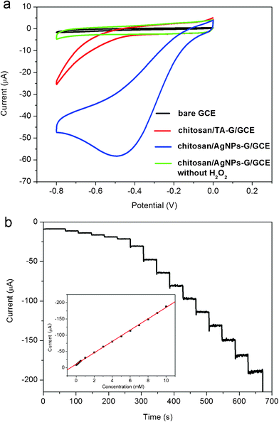 | ||
| Fig. 4 (a) Cyclic voltammograms of different electrodes in N2–saturated 0.2 M PBS at pH = 7.4 in the presence of 2 mM H2O2 (scan rate: 50 mV s−1). (b) Typical steady-state response of the chitosan/AgNPs–G/GCE to successive injection of H2O2 into the stirred N2–saturated 0.2 M PBS at pH = 7.4. Inset: the corresponding calibration curve (Applied potential: −0.3 V). | ||
Fig. 4b shows typical current-time plot of the chitosan/AgNPs–G/GCE in N2-saturated 0.2 M PBS buffer (pH = 7.4) on consecutive step change of H2O2 concentrations. Although the chitosan/AgNPs–G/GCE exhibited the biggest response signal at −0.50 V, determination of the H2O2 was carried out at −0.3 V. Such a low applied potential can ensure sufficient current response with lower background or less interference of other electroactive species in the solution.39 When an aliquot of H2O2 was dropped into the stirring PBS solution, the reduction current rose steeply to reach a stable value. The sensor could accomplish 96% of the steady state current within 2 s, indicating a fast amperometric response behavior. It is apparently seen that the steps shown in Fig. 4b are more horizontal in the region of lower concentration of H2O2 and the noises become higher with increased concentration of H2O2. Inset (Fig. 4b) shows the calibration curve of the sensor. The linear detection range is estimated to be from 1 × 10⁻⁴ M to 0.01 M (r = 0.999), and the detection limit is estimated to be 7 × 10⁻⁶ M at a signal-to-noise ratio of 3.
3.4 Glucose sensing
It is well known that diabetes mellitus is a worldwide public health problem and thus the detection of glucose in blood serum is particularly important.40 Based on the high electrocatalytic activity of chitosan/AgNPs–G/GCE toward H2O2, a glucose sensor was further developed by immobilizing GOD into chitosan/AgNPs–G nanocomposites film on a GCE surface. The sensing mechanism is that GOD can selectively catalyze the oxidation of glucose in the presence of oxygen to form H2O2, which can be electrochemically detected.41Fig. 5 shows the cyclic voltammograms of the chitosan/GOD/AgNPs–G/GCE in 0.2 M PBS solution at pH 7.4 with various concentrations of glucose in saturated O2. It is seen that a strong reduction current peak at −0.5 V is observed, which is attributed to the electrochemical reduction of O2 and H2O2. It is also found that the reduction current at negative potential increase with the increased amount of glucose in saturated O2. Fig. 5 inset shows the calibration curves to corresponding amperometric responses at −0.5 V. Good linear relationship is observed between the catalytic current and glucose concentration at ranges from 2 to 10 mM (R = 0.996) at −0.5 V. The detection limit is estimated to be 100 μM at a signal-to-noise ratio of 3. The RSD of the current response to 6 mM glucose at −0.5 V is 4.3% for 5 successive measurements. Compared to the RSD (5.2%) of the Pt nanoparticle-based glucose biosensor,42 our AgNPs–G nanocomposites-based sensor has better reproducibility.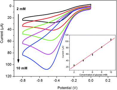 | ||
| Fig. 5 Cyclic voltammograms of chitosan/GOD/AgNPs–G/GCE in O2 saturated 0.2 M PBS at pH 7.4 in various concentrations of glucose. Inset is the calibration curves corresponding to amperometric responses at −0.5 V. | ||
Since the blood glucose levels of normal persons are in the range of 4 to 6 mM,43 our glucose biosensor may be used for glucose determination of real samples due to its wide linear response ranges. The original glucose concentration of the human blood sample is hypothesized as 5 mM. The electrolyte solution containing 1.5 mL of serum sample and 3.5 mL phosphate buffer solution (0.2 M, pH 7.4) is used for cyclic voltammetry experiments. The reduction peak current increases with successive addition of 1 mM glucose into the blood serum saturated with O2, as shown in Fig. 6. Fig. 6 inset shows that the peak currents increase linearly with increased glucose concentrations saturated with O2 (R = 0.998). The RSD of the current response to 6.5 mM glucose is 3.6% for 5 successive measurements.
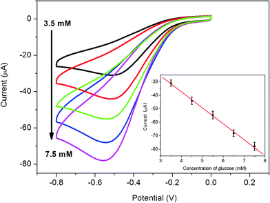 | ||
| Fig. 6 Cyclic voltammograms of chitosan/GOD/AgNPs–G/GCE in O2 saturated 1.5 mL real blood serum sample and 3.5 mL PBS solution (0.2 M, pH 7.4) in the presence of various concentrations of glucose: 3.5, 4.5, 5.5, 6.5 and 7.5 mM. Inset is the calibration curve (R = 0.998) corresponding to amperometric responses at the reduction peak (scan rate: 50 mV s−1). | ||
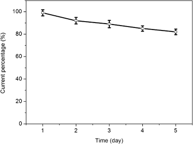
The long-term stability of the prepared glucose biosensor is a critical factor in practical detection application. To evaluate the stability of this glucose biosensor, the chitosan/GOD/AgNPs–G/GCE was stored at 4 °C. The stability was examined by periodical measurements of the biosensor responses to 2 mM glucose in PBS solution (pH 7.4) at a scan rate of 50 mV s−1. The variation of the response current at the chitosan/GOD/AgNPs–G/GCE decreases to about 92% of its initial response current on the 2nd day and about 82% on the 5th day, as shown in Fig. 7. The loss of the response current could be ascribed to the decrease of the enzyme activity during these days.
 | ||
| Fig. 7 The variation in the response current of 2 mM glucose in PBS solution (pH = 7.4) at the GOD/AgNPs–G/GCE for 5 days. Scan rate: 50 mV s−1. | ||
Conclusions
In conclusion, we have developed a facile one-pot, cost-effective method to synthesize AgNPs–G nanocomposites with the use of environmentally friendly TA as a reducing agent. The resultant AgNPs–G nanocomposites show excellent SERS activity as SERS substrates and exhibit notable catalytic performance toward H2O2 reduction. More importantly, we demonstrate successfully its application for glucose detection in both buffer and human blood serum. Our present finding is important because it provides us a green and facile one-pot method for the preparation of metal nanoparticles-G nanocomposites on a large scale for applications.Acknowledgements
This work was supported by the National Basic Research Program of China (No. 2011CB935800).References
- (a) K. S. Novoselov, S. V. Geim, S. V. Morozov, D. Jiang, Y. Zhang, S. V. Dubonos, I. V. Grigorieva and A. A. Firsov, Science, 2004, 306, 666 CrossRef CAS; (b) M. J. Allen, V. C. Tung and R. B. Kaner, Chem. Rev., 2010, 110, 132 CrossRef CAS; (c) C. N. R. Rao, A. K. Sood, K. S. Subrahmanyam and A. Govindaraj, Angew. Chem., Int. Ed., 2009, 48, 7752 CrossRef CAS.
- Y. Zhang, Y. W. Tan, H. L. Stormer and P. Kim, Nature, 2005, 438, 201 CrossRef CAS.
- Y. F. Xu, Z. B. Liu, X. L. Zhang, Y. Wang, J. G. Tian, Y. Huang, Y. F. Ma, X. Y. Zhang and Y. S. Chen, Adv. Mater., 2009, 21, 1275 CrossRef CAS.
- (a) D. H. Wang, D. Choi, J. Li, Z. G. Yang, Z. M. Nie, R. Kou, D. H. Hu, C. M. Wang, L. V. Saraf and J. Zhang, ACS Nano, 2009, 3, 907 CrossRef CAS; (b) E. Yoo, J. Kim, E. Hosono, H. S. Zhou, T. Kudo and I. Homa, Nano Lett., 2008, 8, 2277 CrossRef CAS.
- C. Shan, H. Yang, J. Song, D. Han, A. Ivaska and L. Niu, Anal. Chem., 2009, 81, 5603 CrossRef.
- (a) T. A. Land, T. Michely, R. J. Behm, J. C. Hemminger and G. Coma, Surf. Sci., 1992, 264, 261 CrossRef CAS; (b) K. S. Kim, Y. Zhao, H. Jang, S. Y. Lee, J. M. Kim, K. S. Kim, J. H. Ahn, P. Kim, J. Y. Choi and B. H. Hong, Nature, 2009, 457, 706 CrossRef CAS.
- (a) D. Li, M. B. Müller, S. Gilje, R. B. Kaner and G. G. Wallace, Nat. Nanotechnol., 2008, 3, 101 CrossRef CAS; (b) H. Wang, J. T. Robinson, X. Li and H. Dai, J. Am. Chem. Soc., 2009, 131, 9910 CrossRef CAS; (c) H. J. Shin, K. K. Kim, A. Benayad, S. M. Yoon, H. K. Park, I. S. Jung, M. H. Jin, H. K. Jeong, J. M. Kim, J. Y. Choi and Y. H. Lee, Adv. Funct. Mater., 2009, 19, 1987 CrossRef CAS; (d) S. Stankvich, D. A. Dikin, R. D. Piner, K. A. Kohlhaas, A. Kleinhammes, Y. Jia, Y. Wu, S. T. Nguyen and R. S. Ruoff, Carbon, 2007, 45, 1558 CrossRef; (e) S. Pei, J. Zhao, J. Du, W. Ren and H. M. Cheng, Carbon, 2010, 48, 4466 CrossRef CAS.
- (a) Z. Wang, X. Zhou, J. Zhang, F. Boey and H. Zhang, J. Phys. Chem. C, 2009, 113, 14071 CrossRef CAS; (b) H. Guo, X. Wang, Q. Qian, F. Wang and X. Xia, ACS Nano, 2009, 3, 2653 CrossRef CAS.
- (a) Y. Zhang, L. Guo, S. Wei, Y. He, H. Xia, Q. Chen, H. B. Sun and F. S. Xiao, Nano Today, 2010, 5, 15 CrossRef CAS; (b) G. Williams, B. Seger and P. V. Kamat, ACS Nano, 2008, 2, 1487 CrossRef CAS; (c) G. Williams and P. V. Kamat, Langmuir, 2009, 25, 13869 CrossRef CAS; (d) H. Li, S. Pang, X. Peng, K. Müllen and C. Bubeck, Chem. Commun., 2010, 46, 6243 RSC; (e) L. L. Cote, R. Cruz-silva and J. Huang, J. Am. Chem. Soc., 2009, 131, 11027 CrossRef CAS; (f) T. Wu, S. Liu, Y. Luo, W. Lu, L. Wang and X. Sun, Nanoscale, 2011, 3, 2142 RSC.
- (a) Y. Zhu, S. Murali, M. D. Stoller, A. Velamakanni, R. D. Piner and R. S. Ruoff, Carbon, 2010, 48, 2106 CrossRef; (b) W. Zhang, J. Cui, C. A. Tao, Y. Wu, Z. Li, L. Ma, Y. Wen and G. Li, Angew. Chem., Int. Ed., 2009, 48, 5864 CrossRef CAS; (c) D. V. Kosynkin, A. L. Higginbotham, A. Sinitskii, J. R. Lomeda, A. Dimiev, B. K. Price and J. M. Tour, Nature, 2009, 458, 872 CrossRef CAS; (d) L. Jiao, L. Zhang, R. Wang, G. Diankov and H. Dai, Nature, 2009, 458, 877 CrossRef CAS.
- (a) Y. Xu, H. Bai, G. Lu, C. Li and G. Q. Shi, J. Am. Chem. Soc., 2008, 130, 5856 CrossRef CAS; (b) S. Stankovich, R. D. Piner, X. Chen, N. Wu, S. T. Nguyen and R. S. Ruoff, J. Mater. Chem., 2006, 16, 155 RSC; (c) V. C. Tung, M. J. Allen, Y. Yang and R. B. Kaner, Nat. Nanotechnol., 2009, 4, 25 CrossRef CAS.
- (a) A. L. Higginbotham, D. V. Kosynkin, A. Sinitskii, Z. Sun and J. M. Tour, ACS Nano, 2010, 4, 2059 CrossRef CAS; (b) S. Liu, J. Tian, L. Wang, H. Li, Y. Zhang and X. Sun, Macromolecules, 2010, 43, 10078 CrossRef CAS; (c) X. Gao, J. Jang and S. Nagase, J. Phys. Chem. C, 2010, 114, 832 CrossRef CAS; (d) C. Shan, H. Yang, D. Han, Q. Zhang, A. Ivaska and L. Niu, Anal. Chem., 2009, 81, 2378 CrossRef CAS.
- (a) C. Zhu, S. Guo, Y. Fang and S. Dong, ACS Nano, 4, 2429 CrossRef CAS; (b) S. Liu, J. Tian, L. Wang, Y. Luo, W. Lu and X. Sun, Biosens. Bioelectron., 2011, 26, 4491 CrossRef CAS; (c) L. Q. Xu, W. J. Yang, K.-G. Neoh, E. T. Kang and G. D. Fu, Macromolecules, 2010, 43, 8336 CrossRef CAS; (d) Y. K. Kim, M.-H. Kim and D. H. Min, Chem. Commun., 2011, 47, 3195 RSC; (e) J. Liu, S. Fu, B. Yuan, Y. Li and Z. Deng, J. Am. Chem. Soc., 2010, 132, 7279 CrossRef CAS; (f) J. Zhang, H. Yang, G. Shen, P. Cheng, J. Zhang and S. Guo, Chem. Commun., 2010, 46, 1112 RSC; (g) Z. Zhang, F. G. Xu, W. S. Yang, M. Y. Guo, X. D. Wang, B. L. Zhang and J. L. Tang, Chem. Commun., 2011, 47, 6440 RSC; (h) H. Wu, J. Wang, X. H. Kang, C. M. Wang, D. H. Wang, J. Liu, I. A. Aksay and Y. H. Lin, Talanta, 2009, 80, 403 CrossRef CAS.
- (a) S. Stankovich, D. A. Dikin, G. H. B. Dommett, K. M. Kohlhaas, E. J. Zimney, E. A. Stach, R. D. Piner, S. T. Nguyen and R. S. Ruoff, Nature, 2006, 442, 282 CrossRef CAS; (b) A. C. Balazs, T. Emrick and T. P. Russell, Science, 2006, 314, 1107 CrossRef CAS; (c) N. S. Sariciftci, L. Smilowitz, A. J. Heeger and F. Wudl, Science, 1992, 258, 1474 CAS; (d) R. Bashyam and P. Zelenay, Nature, 2006, 443, 63 CrossRef CAS; (e) J. R. Capadona, O. Van Den Berg, L. A. Capadona, M. Schroeter, S. J. Rowan, D. J. Tyler and C. Weder, Nat. Nanotechnol., 2007, 2, 765 CrossRef CAS.
- (a) J. C. Meyer, A. K. Geim, M. I. Katsnelson, K. S. Novoselov, T. J. Booth and S. Roth, Nature, 2007, 446, 60 CrossRef CAS; (b) X. Zhou, X. Huang, X. Qi, S. Wu, C. Xue, F. Y. C. Boey, Q. Yan, P. Chen and H. Zhang, J. Phys. Chem. C, 2009, 113, 10842 CrossRef CAS.
- (a) J. L. Vickery, A. J. Patil and S. Mann, Adv. Mater., 2009, 21, 2180 CrossRef CAS; (b) Y. Li, W. Gao, L. Ci, C. Wang and P. M. Ajayan, Carbon, 2010, 48, 1124 CrossRef CAS; (c) E. Yoo, T. Okata, T. Akita, M. Kohyama, J. Nakamura and I. Honma, Nano Lett., 2009, 9, 2255 CrossRef CAS; (d) J. Yang, M. Heo, H. J. Lee, S. M. Park, J. Y. Kim and H. S. Shin, ACS Nano DOI:10.1021/nn203073q.
- (a) C. Xu, X. Wang and J. Zhu, J. Phys. Chem. C, 2008, 112, 19841 CrossRef CAS; (b) E. Yoo, T. Okata, T. Akita, M. Kohyama, J. Nakamura and I. Honma, Nano Lett., 2009, 9, 2255 CrossRef CAS; (c) Y. M. Li, L. H. Tang and J. H. Li, Electrochem. Commun., 2009, 11, 846 CrossRef CAS; (d) B. Serger and P. V. Kamat, J. Phys. Chem. C, 2009, 113, 7990 CrossRef; (e) C. Zhu, S. Guo, Y. Zhai and S. Dong, Langmuir, 2010, 26, 7614 CrossRef CAS.
- (a) Y. Si and E. Samulski, Chem. Mater., 2008, 20, 6792 CrossRef CAS; (b) Y. Li, X. Lv, J. Lu and J. Li, J. Phys. Chem. C, 2010, 114, 21770 CrossRef CAS.
- (a) J. Lu, I. Do, L. T. Drzal, R. M. Worden and I. Lee, ACS Nano, 2008, 2, 1825 CrossRef CAS; (b) S. Guo, D. Wen, Y. Zhai, S. Dong and E. Wang, ACS Nano, 2010, 4, 3959 CrossRef CAS; (c) S. Mao, G. H. Lu, K. H. Yu, Z. Bo and J. H. Chen, Adv. Mater., 2010, 22, 3521 CrossRef CAS; (d) G. H. Lu, K. H. Yu, L. E. Ocolab and J. H. Chen, Chem. Commun., 2011, 47, 7761 RSC.
- W. S. Hummers and R. E. Offeman, J. Am. Chem. Soc., 1958, 80, 1339 CrossRef CAS.
- Y. D. Lei, Z. H. Tang, R. J. Liao and B. C. Guo, Green Chem., 2011, 13, 1655 RSC.
- W. B. Li, Y. Y. Guo and P. Zhang, J. Phys. Chem. C, 2010, 114, 6413 CAS.
- (a) X. Huang, Y. P. Wang, X. P. Liao and B. Shi, Chem. Commun., 2009, 4687 RSC; (b) X. Huang, H. Wu, X. P. Liao and B. Shi, Green Chem., 2010, 12, 395 RSC.
- A. E. Hagerman, K. M. Riedl, G. A. Jones, K. N. Sovik, N. T. Ritchard, P. W. Hartzfeld and T. L. Riechel, J. Agric. Food Chem., 1998, 46, 1887 CrossRef CAS.
- (a) M. Zhou, Y. L. Wang, Y. M. Zhai, J. F. Zhai, W. Ren, F. A. Wang and S. J. Dong, Chem.–Eur. J., 2009, 15, 6116 CrossRef CAS; (b) Z. J. Wang, X. Z. Zhou, J. Zhang, F. Boey and H. Zhang, J. Phys. Chem. C, 2009, 113, 14071 CrossRef CAS.
- V. C. Tung, M. J. Allen, Y. Yang and R. B. Kaner, Nat. Nanotechnol., 2008, 4, 25 CrossRef.
- Y. Guo, S. Guo, J. Ren, Y. Zhai, S. Dong and E. Wang, ACS Nano, 2010, 4, 4001 CrossRef CAS.
- (a) G. I. N. Waterhouse, G. A. Bowmaker and J. B. Metson, Appl. Surf. Sci., 2001, 183, 191 CrossRef CAS; (b) D. Y. Zemlyanov, A. Nagy and R. Schlogl, Appl. Surf. Sci., 1998, 133, 171 CrossRef CAS; (c) X. Sun, S. Dong and E. Wang, Macromolecules, 2004, 37, 7105 CrossRef CAS.
- K. Kim and H. S. Lee, J. Phys. Chem. B, 2005, 109, 18929 CrossRef CAS.
- (a) G. Wei, L. Wang, Z. Liu, Y. Song, L. Sun, T. Yang and Z. Li, J. Phys. Chem. B, 2005, 109, 23941 CrossRef CAS; (b) L. Wang, H. L. Li, J. Q. Tian and X. P. Sun, ACS Appl. Mater. Interfaces, 2010, 2, 2987 CrossRef CAS.
- S. Guo, S. Dong and E. Wang, Cryst. Growth Des., 2009, 9, 372 CAS.
- Y. Fang, Y. Li, H. Xu and M. Sun, Langmuir, 2010, 26, 7737 CrossRef CAS.
- (a) S. Stankovich, R. D. Piner, X. Chen, N. Wu, S. T. Nguyen and R. S. Ruoff, J. Mater. Chem., 2006, 16, 155 RSC; (b) F. H. Li, Y. Bao, J. Chai, Q. X. Zhang, D. X. Han and L. Niu, Langmuir, 2010, 26, 12314 CrossRef CAS.
- (a) H. Q. Zhou, C. Y. Qiu, F. Yu, H. C. Yang, M. J. Chen, L. J. Hu and L. F. Sun, J. Phys. Chem. C, 2011, 115, 11348 CAS; (b) H. Q. Zhou, C. Y. Qiu, Z. Liu, H. C. Yang, L. J. Hu, J. Liu, H. F. Yang, C. Z. Gu and L. F. Sun, J. Am. Chem. Soc., 2010, 132, 944 CrossRef CAS; (c) Z. T. Luo, L. A. Somers, Y. P. Dan, T. Ly, N. J. Kybert, E. J. Mele and A. T. C. Johnson, Nano Lett., 2010, 10, 777 CrossRef CAS.
- (a) J. Lee, K. S. Novoselov and H. S. Shin, ACS Nano, 2011, 5, 608 CrossRef CAS; (b) J. Lee, S. Shim, B. Kim and H. S. Shin, Chem. Eur. J., 2011, 17, 2381 CAS.
- J. Huang, L. M. Zhang, B. Chen, N. Ji, F. H. Chen, Y. Zhang and Z. J. Zhang, Nanoscale, 2010, 2, 2733 RSC.
- C. J. Orendorff, A. Gole, T. K. Sau and C. Murphy, Anal. Chem., 2005, 77, 3261 CrossRef CAS.
- (a) K. Kim and J. K. Yoon, J. Phys. Chem. B, 2005, 109, 20731 CrossRef CAS; (b) K. Kim and H. S. Lee, J. Phys. Chem. B, 2005, 109, 18929 CrossRef CAS.
- B. Zhao, Z. Liu, Z. Liu, G. Liu, Z. Li, J. Wang and X. Dong, Electrochem. Commun., 2009, 11, 1707 CrossRef CAS.
- K. E. Toghill and R. G. Compton, Int. J. Electrochem. Sci., 2010, 5, 1246 CAS.
- (a) W. Jia, K. Wang and X. Xia, TrAC, Trends Anal. Chem., 2010, 29, 306 CrossRef CAS; (b) M. Tsai and Y. Tsai, Sens. Actuators, B, 2009, 141, 592 CrossRef.
- X. Kang, Z. Mai, X. Zou, P. Cai and J. Mo, Talanta, 2008, 74, 879 CrossRef CAS.
- C. S. Shan, H. F. Yang, D. X. Han, Q. X. Zhang, A. Ivaskab and L. Ni, Biosens. Bioelectron., 2010, 25, 1070 CrossRef CAS.
Footnote |
| † Electronic supplementary information (ESI) available: Supplementary figures. See DOI: 10.1039/c1ra00641j |
| This journal is © The Royal Society of Chemistry 2012 |