Photosensitization of ZnO rod electrodes with AgInS2 nanoparticles and ZnS-AgInS2 solid solution nanoparticles for solar cell applications
Tetsuya
Sasamura
a,
Ken-ichi
Okazaki
a,
Akihiko
Kudo
b,
Susumu
Kuwabata
cd and
Tsukasa
Torimoto
*ad
aDepartment of Crystalline Materials Science, Graduate School of Engineering, Nagoya University, Chikusa-ku, Nagoya, 464-8603, Japan. E-mail: torimoto@apchem.nagoya-u.ac.jp; Fax: +81-52-789-5299; Tel: +81-52-789-4614
bDepartment of Applied Chemistry, Faculty of Science, Tokyo University of Science, 1-3 Kagurazaka, Shinjuku-ku, 162-8601, Tokyo, Japan
cDepartment of Applied Chemistry, Graduate School of Engineering, Osaka University, Suita, 565-0870, Osaka, Japan
dJapan Science and Technology Agency, CREST, Kawaguchi, Saitama, 332-0021, Japan
First published on 15th November 2011
Abstract
Nanoparticles of a ZnS-AgInS2 solid solution (ZAIS) were successfully immobilized on the surface of ZnO nanorod electrodes without using additional cross-linking agents. Irradiation of ZAIS-immobilized ZnO rod electrodes produced an anodic photocurrent, indicating that ZAIS particles worked as a photosensitizer and that the photogenerated electrons in ZAIS were injected into the conduction band of ZnO nanorods. The magnitude of the photocurrent increased with the red shift of the absorption onset of immobilized ZAIS nanoparticles. Sandwich-type solar cells fabricated with the ZAIS-loaded ZnO nanorod electrode as a working electrode and an acetonitrile solution containing the redox couple of I−/I3− exhibited a photoresponse in the visible light region, being dependent on the chemical composition of the immobilized ZAIS particles. Action spectra of photocurrent agreed well with the diffuse reflectance spectra of the corresponding electrodes. The optimum energy conversion efficiency was 0.72% under irradiation with simulated light of AM 1.5.
1. Introduction
Optical properties of size-quantized semiconductor nanoparticles (quantum dots) can be controlled by adjusting the size and shape of nanoparticles and their chemical composition.1,2 The tunability has been attracting much attention for application of these nanoparticles to biomolecular imaging,3,4 LEDs,5,6 and solar cells.2,7 Semiconductor nanoparticles are promising materials as photosensitizers in solar cells because inorganic nanoparticles are expected to exhibit longer stabilities than those of organic dyes under irradiation and because their light absorbing properties can be controlled to effectively utilize solar light energy. Furthermore, it has recently been reported that multiple exiciton generation,7–10 which is expected to boost energy conversion efficiency of the traditional Shockley–Queisser limit11 (32%), was observed in the case of the photoexcitation of semiconductor nanoparticles with a single photon of high energy.Methods for preparing high-quality metal chalcogenide nanoparticles containing cadmium or lead, such as CdS12–15, CdSe12,16,17 or PbSe,18,19 have been established. Studies to clarify their photoelectrochemical properties and to apply these particles as light-absorbing materials for solar cells have been carried out. However the content of highly toxic elements, such as Cd and Pb, restrict the range of their use. Chalcopyrite semiconductor nanoparticles of I-III-VI2 groups that do not contain any highly toxic elements have recently become promising alternative materials because they are direct transition semiconductors exhibiting a high absorption coefficient and some of their band gap energies are located at the red edge of the solar spectrum.20,21 Various types of photovoltaic devices, such as thin film solar cells and nanoparticle-sensitized solar cells, have been developed by using colloidally synthesized nanoparticles of Cu-based I-III-VI2 semiconductors of CuInS222 and Cu(InxGa1-x)Se2.22–24 Furthermore, Quo et al. reported that ZnS-CuInS2 solid solution nanoparticles25 were useful as a photosensitizer for ZnO electrodes and that the fabrication of solar cells with the resulting electrodes enabled solar light energy conversion of 0.71%. On the other hand, Ag-based I-III-VI2 nanoparticles also exhibit intense absorption in the wavelength range from the visible to near-IR region, and they are therefore attractive materials for light absorption layers for light–electricity conversion systems. We previously reported26,27 the preparation of highly luminescent nanoparticles of a ZnS-AgInS2 solid solution (ZAIS) that exhibited a tunable energy gap depending on their composition in solid solution. Although Ag-based particles also seem to be useful for solar cell applications, there has been no report on the photoelectrochemical properties of these particles, except for our brief communication28 of a study in which ZAIS nanoparticles having only two different chemical compositions were used as photosensitizers for ZnO nanorod electrodes.
In this study, we immobilized ZAIS nanoparticles on ZnO rod electrodes of various chemical compositions and investigated the photoelectrochemical properties of ZAIS nanoparticles. We also used the thus-obtained composite electrodes for the fabrication of sandwich-type solar cells, in which ZAIS particles on ZnO rod electrodes acted as a photosensitizer.
2. Experimental
2.1 Materials
Chemicals used in the present study, including acetone, ethanol, methanol, hexamethylenetetramine, potassium sulfite, iodine, lithium iodide and acetonitrile (Kishida Reagents Chemicals), zinc acetate dihydrate, zinc nitrate hexahydrate, sodium N,N-diethyldithiocarbamate, silver nitrate, indium nitrate trihydrate, n-octylamine, chloroform, sodium sulfide nonahydrate (Wako Pure Chemical Industry), and 4-tert-butylpyridine (Tokyo Chemical Industry), were used as received. Aqueous solutions were prepared just before use with purified water by a Millipore Milli-Q system.2.2 Preparation of ZnO nanorod thin films
ZnO rod arrays were deposited according to literature procedures on a fluorine-doped SnO2 (FTO) electrode using the chemical bath deposition method.29,30 FTO substrates were cleaned by sonication in an acetone–ethanol mixture solution (1![[thin space (1/6-em)]](https://www.rsc.org/images/entities/char_2009.gif) :
:![[thin space (1/6-em)]](https://www.rsc.org/images/entities/char_2009.gif) 1) for 30 min and by UV-ozone treatment for 1 h. A portion of 0.10 mol dm−3zinc acetate methanol solution was spin-coated 8 times onto a cleaned FTO glass (2 × 4 cm; sheet resistance, 10 Ω/square) at 5000 rpm. Then the substrate was annealed in air at 350 °C for 30 min to immobilize ZnO particles as a seed crystal. The thus-obtained substrate was immersed in an aqueous solution (50 cm3) containing 25 mmol dm−3zinc nitrate and 25 mmol dm−3hexamethylenetetramine at 90 °C for 6 h to deposit ZnO rods. These deposition procedures were repeated 3 times unless otherwise specified, followed by calcination of ZnO rods electrodes (ZnO–rod/FTO) at 450 °C for 30 min.
1) for 30 min and by UV-ozone treatment for 1 h. A portion of 0.10 mol dm−3zinc acetate methanol solution was spin-coated 8 times onto a cleaned FTO glass (2 × 4 cm; sheet resistance, 10 Ω/square) at 5000 rpm. Then the substrate was annealed in air at 350 °C for 30 min to immobilize ZnO particles as a seed crystal. The thus-obtained substrate was immersed in an aqueous solution (50 cm3) containing 25 mmol dm−3zinc nitrate and 25 mmol dm−3hexamethylenetetramine at 90 °C for 6 h to deposit ZnO rods. These deposition procedures were repeated 3 times unless otherwise specified, followed by calcination of ZnO rods electrodes (ZnO–rod/FTO) at 450 °C for 30 min.
2.3 Preparation of ZAIS nanoparticles
ZAIS nanoparticles were prepared by thermal decomposition of (AgIn)xZn2(1–x)(S2CNEt2)4 powders as reported in our previous paper26 except for the use of octylamine in place of oleylamine. Fifty mg of precursor powder (x = 1.0, 0.9, 0.8, 0.6 and 0.4) was put in a test tube and heated at 180 °C for 30 min under an N2 atmosphere. After adding octylamine (3.0 cm3), the resulting suspension was heated at 180 °C for 3 min under an N2 atmosphere. The solution was subjected to centrifugation to remove large precipitates. The thus-obtained supernatant contained ZAIS nanoparticles and was used for the immobilization procedure of ZAIS nanoparticles on the ZnO surface. On the other hand, for electrochemical measurement, ZAIS nanoparticles were isolated by adding methanol to the octylamine solution and then precipitates were redispersed in chloroform. ZAIS nanoparticle-immobilized FTO electrodes were prepared by casting the ZAIS nanoparticle chloroform solution on FTO electrodes. In the present study, ZAIS nanoparticles prepared from the precursor powder of (AgIn)xZn2(1-x)(S2CNEt2)4 complex were denoted as ZAIS(x).2.4 Immobilization of ZAIS nanoparticles on ZnO rod electrodes
Electrodes of ZnO–rod/FTO (2 × 2 cm) were immersed for 24 h in an octylamine solution containing ZAIS(x) particles. After washing several times with methanol, the thus-obtained ZAIS nanoparticle-immobilized ZnO–rod/FTO electrodes, denoted in this study as ZAIS(x)/ZnO–rod/FTO, were heat-treated at 180 °C under vacuum. As reported in our previous paper,26 the content of ZnS in the ZAIS solid solution decreased with an increase in x.2.5 Characterizations
UV-visible absorption spectra of the solution were measured using a spectrophotometer (Agilent Technology 8453A). Diffuse reflectance spectra of the electrodes were recorded with a spectrophotometer (Jasco V-670) equipped with an integration sphere. Scanning electron microscope (SEM) images were obtained with a Hitachi SU-1500. The size and shape of ZAIS particles were observed with a transmission electron microscope (TEM, Hitachi H-7650) at operation voltage of 100 kV.Photoelectrochemical properties of the obtained electrodes were determined in an aqueous solution (pH 13.5) containing Na2S (0.35 mol dm−3) and K2SO3 (0.25 mol dm−3) as hole scavengers. Irradiation was performed by using a 300 W Xe lamp (USHIO X300) through a UV cut-off filter (λ > 350 nm) with light intensity of 65 mW cm−2. Electrodes of a Pt wire and an electrode of Ag/AgCl (sat.KCl) were used as counter and reference electrodes, respectively. Photocurrent–potential curves of ZAIS nanoparticle-immobilized FTO electrodes or ZnO–rod/FTO electrodes were measured using a lock-in technique; the photocurrent was detected with a potentiostat (Hokuto Denko, HA-151) and amplified with a lock-in amplifier (NF circuit, LI5640) by extracting the signal that was synchronized with irradiation. Light irradiation was carried out by chopping at 7 Hz. On the other hand, current–potential characteristics of ZAIS(x)/ZnO–rod/FTO were obtained both in the dark and under irradiation without light chopping. Action spectra of photocurrents were obtained under potential application at + 0.5 V vs.Ag/AgCl with monochromatic light irradiation extracted from a 300 W Xe lamp through a monochromator (JASCO, CT-10T). The incident photon-to-current efficiency (IPCE) was calculated by dividing the number of electrons detected in the photocurrents by that of the incident photons.
2.6 Fabrication of sandwich-type solar cells
Sandwich-type solar cells were prepared with a ZAIS(x)/ZnO–rod/FTO electrode and a Pt counter electrode. These electrodes were separated by a thin HIMILAN® film (thickness of 50 μm). The electrolyte solution was an acetonitrile solution containing I2 (0.050 mol dm−3), LiI (0.10 mol dm−3) and 4-tert-butylpyridine (0.50 mol dm−3), and it was poured into the space between the electrodes. The additive of 4-tert-butylpyridine has been reported to act as a surface-modification reagent for the removal of the surface defect sites on metal oxide particle electrodes in dye-sensitized solar cells.31 Current-potential characteristics were measured with AM1.5 irradiation using a solar simulator (Asahi spectra, HAL-320). Action spectra of photocurrents were obtained at the voltage of 0 V (short circuit condition).3. Results and discussion
3.1 Deposition of ZnO nanorods on the FTO surface
Fig. 1a and b show typical SEM images of ZnO nanorods chemically deposited on the FTO surface. The electrode surfaces were densely covered with ZnO rods in each case. The nanorods were grown with an increase in the number of deposition cycles. Fig. 1c shows the length and width of ZnO nanorods as a function of the number of deposition cycles. Both the length and width of nanorods were linearly increased with increase in deposition cycles. These results indicated that the aspect ratio of ZnO nanorods was constant at ca. 20 regardless of the number of deposition cycles, similar to the results previously reported by Greeneet al.29X-Ray diffraction analyses revealed that deposited ZnO nanorods had a hexagonal crystal structure, the c-axis of which was roughly perpendicular to the FTO surface.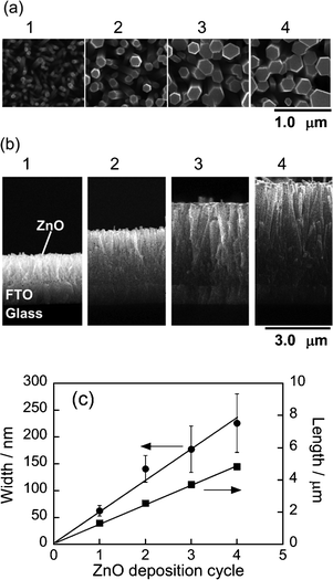 | ||
| Fig. 1 (a) Top and (b) cross-sectional view SEM images of ZnO–rod/FTO electrodes. The number of ZnO deposition cycles is indicated in the figures. (c) Dependence of rod width and length on number of ZnO deposition cycles. | ||
3.2 Characterization of ZAIS nanoparticles prepared in octylamine
Thermal decomposition of the precursor complex with x = 1.0, that is, AgIn(S2CNEt2)4, produced spherical particles of AgInS2 (ZAIS(1.0)) that were well-dispersed in the solution as shown in Fig. 2a. The X-ray powder diffraction pattern of these particles with Cu Kα radiation showed three broad peaks at 2θ = 26.7, 44.8 and 52.3°, being in good agreement with that of a tetragonal AgInS2 crystal. The size distribution obtained from TEM images was relatively broad as shown in Fig. 2b. The average size (dav) of ZAIS(1.0) nanoparticles was ca. 4.8 nm with a standard deviation (σ) of 0.6 nm. These values were similar to those reported in our previous paper26 for ZAIS(1.0) particles prepared in an oleylamine solution, which were nanoparticles of a tetragonal AgInS2 crystal structure having dav of 4.4 nm and σ of 0.8 nm.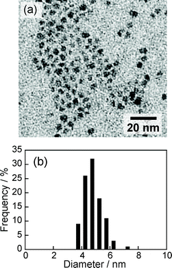 | ||
| Fig. 2 (a) Typical TEM image of ZAIS(1.0) nanoparticles. (b) Size distribution of ZAIS(1.0) nanoparticles determined from TEM images. | ||
The nanoparticles of ZAIS(1.0) exhibited photoelectrochemical activities in an aqueous solution (pH 13.5) containing Na2S and K−12SO3 as hole scavengers. Fig. 3a shows a photocurrent–potential curve of a ZAIS(1.0)-immobilized FTO electrode obtained by using a lock-in technique. An anodic photocurrent was observed at potentials more positive than −0.85 V vs.Ag/AgCl by irradiating light with a wavelength longer than 350 nm. This indicated that ZAIS(1.0) nanoparticles exhibited a photoresponse similar to that of an n-type semiconductor. The onset potential was assumed to be a flat band potential (EFB) comparable to the conduction band edge (ECB) of an n-type semiconductor. Therefore, ECB of ZAIS(1.0) was estimated to be −0.85 V vs.Ag/AgCl, which was almost the same as that of the potential of ECB reported in bulk AgInS2.32 On the other hand, ZnO–rod/FTO electrodes gave an anodic photocurrent at potential more negative than −0.7 V vs.Ag/AgCl (Fig. 3b). Since it is well known that the EFB of ZnO is shifted by −60 mV/pH, the obtained value for ZnO nanorods was an intermediate value between the potentials of ECB, −0.57 and −0.86 V vs.Ag/AgCl at pH 13.5, expected for bulk ZnO crystals exposing (1010) and (0001) facets,33 which were reported to be lateral surfaces and the top face of the ZnO rod, respectively.
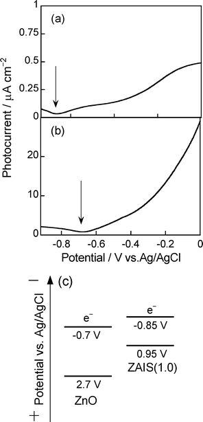 | ||
| Fig. 3 Photocurrent–potential curves of ZAIS(1.0) nanoparticles (AgInS2) (a) and ZnO rods deposited on FTO electrodes (b). ZnO rods were deposited with one deposition cycle. (c) Energy diagram of ZAIS particles and ZnO rods. | ||
Electric energy diagrams of ZAIS(1.0) particles and ZnO rods are illustrated in Fig. 3c, where the potential of the valence band edge (EVB) was estimated by subtracting the optically determined energy gaps of ZAIS(1.0) particles (1.8 eV) and the ZnO nanorod (3.4 eV) from the corresponding values of ECB. ZAIS(1.0) had an ECB sufficiently negative to inject the electrons photogenerated in ZAIS(1.0) particles into ZnO rods. It has been reported by Kudo et al.34 that the energy structure of ZAIS particles varied depending on the chemical composition of particles; ECB and EVB were shifted to more negative and positive potentials, respectively, with an increase in the content of ZnS in the solid solution particles. Since it was reported in our previous paper that the content of ZnS in ZAIS(x) particles was increased with a decrease in the value of x in the composition of precursor powders,26 we can assume that the ZAIS(x) particles in the present study have more negative ECB than that of ZnO, regardless of the composition of ZAIS particles, and that photoinduced electron transfer occurs from photoexcited ZAIS(x) particles to ZnO rods.
3.3 Absorption properties of ZAIS(x)/ZnO–rod/FTO electrodes
Fig. 4 shows absorption spectra of ZAIS(x) nanoparticles dissolved in octylamine solution and diffuse reflectance spectra of the resulting electrodes after immobilization of ZAIS(x) particles (ZAIS(x)/ZnO–rod/FTO). The absorption spectra of ZAIS(x) were blue-shifted with a decrease in the x value of ZAIS(x), accompanied by change in the onset wavelength from 700 nm to 520 nm (Fig. 4a). These results indicated that the energy gap of ZAIS(x) particles was enlarged from 1.8 to 2.4 eV with a decrease in the x value from 1.0 to 0.4, due to an increase in the content of ZnS in the ZnS–AgInS2 solid solution, being in accordance with results for particles prepared in oleylamine reported in our previous paper.26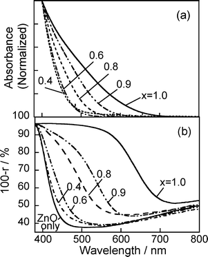 | ||
| Fig. 4 (a) Absorption spectra of ZAIS(x) particles in octylamine solutions. (b) Diffuse reflectance spectra of ZAIS(x)/ZnO–rod/FTO electrodes. ZnO rods were deposited on FTO with 3 deposition cycles. The number in the figure is the x value of ZAIS(x) used. | ||
The nanoparticles in the octylamine solution could be loaded onto the ZnO surface by immersing ZnO nanorod electrodes in the resulting solution without adding any cross-linking agents. The thus-obtained electrodes exhibited absorption in the visible wavelength region as shown in Fig. 4b. With a decrease in the x value of immobilized ZAIS(x) from 1.0 to 0.4, the reflectance spectra were blue-shifted, accompanied by a shift of the onset wavelength from 730 to 500 nm. Each absorption onset in the diffuse reflectance spectra agreed well with that in the absorption spectrum of the corresponding ZAIS(x) particles in octylamine solutions. These facts indicated that the immobilization procedure did not cause any changes in the energy gap of ZAIS particles and that the absorption properties of the ZAIS(x)/ZnO–rod/FTO electrodes were tunable depending on the chemical composition of ZAIS nanoparticles used. Fig. 5 shows pictures of ZAIS(x)/ZnO–rod electrodes after immersion in ZAIS solutions for 24 h. Though as-prepared ZnO nanorod electrodes were white, their color varied from pale yellow to dark red with an increase in the x value of ZAIS(x) from x = 0.4 to 1.0.
 | ||
| Fig. 5 Photographs of ZnO–rod/FTO(a) and ZAIS(x)/ZnO–rod/FTO (b–f) electrodes. The x values of immobilized ZAIS(x) are 0.4 (b), 0.6 (c), 0.8 (d), 0.9 (e) and 1.0 (f). | ||
It should be noted that the photoluminescence of ZAIS(x) nanoparticles was almost completely quenched after the immobilization on ZnO electrodes regardless of the x value, while the particles dissolved in chloroform exhibited intense photoluminescence under UV irradiation as previously reported for particles prepared in oleylamine,26 the peak wavelength being blue-shifted from ca. 720 to 540 nm with a decrease in x from 1.0 to 0.4. These facts indicated that the photoexcited electrons in ZAIS(x) particles were injected into the conduction band of ZnO rods, as expected by the difference in the potential of ECB between ZAIS(x) and ZnO (Fig. 3c).
3.4 Photoresponse of ZAIS(x)/ZnO–rod/FTO electrodes
Fig. 6 shows current–potential curves of ZAIS(x)/ZnO–rod/FTO electrodes in Na2S/K2SO3 solution with and without Xe lamp irradiation. Although application of potential more positive than −0.7 V vs.Ag/AgCl caused almost no current flow without irradiation, the irradiation (λ > 350 nm) produced anodic photocurrents in each case, in which the magnitude of photocurrent decreased with negative shift of the applied potential. This indicated that ZAIS(x)/ZnO–rod/FTO electrodes exhibited behavior similar to that of n-type semiconductor photoelectrodes. A larger photocurrent was observed for the ZnO–rod/FTO electrodes with ZAIS particles than without immobilization at potentials more positive than −0.6 V vs.Ag/AgCl, the degree being enhanced for ZAIS(x) particles prepared with a larger x value. Fig. 7a shows action spectra of the photocurrent measured at + 0.5 V vs.Ag/AgCl for ZAIS(x)/ZnO–rod/FTO. The observed spectra were blue-shifted with a decrease in the x value of ZAIS(x) particles used. Furthermore, the onset wavelength of action spectra was in good agreement with that of diffuse reflectance spectra of the corresponding electrode (Fig. 4b). These results indicated that ZAIS particles immobilized on ZnO nanorods worked as a visible light photosensitizer and that photogenerated electrons in ZAIS nanoparticles were injected into the conduction band of ZnO rods regardless of the x value of ZAIS particles used.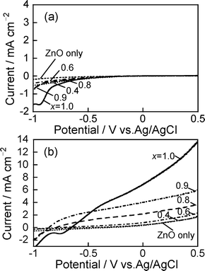 | ||
| Fig. 6 (a) Current–potential curves of ZAIS(x)/ZnO–rod/FTO obtained in the dark (a) and with Xe lamp irradiation (λ > 350 nm) (b). The number in the figure is the x value of ZAIS(x) used. | ||
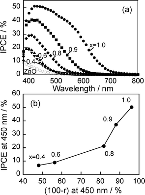 | ||
| Fig. 7 (a) Action spectra of ZAIS(x)/ZnO–rod/FTO with potential application at 0.5 V vs.Ag/AgCl. (b) Relationship between IPCE and light absorption at 450 nm. ZnO rods were deposited on FTO with 3 deposition cycles. The number in the figure is the x value of ZAIS(x) used. | ||
Fig. 7b shows the relationship between IPCE and absorption at 450 nm for ZAIS(x)/ZnO–rod/FTO electrodes. With an increase in light absorption of the electrodes, the obtained IPCE was simply enlarged. This fact indicated that the magnitude of the photocurrent was mainly determined by the amount of absorbed photons, not by the chemical composition of ZAIS(x) particles immobilized. It should be noted that IPCE values of ca. 40–50% were obtained with 450 nm light irradiation for the photoelectrodes immobilized with ZAIS(x) particles of x = 0.9 and 1.0.
3.5 Influence of length of the ZnO nanorod on photoelectrochemical properties
ZAIS(1.0) nanoparticles were immobilized on electrodes composed of ZnO rods whose length was varied from 1.3 to 4.8 μm by changing the number of ZnO deposition cycles from 1 to 4 (Fig. 1c). The diffuse reflectance spectra of ZnO nanorod electrodes after immobilization of ZAIS(1.0) particles exhibited almost the same absorption onset (Fig. 8a), suggesting that the immobilization procedure did not cause any changes in the energy gap of ZAIS(1.0) particles. On the other hand, the Kubelka–Munk function in the wavelength region between 450 and 700 nm slightly increased with an increase in the number of ZnO deposition cycles except for the case of 4 cycles, that is, with an increase in the length of ZnO rods, indicating that the larger surface area of ZnO nanorods electrodes was preferable to immobilize the larger amount of AgInS2 nanoparticles on the electrodes. The Kubelka–Munk function decreased for the film prepared with 4 deposition cycles rather than that obtained in the case of 3 cycles, probably due to the experimental error.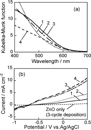 | ||
| Fig. 8 Diffuse reflectance spectra of ZAIS(1.0)/ZnO–rod/FTO electrodes (a) and their current potential curves under Xe lamp irradiation (λ > 350 nm) (b). The number in the figure represents the number of ZnO deposition cycles. | ||
Fig. 8b shows current–potential curves of ZAIS(1.0)/ZnO–rod/FTO electrodes with ZnO rods of various lengths. An anodic photocurrent was observed at potentials more positive than −0.7 V vs.Ag/AgCl and was enhanced by an increase in the number of ZnO deposition cycles, the tendency being roughly in agreement with the increase in the Kubelka–Munk function in Fig. 8a. This fact indicated that the magnitude of the photocurrent was mainly determined by the amount of absorbed photons, that is, by the amount of ZAIS(1.0) immobilized on ZnO nanorod electrodes.
3.6 Fabrication of ZAIS nanoparticle-sensitized solar cells
To evaluate the capability of our electrodes, we fabricated sandwich-type solar cells using a ZAIS(x)/ZnO–rod/FTO electrode and a Pt counter electrode. The space between the electrodes was filled with acetonitrile solution containing I−/I3−redox species. Fig. 9a shows current–potential curves of the obtained cells under AM1.5 illumination. Bare ZnO rod electrodes produced almost no photocurrent, but loading of ZAIS(x) nanoparticles onto ZnO remarkably increased the magnitude of the photocurrent, the degree being enhanced with ZAIS(x) particles with a larger x value. The action spectra of photocurrent in the short circuit condition, shown in Fig. 9b, were very similar to those of ZAIS(x)/ZnO–rod/FTO electrodes in the aqueous solution using a three-electrode configuration (Fig. 7a). This indicated that ZAIS particles worked as a photosensitizer in sandwich-type solar cells; an electron and hole pair was photogenerated in a ZAIS particle and then the electron was injected into the conduction band of ZnO with removal of the hole in ZAIS by I− in the solution. The cell fabricated with ZAIS(1.0) nanoparticles gave a maximum IPCE of 43%, indicating that efficient charge separation was achieved at the interface between ZAIS nanoparticles and ZnO rods. It should be noted that the obtained IPCE value (ca. 40%) was comparable to previously reported values for quantum dot-sensitized solar cells using nanoparticles of cadmium chalcogenide.35,36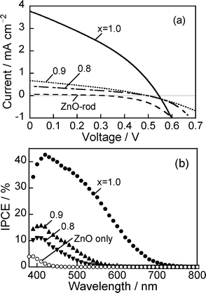 | ||
| Fig. 9 (a) Current–voltage curves of sandwich-type cells prepared with ZAIS(x)/ZnO–rod/FTO electrodes under simulated solar irradiation (AM 1.5). (b) Action spectra of photocurrent obtained at 0 V. ZnO rods were deposited on FTO with 3 deposition cycles. The number in the figure is the x value of ZAIS(x) used. | ||
Table 1 summarizes the characteristic parameters for ZAIS-sensitized solar cells obtained from Fig. 9a. Open circuit voltage (VOC) was roughly constant at ca. 0.50 V within experimental errors, even when different kinds of ZAIS(x) nanoparticles were used. Higher energy conversion efficiency (η) was obtained with immobilization of ZAIS(x) nanoparticles having a larger x value, due to an increase in the amount of absorption of irradiated photons as shown in Fig. 4b. The optimal efficiency of η was 0.72% for the electrode immobilized with ZAIS(1.0) nanoparticles, that is, AgInS2 nanoparticles. It has been reported that semiconductor nanoparticles of high toxicity, such as CdS, CdSe and PbS nanoparticles, were used as photosensitizers and loaded on porous metal oxide electrodes of TiO2 or ZnO, with the resulting quantum dot-sensitized solar cells giving η of 0.8∼4.2%.35–37 Although ZAIS-loaded ZnO nanorod electrodes gave a slightly smaller η than those reported by using conventional semiconductor nanoparticles, the low toxicity of ZAIS nanoparticles enables Ag-based I-III-VI2 semiconductor nanoparticles to be one of the promising candidates for visible light-absorbing materials for solar cells.
| ZAIS | Redox species | JSC/mA cm−2 | VOC/V | FF | η / % |
|---|---|---|---|---|---|
| none | I−/I3− | 0.06 | 0.32 | 0.37 | 0.01 |
| ZAIS(0.8) | I−/I3− | 0.44 | 0.50 | 0.31 | 0.07 |
| ZAIS(0.9) | I−/I3− | 0.67 | 0.50 | 0.31 | 0.10 |
| ZAIS(1.0) | I−/I3− | 3.8 | 0.54 | 0.35 | 0.72 |
| ZAIS(1.0) | S2−/Sx2− | 3.7 | 0.47 | 0.20 | 0.35 |
It should be noted that the sensitized solar cells fabricated with ZAIS nanoparticles worked well in the present study by using the redox couple of I−/I3− rather than polysulfide of S2−/Sx2− as shown in Table 1. This tendency was opposite to that reported for semiconductor nanoparticles of II-VI groups, in which the redox couple of I−/I3−, exhibiting ideal kinetic properties in regeneration of oxidized ruthenium dyes,38 could not work for scavenging photogenerated holes in CdS and CdSe nanoparticles used as light absorbers in the sensitized solar cells, resulting in rapid photocorrosion under irradiation.39–41 The observed difference might be due to the prevention of photocorrosion of the semiconductor by the strong adsorption of I− on Ag-based I-III-VI2 nanoparticles.
4. Conclusion
Solid solution nanoparticles of ZAIS, which worked as a photosensitizer, were successfully immobilized on the surface of ZnO nanorod electrodes without using additional cross-linking agents. Irradiation of thus-obtained electrodes produced an anodic photocurrent, the magnitude of which was increased with the red shift of the absorption onset of immobilized ZAIS nanoparticles. Sandwich-type solar cells were fabricated with ZAIS-loaded ZnO nanorod electrodes and an acetonitrile solution containing the redox couple of I−/I3−. The photoresponse of the obtained cells was tunable in a wide wavelength range of the visible light region, depending on the composition of ZAIS particles used, and the optimum energy conversion efficiency was 0.72% when ZAIS particles prepared with x = 1.0 were used. The obtained conversion efficiency was slightly smaller than the conversion efficiencies obtained by using conventional semiconductor nanoparticles such as CdS, CdSe and PbS, but photoactivity of immobilized ZAIS particles can probably be improved by appropriate selection of redox couples in the solution and/or porous metal oxide electrodes. The low toxicity of Ag-based I-III-VI2 semiconductor nanoparticles offers an advantage for practical applications of the resulting devices.Acknowledgements
This work was supported by a Grant-in-Aid for Scientific Research (A) (No. 20245031) and a Funding Program for Next Generation World-Leading Researchers from the Japan Society for the Promotion of Science and by a Grant-in-Aid for Scientific Research on Priority Areas “Strong Photon-Molecule Coupling Fields (No. 470)” (No. 19049009) from the Ministry of Education, Culture, Sports, Science and Technology of Japan. T.S. expresses his appreciation to The Global COE (Center Of Excellence) Program “Elucidation and Design of Materials and Molecular Functions” of Nagoya University.References
- A. J. Nozik, Annu. Rev. Phys. Chem., 2001, 52, 193 CrossRef CAS.
- P. V. Kamat, J. Phys. Chem. C, 2007, 111, 2834 CAS.
- H. Mattoussi, J. M. Mauro, E. R. Goldman, G. P. Anderson, V. C. Sundar, F. V. Mikulec and M. G. Bawendi, J. Am. Chem. Soc., 2000, 122, 12142 CrossRef CAS.
- M. Y. Han, X. H. Gao, J. Z. Su and S. Nie, Nat. Biotechnol., 2001, 19, 631 CrossRef CAS.
- V. L. Colvin, M. C. Schlamp and A. P. Alivisatos, Nature, 1994, 370, 354 CrossRef CAS.
- B. O. Dabbousi, M. G. Bawendi, O. Onitsuka and M. F. Rubner, Appl. Phys. Lett., 1995, 66, 1316 CrossRef CAS.
- A. J. Nozik, Phys. E., 2002, 14, 115 CrossRef CAS.
- R. D. Schaller and V. I. Klimov, Phys. Rev. Lett., 2004, 92 Search PubMed.
- R. J. Ellingson, M. C. Beard, J. C. Johnson, P. R. Yu, O. I. Micic, A. J. Nozik, A. Shabaev and A. L. Efros, Nano Lett., 2005, 5, 865 CrossRef CAS.
- J. B. Sambur, T. Novet and B. A. Parkinson, Science, 2010, 330, 63 CrossRef CAS.
- W. Shockley and H. J. Queisser, J. Appl. Phys., 1961, 32, 510 CrossRef CAS.
- K. Okazaki, N. Kojima, Y. Tachibana, S. Kuwabata and T. Torimoto, Chem. Lett., 2007, 36, 712 CrossRef CAS.
- Y. Nosaka, J. Phys. Chem., 1991, 95, 5054 CrossRef CAS.
- K. R. Gopidas, M. Bohorquez and P. V. Kamat, J. Phys. Chem., 1990, 94, 6435 CrossRef CAS.
- T. Toyoda, J. Sato and Q. Shen, Rev. Sci. Instrum., 2003, 74, 297 CrossRef CAS.
- T. Toyoda, D. Arae and Q. Shen, Jpn. J. Appl. Phys., 2005, 44, 4465 CrossRef CAS.
- I. Mora-Sero, J. Bisquert, T. Dittrich, A. Belaidi, A. S. Susha and A. L. Rogach, J. Phys. Chem. C, 2007, 111, 14889 CAS.
- J. M. Luther, M. Law, Q. Song, C. L. Perkins, M. C. Beard and A. J. Nozik, ACS Nano, 2008, 2, 271 CrossRef CAS.
- J. J. Choi, Y. F. Lim, M. B. Santiago-Berrios, M. Oh, B. R. Hyun, L. F. Sung, A. C. Bartnik, A. Goedhart, G. G. Malliaras, H. D. Abruna, F. W. Wise and T. Hanrath, Nano Lett., 2009, 9, 3749 CrossRef CAS.
- J. E. Jaffe and A. Zunger, Phys. Rev. B, 1984, 29, 1882 CrossRef CAS.
- S. Ikeda, R. Kamai, T. Yagi and M. Matsumura, J. Electrochem. Soc., 2010, 157, B99 CrossRef CAS.
- M. G. Panthani, V. Akhavan, B. Goodfellow, J. P. Schmidtke, L. Dunn, A. Dodabalapur, P. F. Barbara and B. A. Korgel, J. Am. Chem. Soc., 2008, 130, 16770 CrossRef CAS.
- Q. Guo, S. J. Kim, M. Kar, W. N. Shafarman, R. W. Birkmire, E. A. Stach, R. Agrawal and H. W. Hillhouse, Nano Lett., 2008, 8, 2982 CrossRef CAS.
- Q. Guo, G. M. Ford, H. W. Hillhouse and R. Agrawal, Nano Lett., 2009, 9, 3060 CrossRef CAS.
- K. T. Kuo, D. M. Liu, S. Y. Chen and C. C. Lin, J. Mater. Chem., 2009, 19, 6780 RSC.
- T. Torimoto, T. Adachi, K. Okazaki, M. Sakuraoka, T. Shibayama, B. Ohtani, A. Kudo and S. Kuwabata, J. Am. Chem. Soc., 2007, 129, 12388 CrossRef CAS.
- T. Torimoto, S. Ogawa, T. Adachi, T. Kameyama, K. Okazaki, T. Shibayama, A. Kudo and S. Kuwabata, Chem. Commun., 2010, 46, 2082 RSC.
- T. Sasamura, K. Okazaki, R. Tsunoda, A. Kudo, S. Kuwabata and T. Torimoto, Chem. Lett., 2010, 39, 619 CrossRef CAS.
- L. E. Greene, M. Law, J. Goldberger, F. Kim, J. C. Johnson, Y. F. Zhang, R. J. Saykally and P. D. Yang, Angew. Chem., Int. Ed., 2003, 42, 3031 CrossRef CAS.
- Y. J. Lee, T. L. Sounart, D. A. Scrymgeour, J. A. Voigt and J. W. P. Hsu, J. Cryst. Growth, 2007, 304, 80 CrossRef CAS.
- M. K. Nazeeruddin, A. Kay, I. Rodicio, R. Humphry-Baker, E. Müller, P. Liska, N. Vlachopoulos and M. Grätzel, J. Am. Chem. Soc., 1993, 115, 6382 CrossRef CAS.
- W. S. Chang, C. C. Wu, M. S. Jeng, K. W. Cheng, C. M. Huang and T. C. Lee, Mater. Chem. Phys., 2010, 120, 307 CrossRef CAS.
- W. Jaegermann, Modern aspects of electrochemistry, Plenum press, New York, 1996 Search PubMed.
- I. Tsuji, H. Kato, H. Kobayashi and A. Kudo, J. Am. Chem. Soc., 2004, 126, 13406 CrossRef CAS.
- Y. L. Lee and Y. S. Lo, Adv. Funct. Mater., 2009, 19, 604 CrossRef.
- V. Gonzalez-Pedro, X. Xu, I. Mora-Sero and J. Bisquert, ACS Nano, 2010, 4, 5783 CrossRef CAS.
- H. Lee, H. C. Leventis, S. J. Moon, P. Chen, S. Ito, S. A. Haque, T. Torres, F. Nuesch, T. Geiger, S. M. Zakeeruddin, M. Gratzel and M. K. Nazeeruddin, Adv. Funct. Mater., 2009, 19, 2735 CrossRef CAS.
- M. Gratzel, J. Photochem. Photobiol., C, 2003, 4, 145 CrossRef CAS.
- Y. Tachibana, H. Y. Akiyama, Y. Ohtsuka, T. Torimoto and S. Kuwabata, Chem. Lett., 2007, 36, 88 CrossRef CAS.
- K. S. Leschkies, R. Divakar, J. Basu, E. Enache-Pommer, J. E. Boercker, C. B. Carter, U. R. Kortshagen, D. J. Norris and E. S. Aydil, Nano Lett., 2007, 7, 1793 CrossRef CAS.
- H. J. Lee, P. Chen, S. J. Moon, F. Sauvage, K. Sivula, T. Bessho, D. R. Gamelin, P. Comte, S. M. Zakeeruddin, S. I. Seok, M. Gratzel and M. K. Nazeeruddin, Langmuir, 2009, 25, 7602 CrossRef CAS.
| This journal is © The Royal Society of Chemistry 2012 |
