DOI:
10.1039/C2PY00611A
(Paper)
Polym. Chem., 2012,
3, 1202-1214
Properties and degradation of hydrocarbon fuel cell membranes: a comparative study of sulfonated poly(arylene ether sulfone)s with different positions of the acid groups†
Received
23rd December 2011
, Accepted 6th February 2012
First published on 5th March 2012
Abstract
Sulfonated fully aromatic polymers with different positions of the acid groups, but with an identical polymer backbone, have been investigated and compared with respect to their properties as proton-exchange membranes. Three different series of sulfonated poly(arylene ether sulfone)s (SPAES) having the same backbone structure were prepared from 4,4′-dichlorodiphenyl sulfone (DCDPS) and 4,4′-dihydroxybiphenyl (BP), each series comprising three levels of the ion exchange capacity (IEC). The first series of SPAES had the sulfonic acid groups placed in ortho positions to the ether bridges (oeSPAES) and were prepared through post-polymerization sulfonation. The second and third series of SPAES carried the sulfonic acid groups in meta (msSPAES) and ortho (osSPAES) positions to the sulfone bridges, respectively, and were prepared by polycondensations of mixtures of BP, DCDPS and either 3,3′-disulfonated or 2,2′-disulfonated DCDPS, respectively. The latter monomer was synthesized via lithiation–sulfination–oxidation of DCDPS. Analysis of solvent cast membranes showed that the osSPAES copolymers had a high dimensional stability in water up to 100 °C, even at high ionic contents. Moreover, the osSPAES and the msSPAES membranes were better at retaining conductivity at reduced relative humidity than the oeSPAES membranes. Thermogravimetry of the membranes in the acid form under air indicated no significant differences based on the placement of the sulfonic acid groups. The resistance towards radical attack was analyzed by 1H NMR spectroscopy after immersing the membranes in Fenton's reagent at 60 °C, and the ability to retain IEC was found to increase in the order oeSPAES < msSPAES < osSPAES. Membrane stability was also studied in an accelerated hydrolysis test by immersing the membranes in 0.1 M aq. HCl at 200 °C in a sealed vessel. The results showed a dramatic loss of sulfonic acid in the oeSPAES membranes, presumably activated by the proximity of the ether bridges. Careful 1H NMR analysis also suggested that the osSPAES polymers degraded by scission of the sulfone bridges. The position of the sulfonic acid groups ortho to the sulfone bridges seemingly destabilized the latter under the severe conditions employed in the test.
1. Introduction
Sulfonated aromatic polymers are currently intensively investigated as membranes for reverse osmosis for production of drinking water,1 vanadium redox flow batteries for energy storage,2 and fuel cells for energy conversion.3 Polymer electrolyte membrane fuel cells (PEMFCs) combine high fuel utilization efficiency with environmentally clean operation.4,5 The characteristics of the polymer membrane, including the proton conductivity, water uptake, and thermal, chemical and mechanical stability, are central to the fuel cell performance. State-of-the-art perfluorosulfonic acid (PFSA) membranes such as Nafion® are the most widely employed membrane materials in fuel cell applications because of their high proton conductivity and chemical stability. Still, PFSA membranes typically show limitations such as high cost, high fuel crossover, restricted temperature and humidity ranges which hinder a widespread use in PEMFCs.6–8 This has motivated an intensive research over the past decade for alternative membrane materials based on various high-performance aromatic polymers functionalized with sulfonic acid groups.9–12 Despite these efforts, the performance of most aromatic membranes is still inferior to that of the PFSA membranes, especially in terms of membrane stability and conductivity at low relative humidity (RH). Sulfonated derivatives of aromatic polymers generally have a significantly lower stability than the non-sulfonated ones, and the weakest link in the former polymers is most often the bond between the polymer backbone and the sulfonic acid units. Consequently, sulfonated aromatic polymers are in general sensible towards desulfonation reactions which may lead to severe loss of conductivity and performance during prolonged operation at high temperatures.13 Thus, a systematic understanding of the relationship between polymer structure and critical membrane properties is essential for further improvements of these materials. Typical structural parameters include acidity, number and position of acidic groups and the nature of the hydrophilic and hydrophobic sequences along the polymer backbone chain.
The most widely studied aromatic polymer membrane materials include sulfonated derivatives of poly(arylene ether)s, poly(arylene ether sulfone)s (SPAES), poly(arylene ether ketone)s (SPAEK), poly(arylene sulfide sulfone)s, polyimides and polyphenylenes.9,11 Numerous polymers with various chain architectures and distributions of the sulfonic acid units have been prepared and studied in order to improve especially the stability and the conductivity at low RH. Sulfonated polymers such as SPAES and SPAEK are often prepared by using sulfonating agents such as fuming sulfuric acid. Although this is a seemingly straight-forward reaction, the conditions need to be carefully controlled in order to avoid side reactions leading to crosslinking or chain scission.14 Furthermore, the acid groups are introduced in ortho positions to the electron-donating ether bridges in the backbone, which may activate desulfonation reactions during fuel cell operation. In order to improve the control over the polymer structure and the distribution and number of acid groups, SPAES and SPAEK are now increasingly prepared by using pre-sulfonated monomers in various polycondensation reactions. For example, 3,3′-disulfonated 4,4′-dichlorodiphenylsulfone (DCDPS) has been extensively employed in polycondensations with a precisely controlled monomeric stoichiometry to prepare SPAES with both statistical and segmented structures.15,16 A further advantage is that the sulfonic acid groups are placed in meta positions to the electron-withdrawing sulfone bridges in the backbone which is expected to impede desulfonation reactions. We have previously used lithiation chemistry to introduce sulfonic acid groups in ortho sulfone positions of both block17,18 and statistical19 copolymers in post-polymerization modifications. Kreuer et al. have used 3,3′-disulfonated 4,4′-difluorodiphenylsulfone to prepare sulfonated poly(p-phenylene sulfone)s with only sulfone bridges connecting the phenyl rings in the backbone.20,21 These polymers were found to have very high thermal, thermoxidative and hydrolytic stability in comparison to other sulfonated aromatic polymers, indicating the importance of the position of the sulfonic acid group for the polymer stability.
Given the extensive research for alternative membranes based on aromatic polymers, there are surprisingly a few studies of how the membrane performance and stability are influenced by the positions of the sulfonic acid groups.22–25 In the present paper, we report on the results of a systematic study of the performance and degradation of three series of fully aromatic SPAESs with identical polymer backbone structure, but with different positions of the sulfonic acid groups. The backbone chosen for the study is archetypal for sulfonated polymers, and is identical to “polyphenylsulfone” commercially available as Radel® PPSU by Solvay. In the present work, the sulfonic acid groups were introduced in the different positions shown in Scheme 1. The first series of SPAES carried the sulfonic acid groups in ortho positions to the ether bridges (oeSPAES) and were prepared through post-polymerization sulfonation of Radel® PPSU. The second and third series of SPAES were prepared by statistical polycondensations involving 3,3′-disulfonated and 2,2′-disulfonated DCDPS, respectively. This produced SPAESs which carried the sulfonic acid groups in meta (msSPAES) and ortho (osSPAES) positions to the sulfone bridges, respectively. 2,2′-Disulfonated DCDPS is a novel monomer which was synthesized using an organolithium approach. The ion-exchange capacity (IEC) was kept at three levels in each of the three series. The polymers were investigated and compared on the basis of their water uptake, proton conductivity, thermal stability, oxidative stability (as probed by Fenton's test), and thermohydrolytic stability with a special focus on identifying differences related to the positions of the sulfonic acid groups.
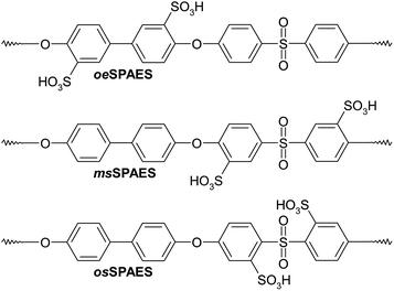 |
| | Scheme 1 SPAESs with different positions of the sulfonic acid groups along the polymer backbone, including post-sulfonated polymers with the sulfonic acid groups placed in ortho positions to the ether bridges (oeSPAES), statistical copolymers with the sulfonic acid groups placed in meta positions to the sulfone bridges (msSPAES) and statistical copolymers with the sulfonic acid groups placed in ortho positions to the sulfone bridges (osSPAES). Notably, the latter two copolymers contain statistically distributed disulfonated diarylsulfone units, while the former contains both mono- and disulfonated diarylether units. | |
2. Experimental
2.1. Materials
4,4′-Dichlorodiphenylsulfone (DCDPS, Acros, 97%) and 4,4′-dihydroxybiphenyl (BP, Acros, 97%) were recrystallized from toluene and 2-propanol, respectively. N,N-Dimethylacetamide (DMAc, Acros, 99%), toluene (Fisher Scientific, HPLC grade), 2-propanol (Fisher Scientific, HPLC grade), hydrogen peroxide (Acros, 35% solution in water), iron(II) chloride tetrahydrate (FeCl2, Sigma-Aldrich, 99%), oxalic acid (Sigma-Aldrich, 99+%, anhydrous), hydrochloric acid (Fisher Scientific, ∼36%), sodium hydroxide (Acros, extra-pure), sodium chloride (Acros, 99.5%), n-butyl lithium (n-BuLi, in hexanes, Acros, 2.5 M), sulfur dioxide (Sigma-Aldrich, 99.9%) and calcium chloride (Acros, 96%, anhydrous) were all used as received. Potassium carbonate (Acros, 99+%) was dried at 120 °C overnight. Tetrahydrofuran (THF, Fisher Scientific, analytical reagent grade) was dried with molecular sieves which had first been dried at 200 °C, and then further dried at room temperature in a vacuum oven overnight.
2.2 Synthesis of osSDCDPS
The disulfonated monomer osSDCDPS was prepared by using a lithiation–sulfination–oxidation procedure, as shown in Scheme 2. DCDPS (5.0 g, 17.4 mmol) was first dissolved in THF (100 mL) at room temperature in a reactor fitted with a gas inlet/outlet, a SO2 gas tube/inlet, a thermometer and a septum. The solution was cooled to −70 °C using a dry-ice/2-propanol bath. Subsequently, the solution was carefully degassed, before slowly adding the n-BuLi solution (15.0 mL, 37.5 mmol). After 1 h, SO2 gas was quickly introduced and the solution instantly became bright yellow before the sulfinated product precipitated. The mixture was first kept at −70 °C for 30 min and was then allowed to slowly heat up to room temperature. The yellow powder was collected by filtration and was carefully dried on the glass filter. In order to avoid decomposition of the lithium sulfinate groups, the powder was first dried on the filter and then immediately placed in a mixture of the H2O2 solution (11 mL) and water (77 mL), and kept at 40 °C overnight. After boiling at 110 °C for 30 min to quench the remaining radicals from H2O2, the mixture was filtered to remove insoluble residues. Next, the product was precipitated out in boiling water by adding NaCl. The crude monomer was finally purified by three-fold re-crystallizations from water/2-propanol (ca. 1/4 vol/vol) mixtures (yield: 3.2 g, 37%).
 |
| | Scheme 2 Synthetic pathway to the osSDCDPS monomer via lithiation, sulfination and oxidation. | |
2.3. Synthesis of sulfonated polymers
The three series of sulfonated polymers prepared in the present study were designated as aSPAESb, where a denoted the position of the sulfonate groups (os, ms, or oe), as seen in Scheme 1, and b denoted the level of sulfonation: l = low, m = medium, h = high.
The osSPAES copolymers, with sulfonic acid groups in ortho positions to the sulfone bridges, were prepared via K2CO3-mediated polycondensations of mixtures of DCDPS, osSDCDPS and BP, as shown in Scheme 3. Here, the synthesis of copolymer oeSPAESl is described. First, DCDPS (0.5057 g, 1.7611 mmol), osSDCDPS (0.2447 g, 0.4900 mmol), biphenol (0.4192 g, 2.2511 mmol), K2CO3 (0.37 g, 2.7 mmol), DMAc (5.0 mL) and toluene (5.0 mL) were placed in a two-neck flask (50 mL) equipped with a magnetic stirrer, a N2 inlet, a Dean–Stark trap filled with toluene, and a condenser fitted with a CaCl2 cartridge. The mixture was then heated to 160 °C for 4 h for dehydration and removal of the toluene. Next, the temperature was increased to 175 °C for 24 h to complete the polycondensation, before the product was precipitated in 2-propanol and washed in deionized water. The product was finally filtered off and dried at 60 °C in a vacuum oven for 24 h (yield: 0.85 g, 85%).
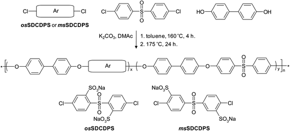 |
| | Scheme 3 Synthesis of osSPAES and msSPAES copolymers via K2CO3-mediated polycondensations involving osSDCDPS and msSDCDPS, respectively. | |
The series of copolymers with sulfonic acid groups in meta positions to the sulfone bridges (msSPAES) were prepared using msSDCDPS in a similar procedure as the one described above for the osSPAES copolymers (Scheme 3). The oeSPAES polymers were prepared by post-polymerization sulfonation of the electron-rich biphenol residues of a commercially available Radel® PAES. The level of sulfonation was controlled by the charged amount of the sulfonating agent.26–28 The details of the synthetic procedures and the characterization of the oeSPAES and the msSPAES copolymers are described in the ESI†.
2.4. Polymer characterization and membrane preparation
All monomers and copolymers prepared in the present work were characterized by 1H NMR spectroscopy by collecting data with a Bruker DRX400 spectrometer at 400.13 MHz using CDCl3 (δ = 7.28 ppm) or DMSO-d6 (δ = 2.50 ppm) solutions of the samples. The intrinsic viscosity ([η]) of the copolymers was measured with an Ubbelohde viscometer at 25 °C, using DMSO solutions containing 0.05 M LiBr and polymer in the concentration range 0.1–1.0 g dL−1.
Proton-exchange membranes were prepared by first dissolving the sulfonated polymers in DMSO (5 wt%). Then, the solutions were spread onto glass plates which had been cleaned by treatment with H2SO4/H2O2 (50 vol/vol%). Membranes with a thickness of ca. 50 μm in the dry state were cast at 80 °C for 1 day. They were detached from the glass plates after immersion in deionized water, and subsequently acidified by immersion in 1 M aq. HCl at 80 °C for 1 day, followed by repeated rinsing and washing with deionized water until a neutral pH was obtained.
2.5. Characterization of membrane IEC, water uptake and proton conductivity
The mass-based IEC (meq. g−1) value of the polymers was determined by acid–base titrations after immersing the acidified membranes in deionized water. The water uptake (WU, wt%) of the membranes was calculated from the weight-increase of the membrane after soaking in deionized water for 1 day. The hydration number (λ), i.e., the number of water molecules per sulfonic acid group, was calculated by combining the water uptake data and the IEC values. The water uptake of all membranes was measured at room temperature. Membranes were placed in deionized water and the temperature was increased from 20 to 100 °C at 20 °C increments to investigate the temperature dependence. With the weights of the dry (W) and the wet (W′) membranes, the water uptake and λ value were calculated as:| |  | (1) |
| |  | (2) |
As suggested by Kim and Pivovar,29 a transition to volume-based parameters is useful for a more detailed understanding of the characteristics of fuel cell membranes. Therefore, the volume-based IEC (IECv, meq. cm−3) was calculated from the water volume fraction (WF) of the hydrated membranes:| |  | (3) |
where r is the ratio between the partial molar volume of the polymer (Vp, cm3 mol−1), and the partial molar volume of water (Vw, cm3 mol−1):| |  | (4) |
| |  | (5) |
| |  | (6) |
ρp (g cm−3) and ρw (g cm−3) are the densities of the polymer and water, respectively. The value of ρp of SPAES was estimated by using previously published data on the correlation between the IEC and the density.30 The value of ρw varied slightly with the temperature, and 0.996 (20 °C), 0.990 (40 °C), 0.981 (60 °C), 0.969 (80 °C) and 0.955 g cm−3 (100 °C) were used in this study. Finally, IECv was calculated as:| | | IECv = IEC × ρp × (1 − WF). | (7) |
The proton conductivity (σ, S cm−1) of fully immersed membranes was measured in a sealed cell between −20 and 100 °C using a Novocontrol high resolution dielectric analyzer V 1.01S in the frequency range 101 to 107 Hz at 50 mV voltage amplitude. A two-probe method was used with the membranes preconditioned in deionized water at room temperature overnight. In order to investigate the influence of the water content on the conductivity, in other words the contribution of the water to the proton conductivity, the proton conductivity in the water channels (σ′, S cm−1) was calculated as:
| |  | (8) |
The effective proton mobility (
μ, cm
2 s
−1 V
−1) indicates an effective mobility including the uncertainties of the activity coefficient of the protons:
31,32| |  | (9) |
Here
F is Faraday's constant (9.6485 × 10
4 C mol
−1) and the proton concentration in the wet membrane [H
+] (mol cm
−3) was calculated as:
| |  | (10) |
The humidity dependence of the proton conductivity from 30 to 90% RH at 80 °C was investigated by a four-probe method, using a Gamry Potentiostat/Galvanostat/ZRA between 10−1 and 105 Hz in combination with a Fumatech® MK3 conductivity cell where the humidity was equilibrated with deionized water in a closed system. After immersion of the membranes (H+ form) in deionized water, the samples were sandwiched between tissue paper overnight before measurement in order to avoid wrinkling.
2.6. Study of membrane degradation
The thermal stability was investigated by thermogravimetric analysis (TGA) from 50 to 600 °C using a Q500 analyzer from TA Instruments. Before collecting the TGA data, the samples were pre-heated at 150 °C for 10 min to remove residual water. Membranes in the H+ form were analyzed at a heating rate of 1 °C min−1 under the air to study the oxidative degradation, while those in the Na+ form were analyzed at 10 °C min−1 under N2 to study the degradation under inert atmosphere. The degradation temperature (Td) was noted at 5% weight loss.
Fenton's reagent (a solution of H2O2 and ferrous iron catalyst) was employed to study the oxidation resistance of the membranes. Membranes in the H+ form were pre-treated by immersion in aq. H2O2 (3.5 wt%) at 60 °C for 30 min. Then, they were immersed in 1 M aq. HCl and washed in deionized water. The initial weights of the membranes were measured after drying under vacuum at 60 °C for 2 h. Next, the membranes were again placed in the aq. H2O2 at 60 °C. The test was started by adding aq. FeCl2 to give 3 ppm of Fe(II) ions in the solutions. The treatment in Fenton's reagent was stopped after a certain time by immersing the membranes in 1 M aq. HCl, followed by a wash with deionized water and final drying under vacuum at 60 °C for 2 h. The dry membranes were weighed and analyzed by 1H NMR spectroscopy. The treatment and measurements were repeated until the membranes became too brittle or soluble in Fenton's reagent.
An accelerated hydrolysis test of the membranes was performed in 0.1 M aq. HCl solution at 200 °C using a pressure-resistant autoclave. A piece of each membrane was placed in 3 mL of the HCl solution in a 10 mL Teflon® container inside the autoclave. The test was stopped after 12, 24 or 48 h. Most of the membranes became water soluble after the high-temperature treatment. Therefore, the water was evaporated from all the samples, followed by analysis of the degraded polymers by 1H NMR spectroscopy.
3. Results and discussion
3.1. Monomer synthesis
Two different disulfonated monomers based on DCDPS were synthesized and polymerized in the present work. msSDCDPS was prepared by electrophilic substitution using fuming sulfuric acid, which introduced the sulfonic acid groups in meta positions to the sulfone bridge. In addition, osSDCDPS was prepared by the lithiation–sulfination–oxidation procedure shown in Scheme 2, which introduced two sulfonic acid groups in ortho positions to the sulfone bridge. While msSDCDPS has been widely used in polycondensations to prepare various polysulfones,9–12 the synthesis and polymerizability of the novel monomer osSDCDPS for preparation of SPAESs have not been reported until now. The procedure to sulfonate the DCDPS was essentially the same as that previously employed to prepare sulfonated monomers23 and SPAES.33 The chlorine atoms of DCDPS are highly activated for nucleophilic aromatic substitution, and there was thus a potential risk that they may be substituted by n-BuLi in the lithiation step. However, the chlorine atoms were found to be stable as long as less than about 2 mol of n-BuLi was used for every mol of sulfone bridge in the reactions. Yet, in order to ensure the formation of disulfonated products, a slight excess of n-BuLi was needed and the molar ratio between n-BuLi and DCDPS was kept at 2.15![[thin space (1/6-em)]](https://www.rsc.org/images/entities/char_2009.gif) :
:![[thin space (1/6-em)]](https://www.rsc.org/images/entities/char_2009.gif) 1.00. After the sulfination and salt out of the product, small amounts of insoluble byproducts were readily removed by filtration and recrystallization in water/2-propanol. Fig. 1 shows the 1H NMR spectra of osSDCDPS and msSDCDPS. As seen, no resonance signals above 8 ppm were observed in the spectrum of osSDCDPS. Signal a, arising from the protons in-between the sulfonic acid group and the chlorine atom, appeared at 7.6–7.7 ppm and overlapped with signal b. The spectrum of msSDCDPS showed a signal a at 8.3–8.4 ppm, corresponding to the protons between the sulfone bridge and the sulfonic acid group. The integrals of the signals were in excellent agreement with the two target structures and no unknown signals were observed.
1.00. After the sulfination and salt out of the product, small amounts of insoluble byproducts were readily removed by filtration and recrystallization in water/2-propanol. Fig. 1 shows the 1H NMR spectra of osSDCDPS and msSDCDPS. As seen, no resonance signals above 8 ppm were observed in the spectrum of osSDCDPS. Signal a, arising from the protons in-between the sulfonic acid group and the chlorine atom, appeared at 7.6–7.7 ppm and overlapped with signal b. The spectrum of msSDCDPS showed a signal a at 8.3–8.4 ppm, corresponding to the protons between the sulfone bridge and the sulfonic acid group. The integrals of the signals were in excellent agreement with the two target structures and no unknown signals were observed.
 |
| | Fig. 1
1H NMR spectra of (a) osSDCDPS and (b) msSDCDPS, recorded using DMSO-d6 solutions. | |
3.2. Preparation of sulfonated polymers
Three series of sulfonated copolymers with different positions of the sulfonic acid groups, but with an identical backbone polymer structure, were prepared (Scheme 1). Each series was composed of copolymers with three different levels of the IEC. The msSPAES and osSPAES series were prepared in accordance with Scheme 3 by copolymerizations using msSDCDPS and osSDCDPS, respectively. The oeSPAES series, on the other hand, was obtained via mild sulfonations of a commercially available Radel® PPSU. The data of the different polymers are collected in Table 1.
Table 1 Sulfonated copolymer data
|
|
IECtargeta/meq. g−1 |
IECNMRb/meq. g−1 |
IECtitr.c/meq. g−1 |
[η]d/dL g−1 |
T
d (H+)e/°C |
T
d (Na+)f/°C |
|
From feed stoichiometry.
Determined by 1H NMR.
Determined by titration.
Measured in DMSO containing 0.05 M LiBr at 25 °C.
Measured under air in the H+ form.
Measured under N2 in the Na+ form.
|
|
oeSPAESl |
1.70 |
1.32 |
1.24 |
0.55 |
341 |
488 |
|
oeSPAESm |
2.10 |
1.78 |
1.57 |
0.56 |
339 |
482 |
|
oeSPAESh |
2.60 |
2.41 |
1.84 |
0.56 |
315 |
478 |
|
msSPAESl |
1.00 |
0.88 |
0.98 |
0.48 |
338 |
479 |
|
msSPAESm |
1.50 |
1.46 |
1.59 |
0.60 |
327 |
487 |
|
msSPAESh |
2.00 |
2.00 |
2.16 |
0.39 |
320 |
482 |
|
osSPAESl |
1.00 |
0.97 |
0.91 |
0.38 |
341 |
458 |
|
osSPAESm |
1.50 |
1.53 |
1.44 |
0.39 |
322 |
443 |
|
osSPAESh |
2.00 |
2.05 |
1.88 |
0.49 |
308 |
438 |
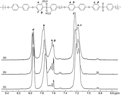
Initially, the polymerizability of the novel monomer osSDCDPS was successfully demonstrated. The reactivity under typical conditions for K2CO3-mediated nucleophilic aromatic substitution reactions was quite similar to the frequently employed isomeric monomer msSDCDPS, and the polymerisations involving osSDCDPS consequently produced copolymers with high intrinsic viscosities and good control of the compositions. Fig. 2 shows the 1H NMR spectra of the osSPAES series. As seen, the signals e, f and g corresponded to the protons of the sulfonated moieties and increased with the IEC. Concurrently, signals a, b, c and d originated from the protons of the non-sulfonated units and were found to decrease with the IEC. The IEC values of the three copolymers were calculated by using the integral of signal b and the combined integral of signals e and g, and were found to approximately match the target IEC. In addition, as seen in Table 1, the values are in a good agreement with the corresponding IEC values obtained by titration. All the osSPAES copolymers had high intrinsic viscosities.
 |
| | Fig. 2
1H NMR spectra of osSPAES copolymers with the IEC values (a) 1.88, (b) 1.44 and (c) 0.91 meq. g−1, recorded using DMSO-d6 solutions. | |
The three msSPAES copolymers were prepared with reasonably high intrinsic viscosities and a good control of the IEC value (Table 1). The oeSPAES copolymers were prepared under mild conditions using trimethylsilyl chlorosulfonate as the sulfonation reagent.26–28 No significant difference in intrinsic viscosity was found between the oeSPAES copolymers, indicating that no significant decomposition and crosslinking reaction had taken place during the sulfonation. Detailed descriptions of the msSPAES and oeSPAES synthesis, as well as the 1H NMR spectra of these polymers, are available as ESI†. All the polymers formed mechanically tough membranes after casting from DMSO solutions at 80 °C.
3.3. Membrane water uptake and proton conductivity
Water uptake is an important factor that facilitates proton conduction and determines much of the mechanical durability, especially during dry–wet cycles in a fuel cell. First, the water uptake of all the membranes was measured gravimetrically under immersed conditions at room temperature. The resulting water uptake and λ are shown in Fig. 3a and b, respectively. In general, the water uptake increased progressively with the IEC value. The highest water uptake was observed for the msSPAES copolymers, resulting in an excessive swelling at the highest IEC value. The excessive water uptake of this membrane may be partly due to its low molecular weight, as msSPAESh showed a low intrinsic viscosity (Table 1). In contrast, the other two series of copolymers showed less water uptake and lower λ values. Particularly the osSPAES copolymers were found to have the lowest water uptake at the highest IEC values.
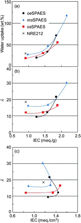 |
| | Fig. 3 Variation of membrane (a) water uptake and (b) λ values with the mass-based IEC, and variation of (c) λ values with the volume-based IEC. Data were obtained with the membranes under immersed conditions at room temperature. The corresponding data of NRE212 were added for comparison (the thin lines are a guide for the eyes only). | |
Volume-based parameters including water volume fraction and IECv were used in order to further analyze the water uptake behaviour of the membranes.29 In the calculation of these parameters, the densities of the membranes were estimated from previously published density data on msSPAES copolymers with different IEC values.30 Because of the structural similarity with the present copolymers, the estimated values should be quite accurate. The density as a function of IEC is shown as ESI†, and the estimated densities are collected in Table 2. Fig. 3c shows λ as a function of IECv (meq.cm−3). The data of both the oeSPAES and the msSPAES membranes expectedly developed ‘U’ shaped curves, which indicated that these materials reached the water percolation threshold of excessive swelling.30 Notably, the osSPAES copolymers did not display such an excessive swelling even at the highest IEC. This is advantageous for the dimensional stability and the mechanical durability of the membranes during fuel cell operation.
Table 2 Membrane properties
|
|
IECtitr./meq. g−1 |
IECv/meq. cm−3 |
ρ
p
/g cm−3 |
WUb (wt%) |
λ
|
σ @ 20 °C/mS cm−1 |
σ @ 80 °C/mS cm−1 |
σ @ 30%/mS cm−1 |
σ @ 90%/mS cm−1 |
|
Estimated values according to ref. 30.
Measured at room temperature under immersed conditions.
|
|
oeSPAESl |
1.24 |
1.25 |
1.28 |
21.0 |
9.4 |
14 |
35 |
— |
— |
|
oeSPAESm |
1.57 |
1.44 |
1.35 |
34.6 |
12.3 |
34 |
76 |
0.01 |
7.08 |
|
oeSPAESh |
1.84 |
1.28 |
1.40 |
72.0 |
21.7 |
61 |
129 |
0.08 |
22.26 |
|
msSPAESl |
0.98 |
0.89 |
1.23 |
29.0 |
16.4 |
13 |
33 |
— |
— |
|
msSPAESm |
1.59 |
1.30 |
1.35 |
48.3 |
16.9 |
60 |
118 |
0.19 |
25.30 |
|
msSPAESh |
2.16 |
1.15 |
1.46 |
118.3 |
30.4 |
60 |
97 |
1.92 |
83.47 |
|
osSPAESl |
0.91 |
0.84 |
1.22 |
19.8 |
12.1 |
2 |
4 |
— |
— |
|
osSPAESm |
1.44 |
1.34 |
1.32 |
31.6 |
12.2 |
19 |
44 |
0.09 |
8.18 |
|
osSPAESh |
1.88 |
1.48 |
1.41 |
56.2 |
16.6 |
56 |
115 |
0.50 |
31.88 |
| NRE212 |
0.91 |
1.17 |
1.97 |
30.3 |
18.5 |
72 |
152 |
10.05 |
101.63 |
As anticipated, the water uptake under immersed conditions increased with the temperature (Fig. 4a). Still, with the exception of membrane msSPAESh, all the membranes showed a water uptake below 100% at 100 °C. The excessive water uptake of msSPAESh led to very high λ values, 30 at 20 °C and approaching 100 at 100 °C. In comparison with NRE212, the λ value of oeSPAESh was higher in the investigated temperature range, while membranes msSPAESm and oeSPAESm showed lower values than NRE212 (Fig. 4b). The osSPAES copolymers displayed a quite restricted water uptake up to 100 °C, which was in agreement with the results shown in Fig. 3c.
 |
| | Fig. 4 Variation of membrane: (a) water uptake and (b) λ value with the temperature under immersed conditions. The corresponding data of NRE212 were added for comparison. | |
The in-plane proton conductivity of fully hydrated membranes was measured by a two-probe method between −20 and 100 °C (Fig. 5a). As expected, the proton conductivity increased with the temperature for all membranes. A sharp increase occurred between 0 and 20 °C because of the enhanced mobility of water caused by the melting of the ice. In addition, increasing IEC values led to increasing proton conductivities, except for msSPAESh. This membrane showed lower proton conductivities than msSPAESm, especially at high temperatures, because of the dilution of acidic groups caused by the excessive swelling. Notably, the osSPAES membranes showed higher proton conductivities at sub-zero temperatures, which is advantageous for fuel cell operation in cold climates. This can be explained by the acidic concentration in the hydrated membranes.31 As shown in Fig. 4b, the osSPAES membranes showed lower λ values than the msSPAES membranes. This meant that the osSPAES membranes had a higher fraction of strongly bound and highly polarized water than the other membranes. This in turn impeded the freezing of the water in the conducting channels at sub-zero temperatures. The osSPAES membranes showed slightly lower proton conductivities at temperatures above 0 °C than the oeSPAES membranes, and the osSPAESh and oeSPAESh membranes showed only slightly lower proton conductivity than NRE212.
 |
| | Fig. 5 Proton conductivity data of the sulfonated membranes (a) under immersed conditions as a function of temperature and (b) as a function of relative humidity at 80 °C. The corresponding data of NRE212 were added for comparison. | |
The humidity dependence of the proton conductivity is important from an application point of view. Thus, measurements were performed under controlled humidity between 30 and 90% RH in a closed system at 80 °C. As seen in Fig. 5b, the conductivity decreased with decreasing RH because of reduced water uptake and mobility. Membrane msSPAESh displayed the highest conductivity of the SPAES membranes under these conditions, most probably because of its high water uptake. The oeSPAESm and the osSPAESm copolymers showed similar proton conductivity at 90% RH, and these membranes had the same water uptake under fully immersed conditions. As the RH decreased, the msSPAES and the osSPAES membranes performed better than the oeSPAES membranes. This may support that the disulfonated monomer residues of the two former series of membranes improved the connectivity of the hydrophilic sequences, in relation to the latter series of membranes that are more likely to have isolated sulfonic acid units in the backbone as a result of the post-sulfonation. The conductivity of msSPAESm membrane was higher than that of osSPAESm because of the higher water uptake of the former at high humidifications (Fig. 4). Still, the proton conductivity of msSPAESm decreased more than that of osSPAESm when the RH was reduced.
Fig. 6a and b show the water volume fraction and IECv, respectively, versus temperature under immersed conditions. It is clearly seen that membrane msSPAESh showed a distinctly high water volume fraction and a low IECv value in the studied temperature range because of its excessive water uptake. In contrast, the other membranes kept a moderate increase in the water volume fraction, and a slight decrease in the IECv, with increasing temperature. As seen, the osSPAES membranes showed the lowest water volume fractions, or the highest IECv values, when compared with membranes of similar levels of IEC. The water volume fraction of the msSPAESm membrane was the same as for the osSPAESh membrane at 100 °C in water (Fig. 6a), which indicated a high dimensional stability of the latter membrane. Furthermore, the osSPAESh showed the highest IECv values in the studied temperature range (Fig. 6b), to indicate the highest local acid concentration in the hydrated membranes.
 |
| | Fig. 6 Temperature dependence of (a) the water volume fraction, (b) IECv and (c) the proton conductivity in the water channel of the sulfonated membranes. The corresponding data of NRE212 were added for comparison. | |
Fig. 6c shows the proton conductivity normalized to take into account the water volume fraction. This parameter thus indicates the efficiency of the absorbed water for the transport of protons. The proton conductivities in the water channel of all SPAES membranes under immersed conditions were found between 0.05 and 0.3 S cm−1 with steady increases as a function of temperature, despite different IEC values. All the values were significantly lower than those of NRE212, which demonstrated the excellent ability of this membrane to conduct protons. At 80 °C, the values of the msSPAESh membrane, which showed excessive swelling (Fig. 4), merged with those of the osSPAESm, which showed the lowest proton conductivity under immersed conditions (Fig. 5a). In conclusion, the osSPAES membranes utilized the water the most efficiently of all the three series of membranes.
The effective proton mobility in the membrane, μ, was derived from the proton conductivity data under immersed conditions. Generally, the effective proton mobility increases if an increase in the water content results in an increased proton dissociation, and if the water content in the membranes changes the size and shape of the water channels leading to a more effective proton/water transport pathway.31,32 Because the sulfonic acid dissociates already at quite low water contents due to its strong acidity, the change in the water-filled channels will be important for the effective proton mobility in the present case. Fig. 7a shows that the proton mobility increased as a function of temperature for all membranes because of the increasing water contents with temperature. Moreover, membranes with high IEC values within a given series showed high effective proton mobilities. Membrane msSPAESh displayed the highest mobility, superior to that of NRE212 in the full temperature range. However, as already mentioned, the msSPAESh reached a λ value of approximately 100 because of excessive swelling. It is desirable that membranes have a low water uptake and a high effective proton mobility, which produces data points in the upper left corner of Fig. 7b. In general, a linear correlation between λ and μ was found for all membranes except for msSPAESh. This indicated a similar structure of the proton conducting water channels in the SPAES membranes at a given λ. Observing the data in Fig. 7b of the membranes with the medium level of IEC (filled symbols), oeSPAESm and osSPAESm were found at low λ values with low μ values in comparison with NRE212. On the other hand, the data of msSPAESm were quite similar to NRE212. This implied that the IEC values of the former two membranes should be increased in order to reach the same effective proton mobility as NRE212, while the latter membrane already possessed a sufficient IEC value under immersed conditions. Consequently, the oeSPAESh and the osSPAESh membranes showed a comparable mobility to that of NRE212. In addition, osSPAESh showed a remarkably restricted water uptake.
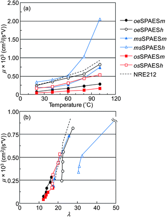 |
| | Fig. 7 Effective proton mobility of the sulfonated membranes as a function of (a) temperature in water and (b) the corresponding hydration number. NRE212 was added for comparison. | |
3.4. Membrane degradation
In general, the stability of sulfonic acid derivatives of aromatic polymers is significantly lower than for their non-sulfonated analogues. The high demands for membrane durability during fuel cell operation thus necessitate a careful characterization of the degradation reactions of sulfonated membranes. Chemical degradation may be caused by acid–base reactions and radical attacks induced by redox reactions.34 The occurrence of these reactions has a strong impact on the performance loss and lifetime of the membranes.
Initially, the thermal stability of the present membranes was investigated using TGA measurements in order to identify differences in the thermal stability based on the position of the sulfonic acid groups. Since small variations may influence the TGA results, all the measurements were carefully controlled, including the shape (film) and amount (2–3 mg) of the samples. The membranes were analyzed under N2 atmosphere at 10 °C min−1, as well as under more severe conditions under air at 1 °C min−1. The resulting TGA traces are seen in Fig. 8 and the resulting Td values are collected in Table 1. As expected, membranes in the Na+ form gave higher Td values than the corresponding membranes in the H+ form. Moreover, membranes with higher IEC values tended to degrade at lower temperatures. For the membranes in the H+ form, no conclusive result was obtained concerning the influence of the acid position on the stability of the three copolymer series. However, with the membranes in the Na+ form, the osSPAE membranes consistently showed 20–30 °C lower Td values in comparison with the other series. This indicated that the sodium sulfonate groups placed in ortho positions to the sulfone bridges decreased the stability.
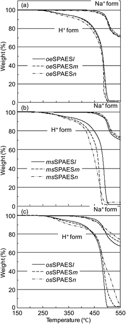 |
| | Fig. 8 TGA traces of (a) the oeSPAES, (b) the msSPAES and (c) the osSPAES series of membranes in the H+ form (1 °C min−1 under air) and in the Na+ form (10 °C min−1 under N2). | |
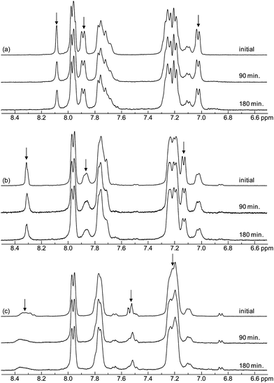
Tests based on Fenton's reagent, i.e. a solution of hydrogen peroxide and ferrous iron catalyst, are often used to simulate peroxide attack on membranes before carrying out long-term fuel cell tests.35 The durability of membranes immersed in Fenton's reagent thus provides a measure of the resistance towards oxidative degradation induced by primarily HO˙ and HOO˙ attack. The level of degradation is usually measured as a loss in membrane weight. In the case of SPAES copolymers, Fenton's test has shown to induce not only desulfonation but also chain-scissions as previously reported by Lawrence and Yamaguchi.35 For the present comparative study, a relatively mild condition was chosen with 3 ppm of Fe2+ at 60 °C. Fig. 9a shows the remaining weight of the membranes as a function of the time immersed in Fenton's reagent. As seen, the msSPAESh membrane degraded the fastest, most probably because the radical attack was facilitated by the excessive swelling. On the other hand, the msSPAESm membrane showed the slowest degradation, perhaps because of its high molecular weight as indicated by the intrinsic viscosity of the copolymer. For the membranes in the osSPAES and oeSPAES series, the samples with lower IEC values were found to lose weight faster than those with higher values. The degradation was also followed by analyzing the structural changes and the remaining IEC values of the immersed materials by 1H NMR spectroscopy. Fig. 10 shows the 1H NMR spectra of the copolymers with medium IEC values after different immersion times in Fenton's reagent. Clear and systematic changes in the signal intensities were observed as a function of immersion time. Specifically, the signals originating from the sulfonated arylene rings decreased over time in comparison to the signals of the non-sulfonated ones. Fig. 9b shows the remaining IEC values calculated from the NMR spectra shown in Fig. 10. As a result, the membranes with higher IECs showed a higher rate of IEC loss than those with lower IECs within each membrane series. This coincided with the level of water uptake. In addition, it was obvious that the osSPAES membrane resisted degradation better than the oeSPAES and the msSPAES membranes. For example, membrane osSPAESh lost less than 5 wt% of the IEC over 3 h, while membranes oeSPAESh and msSPAESh lost more than 10 wt% during the same time.
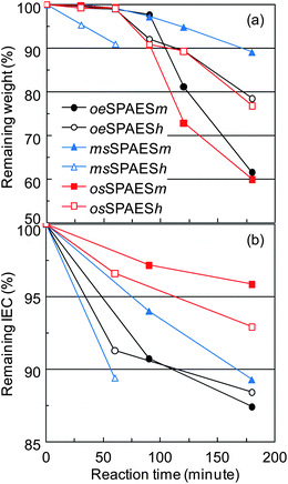 |
| | Fig. 9 Influence of Fenton's reagent on (a) remaining membrane weight and (b) remaining IEC as a function of immersion time for the different sulfonated membranes. | |
 |
| | Fig. 10
1H NMR spectra of (a) the oeSPAESm, (b) the msSPAESm, and (c) the osSPAESm copolymers before and after immersion in Fenton's reagent. The arrows indicate shifts originating from the sulfonated units, which tended to decrease in intensity with the immersion time. | |
Desulfonation by hydrolysis of sulfonic acid groups leads to decreased IEC, and thus degrading membrane performance over time. This reaction is likely to occur at the elevated temperatures and the high water activities typically found during fuel cell operation, and the rate is primarily determined by the stability of the intermediate σ-complex formed by the protonation of the carbon which carries the sulfonic group in the aromatic ring.20 In turn, the stability of the σ-complex is affected by the substitutions of the aromatic rings in the polymer. Electron-withdrawing sulfone or ketone bridges in the ortho and para positions to the sulfonic acid group destabilize the σ-complex, and can consequently be expected to increase the stability towards desulfonation. On the other hand, electron-donating ether bridges in ortho and para positions to the sulfonic acid group stabilize the σ-complex, resulting in hydrolytically less stable aromatic sulfonic acid groups.
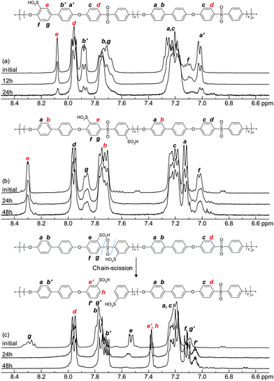
In order to evaluate the membrane degradation under accelerated hydrolytic conditions, the present membranes were immersed in 0.1 M aq. HCl and heated in a sealed pressure-sustainable autoclave. Initially, hydrolysis was attempted at 150 °C. However, no degradation was detected by 1H NMR spectroscopy after 24 hours, although all the membranes dissolved under the high temperature and pressure during the test. Next, membranes were kept at 200 °C in 0.1 M aq. HCl, and the result showed a degradation reaction for each series of membranes. In addition, the membranes were kept at 200 °C in neutral deionized water in order to study any difference from that under the acidic condition. As a result, a slower degradation reaction was found (see details as ESI†), which agreed well with the results found by Lehmann et al.36 The conditions in 0.1 M aq. HCl at 200 °C were found to be appropriate and convenient for the hydrolysis test. Under these conditions the membranes also dissolved, and an appreciable degradation of the sulfonated polymers was detected within a few hours. 1H NMR spectroscopy was used to analyze the remaining sulfonic acid groups, i.e., the IEC of the polymers, after removing the aq. HCl by evaporation. Fig. 11 shows the spectra of sulfonated polymers after different hydrolysis times. As seen, there were systematic changes as a function of the hydrolysis test time. The oeSPAES and the msSPAES copolymers degraded similarly as noted during the Fenton's test. In contrast, the spectra of the osSPAES copolymers showed some new shifts appearing and other shifts disappearing over time, indicating a different degradation mechanism. Kopitzke et al. have previously reported on the thermal stability of PAES and the corresponding SPAES derivatives under saturated vapour conditions, where water vapour at 100 °C was fed to a sample tube by argon gas.22 They identified decomposition products arising from polymer chain cleavage at both ether and sulfone bridges. On the other hand, thermogravimetric analyses of non-sulfonated PAES have previously shown that the sulfone bridge is the weakest link in the backbone. This bridge is more thermally unstable than, e.g., phenyl–phenyl or ether linkages,37–39 also in the presence of water.40 Our results suggested that the osSPAES copolymers degraded primarily through cleavage of the sulfone bridges (Fig. 11c). A further indication of this was a characteristic smell of sulfur when opening the autoclave with the osSPAES membranes after the hydrolysis test. Consequently, scission of the sulfone bridges was considered as the main degradation mechanism of the osSPAES copolymers in order to calculate the IEC value from the NMR data. The remaining percentage of the sulfonic acid groups was evaluated by comparing signals d and e of the oeSPAES copolymers, signals b and e for the msSPAES copolymers, and signals e′ and h for the osSPAES copolymers. Fig. 12 shows the remaining IEC percentage as a function of the hydrolysis time. As seen, all the copolymers displayed a loss of IEC over time. However, the samples with the high IEC values lost a lower percentage of the IEC value, an observation common for all the copolymer series. The most striking finding was however the severe loss of IEC displayed by the copolymers in the oeSPAES series, where more than 70% of the IEC was lost after 24 hours. In comparison, the copolymers of the msSPAES and the osSPAES series lost roughly 25% of the IEC after 48 hours. The IEC retention osSPAESh even seemed to level out above 80% after 24 h. These results strongly indicated the stabilizing effect of the electron-withdrawing sulfone bridge on the sulfonic acid units of the msSPAES and the osSPAES copolymers, leading to enhanced resistance against desulfonation. This is in agreement with theoretical considerations.20
 |
| | Fig. 11
1H NMR spectra of (a) the oeSPAESm, (b) the msSPAESm and (c) the osSPAESm copolymers before and after the accelerated hydrolysis test where the membranes were treated in 0.1 M aq. HCl at 200 °C in a sealed vessel. | |
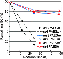 |
| | Fig. 12 Effect of the accelerated hydrolysis test on the IEC of the sulfonated polymers. Data were evaluated by 1H NMR spectroscopy after different treatment periods in 0.1 M aq. HCl at 200 °C in a sealed vessel. | |
Titration of the membrane residues was conducted after the accelerated hydrolysis test, not only to complement the IEC values calculated from 1H NMR data, but also to obtain support for the proposed degradation mechanism of the osSPAES copolymers where chain scission occurs by cleavage of the sulfone bridges of the disulfonated units, resulting in the loss of SO2. The residues of the oeSPAES membranes after 24 h hydrolysis and the residues of msSPAES and osSPAES membranes after 48 h hydrolysis were used. As seen in Table 3, the data by 1H NMR spectroscopy and acid–base titration agreed reasonably well.
Table 3 IEC values and viscosities of the copolymers after the accelerated hydrolysis in 0.1 M HCl at 200 °C in a sealed vessel
|
|
Hydrolysis test/hours |
IECNMR/meq. g−1 |
Remaining IECa (%) |
IECtitr./meq. g−1 |
[η]/dL g−1 |
Reduction in [η]a (%) |
|
Calculated from the difference before and after the hydrolysis test.
|
|
oeSPAESm |
24 |
0.20 |
13% |
<0.10 |
0.29 |
48 |
|
oeSPAESh |
24 |
0.50 |
27% |
0.58 |
0.30 |
46 |
|
msSPAESm |
48 |
1.19 |
75% |
1.16 |
0.50 |
17 |
|
msSPAESh |
48 |
1.66 |
77% |
1.54 |
0.36 |
8 |
|
osSPAESm |
48 |
1.08 |
73% |
1.10 |
0.10 |
74 |
|
osSPAESh |
48 |
1.54 |
74% |
1.49 |
0.09 |
82 |
All the membrane copolymers showed a decreased intrinsic viscosity after the hydrolysis test (Table 3). Both desulfonation and chain scission are likely to lead to decreased viscosity values. However, chain scissions and the subsequent reduction of molecular weight were expected to have the highest impact. The viscosity reduction was most pronounced for the osSPAES series and the lowest for the msSPAES series. For the oeSPAES series, the viscosities after the accelerated hydrolysis test were still higher than that of the native Radel® PPSU, which had a viscosity of 0.23 dL g−1 under the same measurement conditions. Notably, the hydrolysed samples from the oeSPAES and the msSPAES series formed tough membranes after recasting from DMSO. However, it was not possible to form films of the hydrolysed samples from the osSPAES series. This further indicated that the osSPAES polymers degraded via chain scission.
4. Conclusions
Three series of SPAESs with different positions of the sulfonic acid groups, but with an identical fully aromatic backbone structure, were prepared and studied in order to investigate variations in properties and stability as membrane materials. In the course of this work, 2,2′-disulfonated DCDPS was successfully synthesized via lithiation, sulfination and oxidation of DCDPS. The new monomer was copolymerized to produce osSPAES with the sulfonic acid units in the ortho positions to the sulfone bridges. The subsequent comparative study of solvent cast membranes showed some advantages of the osSPAES series. In comparison to the oeSPAES and msSPAES series, with sulfonic acid groups in the ortho position to the ether bridges and in meta positions to the sulfone bridges, respectively, the osSPAES series showed a more restricted water uptake and a slightly lower proton conductivity under immersed conditions between 20 and 100 °C at a given IEC value. However, at sub-zero temperatures the osSPAES series showed a higher conductivity. Moreover, the proton conductivity of the msSPAES and osSPAES series suffered less than that oeSPAES series when the RH was decreased. It may be that the higher local concentration of sulfonic acid in the former two series, because of their disulfonated sites, provided a more efficient pathway for proton conduction. Thermogravimetric results did not show any differences in stability based on the placement of the sulfonic acid units. The 1H NMR analysis of membranes subjected to Fenton's test suggested that the osSPAES had the best oxidative stability. All the membranes were found to dissolve during the accelerated hydrolysis test at 200 °C. Although the analysis of the dissolved polymers by 1H NMR spectroscopy showed a reduction of the IEC of the membranes in all three series, the loss was especially dramatic for the oeSPAES membranes. Spectra of the osSPAES series suggested that the polymers degraded by scission of the sulfone bridges. The close positioning of the sulfonic acid groups to the sulfone bridges may destabilize the latter. The occurrence of chain scission during the test was supported by sharp reductions in the intrinsic viscosity of the osSPAES. It should be pointed out that the conditions of the test were very severe, and were chosen to provide appreciable membrane and polymer degradation within only a few hours. Future hydrolysis tests under milder conditions will show if these reactions are significant also under more realistic conditions during fuel cell operation. The results obtained with the different SPAES of this work can be useful in future rational designs of stable sulfonated polymers for proton-exchange membranes.
Acknowledgements
We thank the Danish Council for Strategic Research for financial support through contract no. 09-065198.
References
- G. M. Geise, H.-S. Lee, D. J. Miller, B. D. Freeman, J. E. McGrath and D. R. Paul, J. Polym. Sci., Part B: Polym. Phys., 2010, 48, 1685 CrossRef CAS.
- D. Y. Chen, S. J. Wang, M. Xiao and Y. Z. Meng, Energy Environ. Sci., 2010, 3, 622 CAS.
- S. Bose, T. Kuila, X. L. N. Thi, N. H. Kim, K. T. Lau and J. H. Lee, Prog. Polym. Sci., 2011, 36, 813 CrossRef CAS.
- Y. Wang, K. S. Chen, J. Mishler, S. C. Cho and X. C. Adroher, Appl. Energy, 2011, 88, 981 CrossRef CAS.
-
The Fuel Cell Today Industry Review, Fulmar Colour Printing Co. Ltd., 2011, ISSN:1756–3186 Search PubMed.
- A. Pozio, A. Cemmi, F. Mura, A. Masci, E. Serra and R. F. Silva, J. Solid State Electrochem., 2011, 15, 1209 CrossRef CAS.
- S. Xiao, H. Zhang, X. Li and Z. Mai, Int. J. Hydrogen Energy, 2011, 36, 10934 CrossRef CAS.
- A. Kusoglu, M. H. Santare and A. M. Karlsson, J. Polym. Sci., Part B: Polym. Phys., 2011, 49, 1506 CrossRef CAS.
- C. H. Park, C. H. Lee, M. D. Guiver and Y. M. Lee, Prog. Polym. Sci., 2011, 36, 1443 CrossRef CAS.
- Y. Yang, A. Siu, T. J. Peckham and S. Holdcroft, Adv. Polym. Sci., 2008, 215, 55 CAS.
- G. Maier and J. Meier-Haack, Adv. Polym. Sci., 2008, 216, 1 CAS.
- J. Roziere and D. J. Jones, Annu. Rev. Mater. Res., 2003, 33, 503 CrossRef CAS.
- T. Okanishi, Y. Tsuji, Y. Sakiyama, S. Matsuno, B. Bae, K. Miyatake, M. Uchida and M. Watanabe, Electrochim. Acta, 2011, 56, 8989 CrossRef CAS.
- C. Iojoiu, M. Marechal, F. Chabert and J. Y. Sanchez, Fuel Cells, 2005, 5, 344 CrossRef CAS.
- W. L. Harrison, M. A. Hickner, Y. S. Kim and J. E. McGrath, Fuel Cells, 2005, 5, 201 CrossRef CAS.
- M. A. Hickner, H. Ghassemi, Y. S. Kim, B. R. Einsla and J. E. McGrath, Chem. Rev., 2004, 104, 4587 CrossRef CAS.
- S. Takamuku and P. Jannasch, Adv. Energy Mater., 2012, 2, 129 CrossRef CAS.
- S. Takamuku and P. Jannasch, Macromol. Rapid Commun., 2011, 32, 474 CrossRef CAS.
- E. P. Jutemar, S. Takamuku and P. Jannasch, Polym. Chem., 2011, 2, 181 RSC.
- M. Schuster, K.-D. Kreuer, H. T. Andersen and J. Maier, Macromolecules, 2007, 40, 598 CrossRef CAS.
- M. Schuster, C. C. Araujo, V. Atanasov, H. T. Andersen, K.-D. Kreuer and J. Maier, Macromolecules, 2009, 42, 3129 CrossRef CAS.
- R. W. Kopitzke, C. A. Linkous and G. L. Nelson, Polym. Degrad. Stab., 2000, 67, 335 CrossRef CAS.
- S. Chen, Y. Yin, H. Kita and K. Okamoto, J. Polym. Sci., Part A: Polym. Chem., 2007, 45, 2797 CrossRef CAS.
- H. Hou, M. L. D. Vona and P. Knauth, ChemSusChem, 2011, 4, 1526 CrossRef CAS.
- D. Xing and J. Kerres, Polym. Adv. Technol., 2006, 17, 591 CrossRef CAS.
- J. Yu, C. Dong, J. Liu, C. Li, J. Fang and R. Guan, J. Mater. Sci., 2010, 45, 1017 CrossRef CAS.
- L. M. Carvalho, A. R. Tan and A. S. Gomes, J. Appl. Polym. Sci., 2008, 110, 1690 CrossRef.
- K. Matsumoto, T. Nakagawa, T. Higashihara and M. Ueda, J. Polym. Sci., Part A: Polym. Chem., 2009, 47, 5827 CrossRef CAS.
- Y. S. Kim and B. S. Pivovar, Annu. Rev. Chem. Biomol. Eng., 2010, 1, 123 CrossRef CAS.
- Y. S. Kim, B. Einsla, M. Sankir, W. Harrison and B. S. Pivovar, Polymer, 2006, 47, 4026 CrossRef CAS.
- A. Siu, J. Schmeisser and S. Holdcroft, J. Phys. Chem. B, 2006, 110, 6072 CrossRef CAS.
- T. J. Peckham, J. Schmeisser, M. Rodgers and S. Holdcroft, J. Mater. Chem., 2007, 17, 3255 RSC.
- P. Jannasch, Fuel Cells, 2005, 5, 248 CrossRef CAS.
- R. Borup, J. Meyers, B. Pivovar, Y. S. Kim, R. Mukundan, N. Garland, D. Myers, M. Wilson, F. Garzon, D. Wood, P. Zelenay, K. More, K. Stroh, T. Zawodzinski, J. Boncella, J. E. McGrath, M. Inaba, K. Miyatake, M. Hori, K. Ota, Z. Ogumi, S. Miyata, A. Nishikata, Z. Siroma, Y. Uchimoto, K. Yasuda, K. Kimijima and N. Iwashita, Chem. Rev., 2007, 107, 3904 CrossRef CAS.
- J. Lawrence and T. Yamaguchi, J. Membr. Sci., 2008, 325, 633 CrossRef CAS.
- C. Vogel, J. Meier-Haack, A. Taeger and D. Lehmann, Fuel Cells, 2004, 4, 320 CrossRef CAS.
- G. F. L. Ehlers, K. R. Fisch and W. R. Powell, J. Polym. Sci., Part A-1, 1969, 7, 2955 CrossRef CAS.
- S. T. Ellison, A. P. Gies, D. M. Hercules and S. L. Morgan, Macromolecules, 2009, 42, 5526 CrossRef CAS.
- L.-H. Perng, J. Appl. Polym. Sci., 2001, 81, 2387 CrossRef CAS.
- I. I. Levantovskaya, G. V. Dralyuk, O. A. Mochalova, I. A. Yurkova, M. S. Akutin and B. M. Kovarskaya, Vysokomolekulyarnye Soedineniya, 1971, 13, 8 CAS.
Footnote |
| † Electronic supplementary information (ESI) available. See DOI: 10.1039/c2py00611a |
|
| This journal is © The Royal Society of Chemistry 2012 |
Click here to see how this site uses Cookies. View our privacy policy here. 


![[thin space (1/6-em)]](https://www.rsc.org/images/entities/char_2009.gif) :
:![[thin space (1/6-em)]](https://www.rsc.org/images/entities/char_2009.gif) 1.00. After the sulfination and salt out of the product, small amounts of insoluble byproducts were readily removed by filtration and recrystallization in water/2-propanol. Fig. 1 shows the 1H NMR spectra of osSDCDPS and msSDCDPS. As seen, no resonance signals above 8 ppm were observed in the spectrum of osSDCDPS. Signal a, arising from the protons in-between the sulfonic acid group and the chlorine atom, appeared at 7.6–7.7 ppm and overlapped with signal b. The spectrum of msSDCDPS showed a signal a at 8.3–8.4 ppm, corresponding to the protons between the sulfone bridge and the sulfonic acid group. The integrals of the signals were in excellent agreement with the two target structures and no unknown signals were observed.
1.00. After the sulfination and salt out of the product, small amounts of insoluble byproducts were readily removed by filtration and recrystallization in water/2-propanol. Fig. 1 shows the 1H NMR spectra of osSDCDPS and msSDCDPS. As seen, no resonance signals above 8 ppm were observed in the spectrum of osSDCDPS. Signal a, arising from the protons in-between the sulfonic acid group and the chlorine atom, appeared at 7.6–7.7 ppm and overlapped with signal b. The spectrum of msSDCDPS showed a signal a at 8.3–8.4 ppm, corresponding to the protons between the sulfone bridge and the sulfonic acid group. The integrals of the signals were in excellent agreement with the two target structures and no unknown signals were observed.


