Deep tissue bio-imaging using two-photon excited CdTe fluorescent quantum dots working within the biological window
L. M.
Maestro
a,
J. E.
Ramírez-Hernández
b,
N.
Bogdan
c,
J. A.
Capobianco
c,
F.
Vetrone
d,
J. García
Solé
a and
D.
Jaque
*a
aFluorescence Imaging Group, Departamento de Física de Materiales, Facultad de Ciencias, Universidad Autónoma de Madrid, Madrid, 28049, Spain. E-mail: lm.maestro@uam.es; daniel.jaque@uam.es; jose.garcia_sole@uam.es; Fax: +34 91 497 8579; Tel: +34 914975283
bDepartamento de Investigación en Física, Universidad de Sonora, Hermosillo, 5-8883190, México. E-mail: nitormz@gmail.com; Fax: +52 6622592253; Tel: +52 6622592156
cDepartment of Chemistry and Biochemistry, Concordia University, Montreal, QC H4B 1R6, Canada. E-mail: nbogdan@alcor.concordia.ca; capo@vax2.concordia.ca; Fax: +1 514-848-2868; Tel: +1 514-848-2424 ext. 3350
dInstitut National de la Recherche Scientifique—Énergie, Matériaux et Télécommunications, Université du Québec, Varennes, QC J3X 1S2, Canada. E-mail: vetrone@emt.inrs.ca; Fax: +1 450-929-8102; Tel: +1 514-228-6847
First published on 9th November 2011
Abstract
A new approach to deep tissue imaging is presented based on 8 nm CdTe semiconductor quantum dots (QDs). The characteristic 800 nm emission was found to be efficiently excited via two-photon absorption of 900 nm photons. The fact that both excitation and emission wavelengths lie within the “biological window” allows for high resolution fluorescence imaging at depths close to 2 mm. These penetration depths have been used to obtain the first deep tissue multiphoton excited fluorescence image based on CdTe-QDs. Due to the large thermal sensitivity of CdTe-QDs, one may envisage, in the near future, their use in high resolution deep-tissue thermal imaging.
1 Introduction
Semiconductor quantum dots (hereafter QDs) are perhaps one of the most widely used fluorescent probes in biomedical imaging applications.1,2 This is because they offer unique advantages over organic fluorophores such as chemical stability, high fluorescence quantum efficiency, and above all, the absence of relevant photo-bleaching.1–4 Many groups have invested in studying the surface chemistry of QDs to achieve full control over their surface properties. The surface chemistry has evolved such that the inherent toxicity of the QDs has been minimized (via the growth of a biocompatible shell) and the selective incorporation of QDs in cells and tissues has been facilitated (via the attachment of relevant targeting moiety).4,5 Furthermore, QDs show a large two-photon absorption cross-section.6 This, in combination with the advent of confocal and multiphoton excited fluorescence microscopes, has allowed high spatial resolution studies of cell dynamics and tissue morphologies.7–11 The interest in QDs has been recently propelled as a result of the high temperature sensitivity of their fluorescence bands.12,13 With the idea of exploiting this high thermal sensitivity, QDs have emerged as multi-functional optical probes capable of simultaneous optical imaging and thermal sensing. For example, very recently thermal sensitivities as low as 0.2 °C have been achieved using CdTe-QDs.13 This opens the door to many possibilities allowing, for example, the dynamical monitoring of intra-cellular reactions, which modify cellular temperature.It is well known that the emission wavelength of QDs is fully determined by their size where the emission shifts towards lower energy as the size increases. In most bio-imaging applications, visible emitting QDs are used.14–17 In the particular case of CdTe-QDs, this corresponds to a dot size of approximately 4 nm in order to get emission centered at approximately 650 nm. In principle, when using visible-emitting QDs for bio-imaging applications, two important factors must be considered. First, the quantum efficiency of QDs has been found to peak at intermediate QD sizes so that QDs emitting in the visible region show the largest fluorescence efficiency. Second, the detection efficiency of commercial multiphoton microscopes is optimized in the visible region. Despite this, the use of visible-emitting QDs limits their applications in real in vivo imaging since it restricts the optical penetration depths. This is because of the presence of visible absorbing components in tissues (such as melanin, hemoglobin and water).18 This fact, in combination with optical dispersion effects caused by inherent density fluctuations, leads to tissue extinction coefficients in excess of 20 cm−1, i.e. to optical penetration lengths below 500 μm.19 In order to increase the depth of penetration, QDs emitting in the near-infrared range (NIR, wavelengths larger than 700 nm) should be used. Taking this a step further, QDs should be excited via a multiphoton absorption process, such that the excitation wavelength (in the NIR) is longer than the emission wavelength in order to ensure high spatial resolution of the imaging process.20 It is worth mentioning that the excitation wavelength should not exceed 900 nm, so as to avoid water absorption (that also limits penetration depth of the excitation radiation). The use of excitation radiation with wavelengths in the 700–900 nm range not only provides large penetration depths and high spatial resolution, but also minimizes the risk of Cd photo-dissociation.21–23 This, in turn, would minimize the toxicity of CdTe-QDs that indeed is one of the main drawbacks limiting the use of QDs in bio-photonics.24 Thus, to perform deep tissue high resolution fluorescence imaging multiphoton excited QDs are required whose emission and excitation wavelengths both lie within the so-called “biological window” (700–900 nm).25 If these are met, and taking into account the typical weak absorption coefficients of tissues in the 700–900 nm range (∼6 cm−1), the optical penetration depth would be increased above 1 mm. Thus, any particular QD would be useful in terms of high resolution deep tissue imaging if the following two conditions are simultaneously satisfied: (i) the excitation and emission wavelengths should be between 700 and 900 nm, and (ii) secondly, the fluorescence should be produced by multiphoton excitation (excitation wavelength should be longer than the emission one). It is possible to find in the literature numerous examples dealing with QD for bio-imaging experiments; however, in those works only one of these two requirements is satisfied, not both simultaneously. As an example, deep tissue imaging was recently reported by using hybrid QDs simultaneously excited and emitting within the “biological window” but by one photon-excitation (excitation wavelength shorter than the emission one).26 This would lead to large penetration depths but limits the potential spatial resolution of the obtained images. On the other hand, there are numerous examples reporting on visible-emitting multiphoton excited QDs for bioimaging. In this case the obtained images are of superior spatial resolution but the strong extinction of the emission radiation makes deep tissue imaging difficult.27–32 Finally, there are also previously published works on bio-images obtained using NIR emitting QDs excited by visible radiation. In this case the use of an excitation wavelength lying out of the biological window limits the penetration depths down to about 0.8 mm.29 Thus, QDs simultaneously satisfying both the above-mentioned requirements (i.e. multiphoton excitation/emission within the 700–900 nm range) have not yet been reported. It should be noted that these requirements have been already satisfied by lanthanide-doped upconversion nanoparticles (UCNPs).33 However, the use of QDs instead of UCNPs would provide the additional possibility of deep tissue high-resolution thermal imaging based on the superior thermal sensitivity of QD fluorescence.13
2 Experimental
The NIR emitting CdTe-QDs investigated in this work were provided by Plasmachem Inc. and were obtained through an aqueous synthesis without phase transfer. The averaged QD diameter (determined by TEM) was approximately 8 nm. The CdTe-QDs were dispersed in distilled water with a concentration of 0.3 wt% and the solution was stable (no precipitation was observed after several months). The toxicity of our Cd containing QDs in HeLa cancer cells was evaluated following the MTT assay procedure. It was found that, after incubation of QDs (1012 per cm−3 of PBS) in HeLa cells for 18 hours, the cell viability (with respect to control HeLa cells) was reduced by less than 10%. Such minimal toxicity found in our experiments is in agreement with previous results that report on the absence of any appreciable toxicity of other Cd containing QDs.21–23 Multiphoton excitation of the CdTe-QDs was performed by using a mode-locked Ti:Sapphire laser tuned to 900 nm which provides 100 fs pulses with a repetition rate of 80 MHz. The phantom tissue used throughout this work was fabricated from a scattering medium (such as agar) containing several absorbing components (India ink and olive oil) so that the optical properties of human skin were mimicked.34–37 Two-photon excited fluorescence imaging experiments were performed using a custom-built confocal microscope. The 900 nm excitation radiation was focused into the CdTe-QDs solution by using a 50× long working distance microscope objective (0.65 NA). The two-photon excited luminescence (at around 800 nm) was collected by the same objective and, after passing several filters and apertures, was focused into a fiber-coupled high-resolution spectrometer. The images were obtained by scanning the focusing/collecting microscope objective. Note that in this configuration, excitation of the QDs does not require the use of visible photons, but rather the simultaneous absorption of two NIR photons, so that the strong tissue absorption in the visible region is avoided.3 Results and discussion
Fig. 1 shows the two-photon excited emission spectrum obtained for the solution containing 8 nm diameter CdTe-QDs following optical excitation using a Ti:Sapphire mode-locked laser tuned to 900 nm (the spectral line-shape of excitation radiation has been also included in Fig. 1). The emission intensity was found to be stable without any evidence of photo-bleaching. Two-photon excited emission was not found to be critically dependent on the excitation wavelength (as previously reported for similar QDs). In fact, efficient two-photon excitation was possible with a wide range of excitation wavelengths, from 830 to 940 nm, although the optimum pump wavelength was determined to be 900 nm. The data shown in Fig. 1 clearly reveal that 8 nm CdTe-QDs satisfy the first requirement for deep tissue bio-imaging: both the emission and absorption wavelengths lie within the biological window. The second important requirement is that the fluorescence must be excited through a multiphoton absorption process. To verify this, we have measured the dependence of the 800 nm emitted intensity as a function of the 900 nm excitation power (shown in Fig. 2(a)). The 800 nm emission intensity grows monotonously with the 900 nm excitation power without any evidence of saturation (as it occurs for lanthanide-doped upconverting nanoparticles). The slope in the double-logarithmic representation has been found to be 1.5. This reveals the presence of a two-photon excitation process. It is remarkable that, although the photon excitation order is well above 1, it is lower than that observed for two-photon excited-visible-emitting QDs (ranging from 1.7 to 2).3 We attribute this to the small quantum defect between the pumping and the emitted photons giving rise to the possible existence of other competitive excitation mechanisms involving only one excitation photon (such as phonon-assisted processes).38–41 The possible presence of phonon assisted absorption transitions in semiconductor QDs has been extensively studied in the past. Indeed, it was concluded that those phonon assisted processes are more probable for larger QDs (such as the ones used in this work), since for larger dot sizes the energy spacing between the quantum confined levels becomes comparable to the optical phonon energies.41 This would explain the lower slope obtained in this paper compared to those previously reported for smaller QDs.42 The presence of phonon assisted absorption processes would also imply that excitation of the 780 nm fluorescence band with lower energy photons could be also solely achieved by one-photon excitation, i.e. without the presence of multiphoton absorption processes. In order to verify this fact we tuned our Ti:Sapphire laser from the mode-locking regime to the continuous wave (CW) regime. By doing this we reduce the peak excitation intensity while keeping the same average excitation intensity. In smaller visible emitting QDs, this causes the quenching of the NIR-to-visible luminescence, because the peak photon intensity decreases by several orders of magnitude.42 Nevertheless, this emission quenching is not expected in larger QDs if phonon-assisted absorptions are taking place. This is, indeed, what we have experimentally observed in our case. When our 900 nm excitation laser was switched to CW we were still able to detect some weak emission at 800 nm (up-converted band) although much weaker than that observed when exciting with fs laser pulses.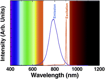 | ||
| Fig. 1 Emission spectrum generated by 8 nm CdTe-QDs when optically excited by a mode-locked Ti:Sapphire laser providing 100 fs pulses at 900 nm. The spectrum of the excitation laser line (tuned at this wavelength) is also included. The limits of the “biological window” are schematically indicated. | ||
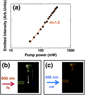 | ||
| Fig. 2 (a) Intensity of the 800 nm fluorescence band generated by CdTe-QDs as a function of the 900 nm excitation power. Dots are experimental data and the solid line is the best linear fit in a log–log scale. (b). Optical picture of the CdTe-QDs solution when a 900 nm 100 fs laser beam is tightly focused inside. Arrow indicates where the 800 nm luminescence is produced (at the focus of 900 nm beam). (c) Optical picture of the CdTe-QDs solution when a 488 nm CW laser beam is tightly focused inside. | ||
In order to obtain further confirmation about the presence of a two-photon excitation process, we have investigated the spatial location of the 800 nm emitting volume. Fig. 2(b) shows a photograph of the CdTe-QDs solution excited at 900 nm (using a 100 fs pulses) with the laser beam tightly focused inside the solution. It is evident that the 800 nm fluorescence is spatially located at the focus of the 900 nm excitation beam, i.e. in the volume where the maximum photon densities are achieved (and hence the multiphoton excitation probability becomes relevant). This is at variance with the spatial location of the fluorescence when it is generated via one-photon excitation (with a 488 nm CW argon laser, see Fig. 2(c)). In the latter case, it is clear that 800 nm emission is not localized at focus but all along the optical path of the excitation radiation.
Fig. 1 and 2 clearly demonstrate that “large” CdTe-QDs simultaneously overcome the spectral limitations that plague deep-tissue imaging. However, for real-world applications, the exact knowledge about the maximum optical tissue penetration depths that can be achieved using these QDs is required. For this purpose, we have fabricated a phantom tissue that mimics the optical properties of biological tissues (see details in Section 2). The ratio between the different components was adjusted in order to reproduce, at wavelengths below 700 nm, the absorption spectrum of human skin.34–37 The inset in Fig. 3 shows the extinction coefficient of human forearm skin in the visible region of the spectrum as reported by Kobayashi et al.28 As can be observed, human skin shows a background absorption/extinction coefficient close to 6 cm−1 for wavelengths above 700 nm. This non-vanishing extinction coefficient background is attributed to the presence of scattering due to the inhomogeneous nature of human skin. At shorter wavelengths, the presence of hemoglobin absorption leads to extinction coefficients as large as 10 cm−1. Finally, human skin also shows relevant extinction coefficients for wavelengths above 900 nm due to the presence of water absorption bands. All these features have been well reproduced by our phantom tissue, as can be observed from the extinction spectrum shown in Fig. 3(a). Moreover, the phantom tissue shows an extinction coefficient close to 10 cm−1 in the visible region and a 6 cm−1 extinction plateau extending from 700 up to 900 nm (limited in the NIR by the water absorption bands).
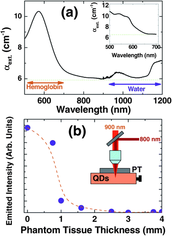 | ||
| Fig. 3 (a) Extinction coefficient of the phantom tissue used throughout this work. The inset shows the extinction coefficient corresponding to forearm human skin as reported by M. Kobayashi et al.28 Note that the phantom tissue well reproduces the background extinction coefficient as well as the visible absorption caused by hemoglobin. (b) Intensity of the multiphoton excited 800 nm fluorescence generated by a CdTe-QD solution as obtained through phantom tissue slices of different thickness. The inset shows a schematic diagram of the set-up used. | ||
To determine the tissue penetration depths achievable with our CdTe-QDs we have analyzed how the two-photon excited emitted intensity varied when phantom tissue slices of different thickness were placed between the focusing/collecting microscope objective and the CdTe-QDs solution (see the schematic drawing in the inset of Fig. 3(b)). The results shown in Fig. 3(b) show that, although the collected emission intensity drastically decreases with the phantom tissue thickness, appreciable fluorescence signals could still be obtained up to tissue thicknesses of 1.6 mm. These large penetration depths would allow for high resolution in vivofluorescence imaging of veins, tumor vasculature, carcinomas, as well as the cortex and hippocampus areas of the brain.29,43 Thus, we have provided here a direct measurement of the penetration depths achievable by using multiphoton excited QDs working within the biological window.
To explore the potential use of NIR emitting CdTe-QDs for deep tissue multiphoton excited fluorescence imaging, the CdTe-QD solution was placed below a 1.5 mm thick slice of phantom tissue (see Fig. 4 at the top). Between the CdTe-QD solution and the phantom tissue, a transparent film was placed on which the acronym UAM (Universidad Autonoma de Madrid) was negatively impressed (letters were transparent over an opaque background). The 900 nm excitation radiation was focused into the CdTe-QD solution through the phantom tissue and the printed film. The outgoing 800 nm fluorescence was collected through the same objective and its intensity was registered by a fiber-coupled spectrometer. By scanning the focusing/collecting microscope objective we were able to obtain the fluorescence image of the film located under the 1.5 mm thick tissue, as can be observed at the bottom of Fig. 4. To the best of our knowledge, this constitutes the first deep tissue fluorescence image obtained by two-photon excitation using NIR emitting CdTe-QDs. The results reported in this work constitute a new approach to obtain deep thermal high-resolution fluorescence images of in vivo systems.
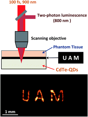 | ||
| Fig. 4 Schematic diagram of the set-up used to obtain deep tissue images by using the two-photon emission of NIR emitting CdTe-QDs. At the bottom we include the deep tissue image of a patterned transparent film in which the initials of Universidad Autonoma de Madrid were negatively printed. | ||
4 Conclusions
In summary, we have demonstrated that “large” (8 nm in diameter) CdTe quantum dots are ideal optical probes for deep tissue biological imaging. Their broadband luminescence centered at 800 nm can be efficiently excited by 900 nm laser pulses through a multiphoton excitation. We have experimentally demonstrated that, because both excitation and emission wavelengths lie within the “biological window”, optical penetration depths into tissues close to 2 mm can be achieved. These penetration depths have been used to obtain the first “deep tissue” image based on infrared excited/emitting quantum dots.Acknowledgements
This work was supported by the Universidad Autónoma de Madrid and Comunidad Autonoma de Madrid (Projects CCG087-UAM/MAT-4434 and S2009/MAT-1756), by the Spanish Ministerio de Educacion y Ciencia (MAT 2010-16116), by a Banco Santander CEAL-UAM project. J.A.C. thanks the Natural Sciences and Engineering Research Council (NSERC) of Canada and the Concordia University Research Chairs program for funding.Notes and references
- X. Michalet, F. F. Pinaud, L. A. Bentolila, J. M. Tsay, S. Doose, J. J. Li, G. Sundaresan, A. M. Wu, S. S. Gambhir and S. Weiss, Science, 2005, 307(5709), 538–544 CrossRef CAS.
- W. C. W. Chan and S. M. Nie, Science, 1998, 281(5385), 2016–2018 CrossRef CAS.
- D. R. Larson, W. R. Zipfel, R. M. Williams, S. W. Clark, M. P. Bruchez, F. W. Wise and W. W. Webb, Science, 2003, 300(5624), 1434–1436 CrossRef CAS.
- A. M. Derfus, W. C. W. Chan and S. N. Bhatia, Nano Lett., 2004, 4(1), 11–18 CrossRef CAS.
- I. L. Medintz, H. T. Uyeda, E. R. Goldman and H. Mattoussi, Nat. Mater., 2005, 4(6), 435–446 CrossRef CAS.
- G. S. He, K. T. Yong, Q. D. Zheng, Y. Sahoo, A. Baev, A. I. Ryasnyanskiy and P. N. Prasad, Opt. Express, 2007, 15(20), 12818–12833 CrossRef CAS.
- C. Xu, W. Zipfel, J. B. Shear, R. M. Williams and W. W. Webb, Proc. Natl. Acad. Sci. U. S. A., 1996, 93(20), 10763–10768 CrossRef CAS.
- J. Lovric, H. S. Bazzi, Y. Cuie, G. R. A. Fortin, F. M. Winnik and D. Maysinger, J. Mol. Med., 2005, 83(5), 377–385 CrossRef.
- Z. H. Li, K. M. Wang, W. H. Tan, J. Li, Z. Y. Fu, C. B. Ma, H. M. Li, X. X. He and J. B. Liu, Anal. Biochem., 2006, 354(2), 169–174 CrossRef CAS.
- P. Suriamoorthy, X. Zhang, G. Hao, A. Joly, S. Singh, M. Hossu, X. Sun and W. Chen, Cancer Nanotechnol., 2010, 1(1), 19–28 CrossRef CAS.
- W. Dong, L. Guo, M. Wang and S. Xu, J. Lumin., 2009, 129(9), 926–930 CrossRef CAS.
- L. M. Maestro, E. M. Rodriguez, F. S. Rodriguez, M. C. I. de la Cruz, A. Juarranz, R. Naccache, F. Vetrone, D. Jaque, J. A. Capobianco and J. G. Sole, Nano Lett., 2010, 10(12), 5109–5115 CrossRef CAS.
- L. M. Maestro, C. Jacinto, U. R. Silva, F. Vetrone, J. A. Capobianco, D. Jaque and J. G. Sole, Small, 2011, 7(13), 1774–1778 CrossRef CAS.
- X. L. Gao, J. Chen, J. Y. Chen, B. X. Wu, H. Z. Chen and X. G. Jiang, Bioconjugate Chem., 2008, 19(11), 2189–2195 CrossRef CAS.
- X. H. Gao, Y. Y. Cui, R. M. Levenson, L. W. K. Chung and S. M. Nie, Nat. Biotechnol., 2004, 22(8), 969–976 CrossRef CAS.
- M. Dahan, T. Laurence, F. Pinaud, D. S. Chemla, A. P. Alivisatos, M. Sauer and S. Weiss, Opt. Lett., 2001, 26(11), 825–827 CrossRef CAS.
- J. K. Jaiswal, H. Mattoussi, J. M. Mauro and S. M. Simon, Nat. Biotechnol., 2003, 21(1), 47–51 CrossRef CAS.
- J. V. Frangioni, Curr. Opin. Chem. Biol., 2003, 7(5), 626–634 CrossRef CAS.
- G. Marquez, L. H. V. Wang, S. P. Lin, J. A. Schwartz and S. L. Thomsen, Appl. Opt., 1998, 37(4), 798–804 CrossRef CAS.
- E. H. Sargent, Adv. Mater., 2005, 17(5), 515–522 CrossRef CAS.
- S.-q. Chang, Y.-d. Dai, B. Kang, W. Han, L. Mao and D. Chen, Toxicol. Lett., 2009, 188(2), 104–111 CrossRef CAS.
- L. J. Mortensen, G. Oberdörster, A. P. Pentland and L. A. DeLouise, Nano Lett., 2008, 8(9), 2779–2787 CrossRef CAS.
- K. Fujioka, M. Hiruoka, K. Sato, N. Manabe, R. Miyasaka, S. Hanada, A. Hoshino, R. D. Tilley, Y. Manome, K. Hirakuri and K. Yamamoto, Nanotechnology, 2008, 19(41), 415102 CrossRef.
- C. Schiborr, G. Eckert, G. Rimbach and J. Frank, Anal. Bioanal. Chem., 2010, 397(5), 1917–1925 CrossRef CAS.
- R. Weissleder, Nat. Biotechnol., 2001, 19(4), 316–317 CrossRef CAS.
- A. J. Shuhendler, P. Prasad, H.-K. C. Chan, C. R. Gordijo, B. Soroushian, M. Kolios, K. Yu, P. J. O'Brien, A. M. Rauth and X. Y. Wu, ACS Nano, 2011, 5(3), 1958–1966 CrossRef CAS.
- Y. Hama, Y. Koyama, Y. Urano, P. L. Choyke and H. Kobayashi, Breast Cancer Res. Treat., 2007, 103(1), 23–28 CrossRef.
- H. Kobayashi, Y. Hama, Y. Koyama, T. Barrett, C. A. S. Regino, Y. Urano and P. L. Choyke, Nano Lett., 2007, 7(6), 1711–1716 CrossRef CAS.
- W. Jiang, A. Singhal, B. Y. S. Kim, J. Zheng, J. T. Rutka, C. Wang and W. C. W. Chan, J. Assoc. Lab. Autom., 2008, 13(1), 6–12 CrossRef CAS.
- R. Hu, K. T. Yong, I. Roy, H. Ding, W. C. Law, H. X. Cai, X. H. Zhang, L. A. Vathy, E. J. Bergey and P. N. Prasad, Nanotechnology, 2010, 21(14), 145105 CrossRef.
- W. B. Cai, D. W. Shin, K. Chen, O. Gheysens, Q. Z. Cao, S. X. Wang, S. S. Gambhir and X. Y. Chen, Nano Lett., 2006, 6(4), 669–676 CrossRef CAS.
- Y. A. Cao, K. Yang, Z. G. Li, C. Zhao, C. M. Shi and J. Yang, Nanotechnology, 2010, 21(47), 475104 CrossRef.
- Q. Zhan, J. Qian, H. Liang, G. Somesfalean, D. Wang, S. He, Z. Zhang and S. Andersson-Engels, ACS Nano, 2011, 5(5), 3744–3757 CrossRef CAS.
- S. T. Flock, S. L. Jacques, B. C. Wilson, W. M. Star and M. J. C. Vangemert, Lasers Surg. Med., 1992, 12(5), 510–519 CrossRef CAS.
- S. J. Madsen, M. S. Patterson and B. C. Wilson, Phys. Med. Biol., 1992, 37(4), 985–993 CrossRef CAS.
- R. Cubeddu, A. Pifferi, P. Taroni, A. Torricelli and G. Valentini, Appl. Opt., 1996, 35(22), 4533–4540 CrossRef CAS.
- M. Kobayashi, Y. Ito, N. Sakauchi, I. Oda, I. Konishi and Y. Tsunazawa, Opt. Express, 2001, 9(13), 802–812 CrossRef CAS.
- J. L. Zhao, S. V. Nair and Y. Masumoto, Phys. Rev. B: Condens. Matter, 2001, 63(3), 033307 CrossRef.
- T. O. Cheche, M. C. Chang and S. H. Lin, Chem. Phys., 2005, 309(2–3), 109–114 CrossRef CAS.
- J. T. Devreese, V. M. Fomin, V. N. Gladilin, E. P. Pokatilov and S. N. Klimin, Nanotechnology, 2002, 13(2), 163–168 CrossRef CAS.
- A. Lemaitre, A. D. Ashmore, J. J. Finley, D. J. Mowbray, M. S. Skolnick, M. Hopkinson and T. F. Krauss, Phys. Rev. B: Condens. Matter, 2001, 63(16), 161309 CrossRef.
- L. M. Maestro, E. M. Rodriguez, F. Vetrone, R. Naccache, H. L. Ramirez, D. Jaque, J. A. Capobianco and J. G. Sole, Opt. Express, 2010, 18(23), 23544–23553 CrossRef CAS.
- Y. Jeongkyu, W. Nayoun, K. Sungjee and C. Jee Hyun, in Near-Infrared Quantum Dots Imaging in the Mouse Brain, Optical Society of America, 2008, p. BSuE2 Search PubMed.
| This journal is © The Royal Society of Chemistry 2012 |