Multiple intra-tube junctions in the inner tube of peapod-derived double walled carbon nanotubes: theoretical study and experimental evidence†
Ziwei
Xu
a,
Hui
Li
*b,
Kazunori
Fujisawa
c,
Yoong Ahm
Kim
c,
Morinobu
Endo
c and
Feng
Ding
*a
aInstitute of Textiles and Clothing, Hong Kong Polytechnic University, Hung Hom, 999077, Hong Kong. E-mail: tcfding@inet.polyu.edu.hk
bThe Key Laboratory of Liquid Structure and Heredity of Materials, Ministry of Education, Shandong University, Jinan, 250061, People's Republic of China. E-mail: lihuilmy@sdu.edu.cn
cFaculty of Engineering, Shinshu University, 4-17-1 Wakasato, Nagano-shi, 380-8553, Japan
First published on 28th October 2011
Abstract
The coalescence process of fullerenes in the hollow core of single walled carbon nanotubes is systematically explored by the kinetic Monte Carlo method. Two elongation (or growth) modes via the coalescence (i) between an inner tube and fullerenes and (ii) between neighboring inner tubes are identified. It is found that the coalescence of two inner tubes mostly creates a very stable intra-tube junction which is composed of multiple pentagon–heptagon pairs. As a consequence, the study predicts that the inner tube of peapod derived double walled carbon nanotubes (DWNTs) must contain many intra-tube junctions. Careful high resolution transmission electron microscopy observation on peapod-grown DWNT sample provides experimental evidence of the presence of the junctions.
1. Introduction
Carbon peapods, the hybrids of two important carbon nanomaterials (i.e., carbon nanotubes (CNTs) and fullerenes), have drawn great attention since their first experimental synthesis in 1998.1–7 It is amazing that the coalescence of the encapsulated fullerenes leads to the formation of a uniform inner tube and then transforms a peapod into a double-walled CNT (DWNT).8,9 After 10-years of extensive study, the “peapod” method becomes a standard way of synthesizing DWNTs. Compared to other synthetic methods, the “peapod” method has several advantages: (i) the process is free of catalyst; (ii) it can provide small-diameter DWNT samples;10 (iii) the products have a very high DWNT to SWNT ratio.11The theoretical study of the coalescence of encapsulated fullerenes has been a great challenge for many years.8,12–24,25 In terms of the methods used, the theoretical studies previously published can be classified into three categories:
Molecular dynamics (MD) simulation, including both classical MD and quantum MD, is one of the most common methods.13,26–31 It's very unfortunate that none of the previous MD simulations has been able to end up with a well-defined chirality of an inner tube and thus the information about the peapod derived DWNTs is incomplete. This is due to the limited time scale of MD simulations. The time scales for classical MD and for quantum MD are ns and ps, respectively whereas the experimental time ranges from minutes to hours. Their difference is more than 12 orders of magnitude.
Kinetic simulations based on C–C bond rotation or the so called generalized Stone-Wales (GSW) transformation have been widely used to simulate the coalescence process of fullerenes.32 The kinetic simulations are very diverse compared to the MD simulation. In 2002, Zhao and coworkers discovered a manual bond rotation procedure to transform a C60 dimer into a short C120 SWNT33 and the method has been applied to study the welding between two SWNTs and between a SWNT and a fullerene.34,35 This manual process is very time consuming and thus can only be used to explore a very limited number of samples. Furthermore this procedure is guided by several geometrical rules, which is very different from the real driving force of a natural process, the change of energy and the energy barrier. Latterly, the transition state barrier of every bond rotation has been calculated by Han et al.36
In 2006, the action-derived molecular dynamics (ADMD) method was introduced to simulate the fullerene coalescence process by Lee and coworkers.37 The energy difference is the driving force in an ADMD simulation and thus the ADMD simulation is able to produce a reasonable low energy path for fullerene coalescence. While, the same as the manual work, the final structure of the ADMD simulation is predetermined. Thus the information about inner tube structure, e.g., the chiral angle or diameter correlation between the inner and outer tubes, can't be retrieved.
We recently have developed an energy driven kinetic Monte Carlo (EDKMC) method to study the structural transformation of nano carbon materials.38–41 In an EDKMC trajectory, the energy change of a C–C bond rotation is used as the driving force. The EDKMC method has been successfully applied to simulate the coalescence of two fullerenes in a SWNT recently.38 The study shows that there is no chiral angle correlation between the inner and outer tubes and the initial inner tube always tends to have a large chiral angle which is near 30 degree.38 The agreement between these theoretical predictions and experimental measurements validated the EDKMC method.38 Beyond this, previous study has shown that the space constraint of the outer tube plays a crucial role in the inner tube formation. The final inner tube always tends to fit the outer tube with a wall–wall distance range of 0.34–0.38 nm, which is exactly the same as the experimentally observed wall–wall distance of DWNTs.42
In this article, we present a systematic EDKMC study of inner tube elongation. Two processes of inner tube elongation, namely inner tube + C60 coalescence and inner tube + inner tube coalescence are identified. For the inner tube + C60 coalescence, most inner tubes tend to maintain their original chirality and the longer the tube stem is, the more robust its chirality is. For the inner tube + inner tube process, an inner tube with a longer chirality identified stem has a larger probability for its chirality to be inherited. An intra-tube junction, which is composed of multiple pentagon–heptagon pairs (5|7s), will be formed between two longer inner tubes. This study reveals that the inner tube of a peapod-derived DWNT must contain highly concentrated intra-tube junctions in the inner wall. Furthermore, careful high resolution transmission electronic microscopy (HRTEM) observation was carried out in order to support both the tube elongation processes and the formation of the intra-tube junctions.
2. Simulation method
The EDKMC method is used to study the elongation process of short inner tubes. Denoting the energy of the relaxed initial structure as Ei, the energy of final structure which is obtained by rotating a randomly selected C–C bond of the initial structure by 90 degree is Ef. Similar to the standard Monte Carlo simulation, the probability of accepting the final structure is 1 if ΔE = Ef − Ei < 0 or exp(−ΔE/kT) if ΔE > 0, where k is the Boltzmann constant and T is the temperature. More details of the EDKMC method and its validity are shown in a previous publication.38 In previous studies, we have shown that there's no tube chiral angle correlation between the inner wall tube and outer wall tube and thus a (18, 0) SWNT was chosen as the only outer wall tube in all trajectories. The Monte Carlo temperature of all trajectories was set as 2000 K, which is close to the experimental temperature of deriving peapods into DWNTs.For the popular C60s@SWNT peapods, the formation of a peapod derived DWNT starts with a C60 dimer. The fusion of C60 dimers resulting in a short C120 SWNT, C60 + C60 → C120 SWNT, has been extensively studied before.38 Here we consider the inner tube elongation from a short C120 SWNT. In the elongation process, if a C120 is surrounded by C60s, the next step must be the fusion of the C120 with a nearby C60, C120 + C60 → C180, and then, C180 + C60 → C240… Beyond the continuous growth of an inner tube by adsorbing C60s, the meeting of two tubes and their fusion is another important process towards inner tube elongation, e.g., C120 + C120, C120 + C180 or C180 + C180.
So, in order to achieve a comprehensive understanding of the elongation process, we use C120s and C180s to represent short tubes and long inner tubes, respectively, and designed five different inner tube elongation processes, which are (i) C120 + C60; (ii) C180 + C60; (iii) C120 + C120; (iv) C120 + C180 and (v) C180 + C180.
In all simulations, the initial C120s are obtained by the coalescence of two C60s and C180s are formed in the coalescence of C120 + C60. Certainly, the fusion of further longer tubes (e.g., C240) can be considered as well. But as we can see, the robusticity of the C180 inner tubes ensures that it's not necessary to consider longer inner tubes beyond C180.
3. Results
3.1 The elongation of short inner tubes: C120 + C60
Fig. 1a–f depict the elongation of a short (6,5) SWNT by adsorbing a C60. The EDKMC simulation starts with an initial configuration that the short SWNT is linked to the C60 by two C–C covalent bonds, which can be viewed as an extremely narrow neck (Fig. 1a). During the initial stage, most GSW bond rotations occur around the neck area because of fast relaxation of the high curvature energy. The curvature energy drops notably (Fig. 1h) and the neck becomes thicker and thicker (Fig. 1a→b→c→d→e). Eventually, a perfect longer (6,5) tube was formed after about 350 GSW steps (Fig. 1f and g). After that, the energy only fluctuates in a very small amplitude (Fig. 1h) and the stem of the tube remains unchanged. In this trajectory, the chirality identified stem of the short SWNT is maintained and thus the final inner tube inherits the original chirality of the short tube. This simulation presents the robusticity of the short inner tubes. | ||
| Fig. 1 (a–f) Snapshots of a coalescence of a (6,5) C120 tube + C60. (g) A magnified inner wall tube stem from snapshot (f), from which the chirality of the inner tube can be clearly identified. (h) The energy evolution during the fusion of (6,5) C120 + C60. In these EDKMC snapshots, the outer (18,0) tube is only shown in the initial configuration (a) for clarity. (i) The chiral angle distributions of the inner wall tubes obtained in the coalescences of different C120 tubes + C60 (five C120 tube forms from armchair to zigzag, (5,5), (6,5), (6,3), (9,0) and (10,0), are explored). (j) The distribution of the wall–wall distances between the final inner tubes and the (18,0) outer tube. | ||
In order to further test the robusticity of inner tubes, the coalescences of five different C120 tube isomers, which are (6,5), (5,5), (10,0), (6,3) and (9,0) tubes, with a C60 are systematically studied. 20–40 EDKMC successful trajectories were run for every combination (for details see Table S1†). The statistics over the final inner tubes' chiral angles and wall–wall distances are shown in Fig. 1i and j. It can clearly be seen that not all tubes maintain their original chiralities in the EDKMC trajectories. For example, more than half of the final tubes obtained from the coalescences of the (9,0) inner tube with C60 are chiral tubes. In contrast, short inner tubes with large chiral angles tend to maintain their original chiralities, e.g., 83% of the (5,5) tubes remain the same after the fusion with a C60. The robusticity of large chiral angle tubes is in agreement with what was shown in a previous study.38
3.2 The elongation of long inner tubes: C180 + C60
Fig. 2a–f are snapshots taken in the coalescence of a (8,4) C180 inner tube and a C60. During the coalescence, several pentagon–heptagon pairs (5|7s) are excited from the left end of the C180 tube and these 5|7s gradually propagate through the tube wall to the tube-C60 neck area and sink there (b→c→d). The final inner tube, whose chirality is (6,5), is notably smaller than the original tube (Fig. 2f). This indicates that the wall–wall distance between the inner and outer tubes is a crucial parameter that controls the robusticity of the inner tube. The wall–wall distance between the (8,4) inner tube and the (18,0) outer tube is only 0.29 nm (Fig. 2h), which is 18% smaller than the equilibrium layer–layer distance in graphite, ∼0.34 nm. On the other hand, the final (6,5) tube, which has a wall–wall distance of 0.355 nm, fits the (18,0) tube perfectly.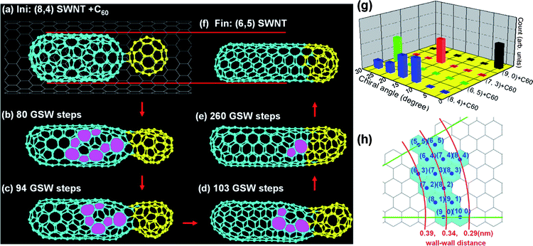 | ||
| Fig. 2 Panels (a–f) are snapshots taken in the fusion of a (8,4) C180 inner tube and a C60. The final inner tube (f) has smaller diameter than that of the original one (a). (g) The chiral-angle distributions of the inner tubes which are formed in the fusion of different C180 inner tubes with C60. (h) The wall–wall distances between various inner tubes and the outer (18,0) tube. | ||
Except for the large diameter (8,4) C180 inner tube, the other three inner tubes, (9,0), (7,3) and (6,5), explored in this study have well fitted wall–wall distances with the (18,0) outer tube, which are 0.352 nm, 0.331nm and 0.355nm, respectively. As a consequence, every trajectory (see Table S2†) results in a tube with the exact same chirality as the original one (Fig. 2g). The apparent contrast with the results shown in Fig. 1 indicates that an inner tube with a chirality identified stem of 2 nm or longer is very robust and its chirality is very hard to change unless its wall–wall distance with the outer tube is far from the equilibrium distance, 0.34 nm.
3.3 The competition between two short tubes: C120 + C120
Here we focus on the fusion of two short inner tubes, C120 + C120. Fig. 3a–e are representative snapshots during the fusion of two (9,0) C120 tubes. At the initial elongation stage, the inner tube on the right side becomes very defective and then it turns into a (5,5) tube (Fig. 3a→b→c). A intra-tube junction, which contains a few 5|7s and connects the (9,0) tube on the left and the newly formed (5,5) tube on the right, is formed during the process (Fig. 3c). In the following simulation, the 5|7 pairs around the intra-tube junction gradually glide to the left side of the inner tube and disappear into the tube cap eventually (Fig. 3c→d→e). The full EDKMC trajectory costs about 2000 GSW steps, which is about one order of magnitude slower than the fusion of C120 + C60. The long trajectory implies that the fusion of two short tubes into a single chirality one is very difficult and the diffusion of a tube–tube junction is very slow.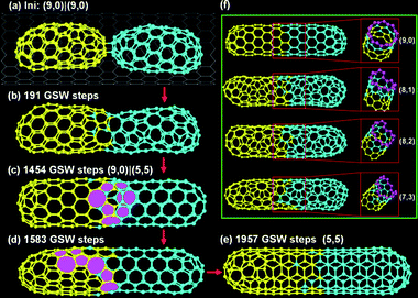 | ||
| Fig. 3 (a–e) Snapshots in the fusion of two (9,0) C120 inner tubes into a (5,5) C240 tube. (f) Four different C240 tubes observed in different trajectories. | ||
It's important to note that the final tubes can be very diverse. Beside the before mentioned (5,5) tube, other chiral tubes, for example (9,0), (8,1), (8,2), (7,3) tubes, have been observed in EDKMC trajectories (see Fig. 3f).
3.4 The competition between a longer inner tube and a shorter inner tube: C180 + C120
From the results presented above, we can conclude that these very short C120 tubes cannot maintain their chiralities during the fusions of C120 + C60 or C120 + C120 but the longer C180 tubes are very robust. So it's very natural to suspect that a longer tube is going to beat a short one to inherit its gene, the chirality, in the fusion of C180 + C120. Fig. 4 visibly shows such a trend, the stem of the (9,0) tube becomes longer and longer and eventually dominates the final tube in the coalescence of a (9,0) C180 tube + (6,5) C120 tube. This indicates that the tube length is the most critical parameter in the tube–tube fusion.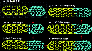 | ||
| Fig. 4 The fusion of a (9,0) C180 tube + (6,5) C120 tube. | ||
3.5 The competition between two longer tubes: C180 + C180
So far, we can conclude that it's very hard to change the chirality of an inner tube whose chirality identified stem is longer than 2 nm. Therefore, what will happen if two long C180 inner tubes meet each other and fuse into one? The fusion process of a (5,5) C180 tube and a (9,0) C180 tube is shown in Fig. 5. A tube–tube neck which has nearly same diameter as the original tubes is formed in between after ∼500 GSW annealing steps (a→b→c). An intra-molecular ring of defects that is composed of a few 5|7 pairs can be identified around the neck area (c). The position of the ring does not change in the following long EDKMC simulation (up to 3000 GSW steps) though the arrangement of the 5|7s becomes different (c→d). The robusiticity of the two inner tubes results in a stable intra-tube junction. To link two different SWNTs into one, such a junction is inevitable. Similar intra-tube junctions are seen in other trajectories. As shown in Fig. 5f, the junctions of (9,1)|(9,0), (7,3)|(9,0) and (6,4)|(9,0) contain 1, 3 and 4 5|7 pairs, respectively. | ||
| Fig. 5 (a–d) Some typical snapshots during the coalescence of a (9,0) C180 inner tube and a (5,0) C180 inner tube. (e) The perspective view of the tube–tube junction. (f) Several other tube–tube junctions formed in the coalescence of a (9,0) C180 tube and a few other C180 tubes. (g) The number of 5|7 pairs at the tube–tube junction as a function of chiral angle difference between two tubes. | ||
4. Discussion
4.1 The intra-tube junction as a rolled up graphene grain boundary
As shown in the perspective view of the intra-tube junction between a (5,5) tube and a (9,0) tube (Fig. 5e), the 5|7 pairs form a ring of defects in a regular manner, the pentagon of a 5|7 pair contacts with the heptagon of a neighboring pair or pentagons and heptagons appear alternatively along the tube circumference. The novel ring formation is a consequence of minimizing the junction's formation energy. Recent study in graphene grain boundaries reveals that a linear arrangement of 5|7 pairs minimizes the boundary formation energy because of the cancellation of the compression and tension strains around a 5|7 pair.43 A carbon nanotube can be viewed as rolled up graphene and therefore the ring of 5|7s can be viewed as a rolled up graphene grain boundary.Fig. 5g shows the number of 5|7 pairs of an intra-tube junction as a function of the chiral angle difference between the two tubes. A clear linear relationship, N5|7 ∼ Δθ, is presented. Such behavior is a bit surprising since it has been theoretically proved that only one pentagon and one heptagon are sufficient to connect two arbitrary SWNTs (Fig. 6a→b).44,45 It's important to note that the previous theory allows the hybrid tube wall to turn a sharp angle at the junction (Fig. 6b), while a peapod derived inner tube is constrained inside a straight outer tube and thus has to maintain its straightness at the junction (Fig. 6d). So the previous ideal model of tube-tube junction can't be applied to understand the formation of peapod derived DWNTs. Here we propose another model, that the intra-tube junction should be viewed as a rolled up graphene grain boundary to explain the multiple 5|7 formation. In that model, a straight graphene nanoribbon (GNR) is cut along a direction perpendicular to the grain boundary (Fig. 6c) and then folded into a tube (Fig. 6c→d). The straight GNR edges ensure the straightness of the folded tube (Fig. 6d).
 | ||
| Fig. 6 Two arbitrary tubes can be connected by a pentagon and a heptagon. As an example, a (9,0) tube and a (5,5) tube are connected by a separated pentagon and heptagon (a–b) but the tube wall turns a sharp angle of ∼30 degree at the intra-tube junction (a). (c)→(d) Rolling a graphene grain boundary into a straight tube with an intra-tube junction. The grain boundary contains multiple 5|7 pairs forming a ring of topological defects (e). | ||
As has been discussed in detail in recent literature, a 5|7 in graphene is an edge dislocation in a 2D hexagonal lattice and the magnitude of its Burgers vector is b = 0.246 nm.46 In a graphene grain boundary, the requirement of formation energy minimization aligns all the 5|7 pairs linearly. So the mismatch angle between both sides can be estimated by the following equation:47
| sin(Δθ) = b/d | (1) |
| N5|7 = l/d = l × sin(Δθ)/b ∼ l × Δθ/b | (2) |
4.2 Experimental observation of intra-tube junctions
High-resolution transmission electron microscopy (HRTEM) measurements were taken to examine the coalescence behaviors of inner tubes within a confined space. The peapod derived DWNTs were prepared by thermally treating peapods at 1700 and 1800 °C in argon (details shown in Experimental Method section†). There is no distinctive change in the bundled structure of peapod-grown DWNTs (Fig. 7a) because the hosting SWNTs are structurally stable up to 2000 °C. In the HRTEM images of DWNTs, the coalescence of short inner tubes with adjacent fullerene (Fig. 7b), the coalescence of adjacent short tubes (Fig. 7c) and the formation of intra-tube junctions (Fig. 7d) are clearly seen. | ||
| Fig. 7 Transmission electron microscope images of peapod-grown DWNTs that are grown by thermally treating peapods at 1700 °C in argon using a graphite furnace at (a) low- and (b–d) high-resolutions. | ||
Although the pentagons and heptagons can not be identified near the intra-tube junctions because of the resolution limitation of our TEM, the evidence of the intra-tube junction is solid. Thus the experimental observation presents the validity of the theoretical study.
4.3 A growth model of peapod-grown DWNTs
A model of peapod derived DWNTs is shown in Fig. 8 to summarize the study. At the initial nucleation stage, the simultaneous coalescence of many fullerenes in a long carbon peapods results in many isolated short inner tubes of different chiralities inside (Fig. 8 a→b). These short inner tubes grow longer and longer by exhausting neighboring fullerenes (Fig. 8 b→c). Once fullerenes between two inner tubes are exhausted, the two tubes contact each other directly and then fuse into one straight tube that contains a stable intra-tube junction (Fig. 8d) The final long inner tube which is formed by the fusion of many short ones possesses many intra-tube junctions (Fig. 8 e). | ||
| Fig. 8 (a–e) A scheme of the intra-tube junction formation in the inner wall of a peapod derived DWNT. The color of an inner tube of the inner tube section represents its chirality. | ||
5. Conclusions
In conclusion, two inner tube elongation processes in the formation of peapod derived DWNTs are identified by the EDKMC simulation: (i) fusion of tube + C60 and (ii) coalescence of tube + tube. In both processes, only the chirality of very short inner tubes whose stem length is less than 2 nm might be changed and a long inner tube shows its extreme robusticity because of the confinement effect of the outer tube. Our study predicates that the fusion of two long inner tubes must result in a robust intra-tube junction. The formation of the intra-tube junction, which can be viewed as a folded graphene grain boundary, contains multiple pentagon|heptagon pairs (5|7) forming a defect ring. The number of the 5|7s in a junction is proportional to the product of the inner tube's chiral difference and the length of the inner tube circumference. Beyond this, careful HRTEM imaging on peapod derived DWNT samples clearly represents both coalescence processes and shows solid evidence of the intra-tube junction.Acknowledgements
We acknowledge the financial support received from Hong Kong Polytechnic University (A-PJ50, A-PH93, A-PD1U). YAK and ME acknowledge the support from the Regional Innovation Cluster Program of Nagano from the MEXT of Japan.Notes and references
- B. W. Smith, M. Monthioux and D. E. Luzzi, Nature, 1998, 396, 323–324 CrossRef CAS.
- B. W. Smith, M. Monthioux and D. E. Luzzi, Chem. Phys. Lett., 1999, 315, 31–36 CrossRef CAS.
- B. W. Smith and D. E. Luzzi, Chem. Phys. Lett., 2000, 321, 169–174 CrossRef CAS.
- H. Kataura, Y. Maniwa, T. Kodama, K. Kikuchi, K. Hirahara, K. Suenaga, S. Iijima, S. Suzuki, Y. Achiba and W. Kräschmer, Synth. Met., 2001, 121, 1195–1196 CrossRef CAS.
- X. Liu, T. Pichler, M. Knupfer, M. S. Golden, J. Fink, H. Kataura, Y. Achiba, K. Hirahara and S. Iijima, Phys. Rev. B: Condens. Matter, 2002, 65, 045419 CrossRef.
- M. Yudasaka, K. Ajima, K. Suenaga, T. Ichihashi, A. Hashimoto and S. Iijima, Chem. Phys. Lett., 2003, 380, 42–46 CrossRef CAS.
- H. Kuzmany, R. Pfeiffer, C. Kramberger, T. Pichler, X. Liu, M. Knupfer, J. Fink, H. Kataura, Y. Achiba, B. W. Smith and D. E. Luzzi, Appl. Phys. A: Mater. Sci. Process., 2003, 76, 449–456 CrossRef CAS.
- S. Bandow, M. Takizawa, K. Hirahara, M. Yudasaka and S. Iijima, Chem. Phys. Lett., 2001, 337, 48–54 CrossRef CAS.
- Y. Fujita, N. Niwa, S. Bandow and S. Iijima, Appl. Phys. A: Mater. Sci. Process., 2006, 85, 307–310 CrossRef CAS.
- R. Pfeiffer, T. Pichler, Y. Kim and H. Kuzmany, Top. Appl. Phys., 2008, 111, 495 CrossRef CAS.
- T. Okazaki, S. Bandow, G. Tamura, Y. Fujita, K. Iakoubovskii, S. Kazaoui, N. Minami, T. Saito, K. Suenaga and S. Iijima, Phys. Rev. B: Condens. Matter Mater. Phys., 2006, 74, 153404 CrossRef.
- M. Koshino, Y. Niimi, E. Nakamura, H. Kataura, T. Okazaki, K. Suenaga and S. Iijima, Nat. Chem., 2010, 2, 117–124 CrossRef CAS.
- E. Hernandez, V. Meunier, B. W. Smith, R. Rurali, H. Terrones, M. Buongiorno Nardelli, M. Terrones, D. E. Luzzi and J. C. Charlier, Nano Lett., 2003, 3, 1037–1042 CrossRef CAS.
- R. Pfeiffer, F. Simon, H. Kuzmany and V. N. Popov, Phys. Rev. B: Condens. Matter Mater. Phys., 2005, 72, 161404 CrossRef.
- R. Pfeiffer, M. Holzweber, H. Peterlik, H. Kuzmany, Z. Liu, K. Suenaga and H. Kataura, Nano Lett., 2007, 7, 2428–2434 CrossRef CAS.
- H. Kuzmany, W. Plank, R. Pfeiffer and F. Simon, J. Raman Spectrosc., 2008, 39, 134–140 CrossRef CAS.
- G. Ning, N. Kishi, H. Okimoto, M. Shiraishi, T. Sugai and H. Shinohara, J. Phys. Chem. C, 2007, 111, 14652–14657 CrossRef CAS.
- G. G. Samsonidze, R. Saito, N. Kobayashi, A. Gruneis, J. Jiang, A. Jorio, S. G. Chou, G. Dresselhaus and M. S. Dresselhaus, Appl. Phys. Lett., 2004, 85, 5703–5705 CrossRef CAS.
- H. Muramatsu, T. Hayashi, Y. A. Kim, D. Shimamoto, M. Endo, V. Meunier, B. G. Sumpter, M. Terrones and M. S. Dresselhaus, Small, 2009, 5, 2678–2682 CrossRef CAS.
- D. Shimamoto, H. Muramatsu, T. Hayashi, Y. A. Kim, M. Endo, J. S. Park, R. Saito, M. Terrones and M. S. Dresselhaus, Appl. Phys. Lett., 2009, 94, 083106–083103 CrossRef.
- F. Villalpando-Paez, H. Muramatsu, Y. A. Kim, H. Farhat, M. Endo, M. Terrones and M. S. Dresselhaus, Nanoscale, 2010, 2, 406–411 RSC.
- F. Villalpando-Paez, L. G. Moura, C. Fantini, H. Muramatsu, T. Hayashi, Y. A. Kim, M. Endo, M. Terrones, M. A. Pimenta and M. S. Dresselhaus, Phys. Rev. B: Condens. Matter Mater. Phys., 2010, 82, 155416 CrossRef.
- S. Bandow, T. Hiraoka, T. Yumura, K. Hirahara, H. Shinohara and S. Iijima, Chem. Phys. Lett., 2004, 384, 320–325 CrossRef CAS.
- J. H. Warner, M. H. Rümmeli, A. Bachmatiuk and B. Büchner, Phys. Rev. B: Condens. Matter Mater. Phys., 2010, 81, 155419 CrossRef.
- H. Muramatsu, D. Shimamoto, T. Hayashi, Y. A. Kim, M. Terrones, M. Endo and M. S. Dresselhaus, Adv. Mater., 2011, 23, 1761–1764 CrossRef CAS.
- H. Su, R. J. Nielsen, A. C. T. van Duin and W. A. Goddard III, Phys. Rev. B: Condens. Matter Mater. Phys., 2007, 75, 134107 CrossRef.
- I. Suarez-Martinez, P. J. Higginbottom and N. A. Marks, Carbon, 2010, 48, 3592–3598 CrossRef CAS.
- Y. Shibuta and S. Maruyama, Heat Transfer—Asian Research, 2006, 35, 254–264 Search PubMed.
- X. Li, W. Yang and B. Liu, Nano Lett., 2007, 7, 3709–3715 CrossRef CAS.
- A. Trave, F. J. Ribeiro, S. G. Louie and M. L. Cohen, Phys. Rev. B: Condens. Matter Mater. Phys., 2004, 70, 205418 CrossRef.
- V. Zólyomi, J. Koltai, D. Visontai, L. Oroszlány, Á. Rusznyák, I. László and J. Kürti, Phys. Rev. B: Condens. Matter Mater. Phys., 2010, 82, 195423 CrossRef.
- A. J. Stone and D. J. Wales, Chem. Phys. Lett., 1986, 128, 501–503 CrossRef CAS.
- Y. Zhao, B. I. Yakobson and R. E. Smalley, Phys. Rev. Lett., 2002, 88, 185501 CrossRef.
- Y. Zhao, R. E. Smalley and B. I. Yakobson, Phys. Rev. B: Condens. Matter, 2002, 66, 195409 CrossRef.
- Y. Zhao, Y. Lin and B. I. Yakobson, Phys. Rev. B: Condens. Matter, 2003, 68, 233403 CrossRef.
- S. Han, M. Yoon, S. Berber, N. Park, E. Osawa, J. Ihm and D. Tománek, Phys. Rev. B: Condens. Matter Mater. Phys., 2004, 70, 113402 CrossRef.
- I.-H. Lee, S. Jun, H. Kim, S. Y. Kim and Y. Lee, Appl. Phys. Lett., 2006, 88, 011913–011913 CrossRef.
- F. Ding, Z. W. Xu, B. I. Yakobson, R. J. Young, I. A. Kinloch, S. Cui, L. Deng, P. Puech and M. Monthioux, Phys. Rev. B: Condens. Matter Mater. Phys., 2010, 82, 041403 CrossRef.
- F. Ding, K. Jiao, Y. Lin and B. I. Yakobson, Nano Lett., 2007, 7, 681–684 CrossRef CAS.
- F. Ding, K. Jiao, M. Wu and B. I. Yakobson, Phys. Rev. Lett., 2007, 98, 075503 CrossRef.
- J. Y. Huang, F. Ding, K. Jiao and B. I. Yakobson, Phys. Rev. Lett., 2007, 99, 175503 CrossRef CAS.
- K. Hirahara, M. Kociak, S. Bandow, T. Nakahira, K. Itoh, Y. Saito and S. Iijima, Phys. Rev. B: Condens. Matter Mater. Phys., 2006, 73, 195420 CrossRef.
- B. I. Yakobson and F. Ding, ACS Nano, 2011, 5, 1569–1574 CrossRef CAS.
- R. Saito, G. Dresselhaus and M. S. Dresselhaus, Phy. Rev. B, 2044, 1996, 53 Search PubMed.
- S. Melchor and J. A. Dobado, J. Chem. Inf. Model., 2004, 44, 1639 CrossRef CAS.
- B. I. Yakobson, Appl. Phys. Lett., 1998, 72, 918–920 CrossRef.
- O. V. Yazyev and S. G. Louie, Phys. Rev. B: Condens. Matter Mater. Phys., 2010, 81, 195420 CrossRef.
Footnote |
| † Electronic supplementary information (ESI) available: experimental details, two tables about the statistics of final inner tubes generated by the EDKMC simulation. See DOI: 10.1039/c1nr10889a |
| This journal is © The Royal Society of Chemistry 2012 |