Ferrofluid mediated nanocytometry†
Ayse Rezzan
Kose
a and
Hur
Koser
*b
aSchool of Engineering and Applied Science, Yale University, 15 Prospect St., Becton Center, Room 608, New Haven, CT 06520-8267, USA. E-mail: ayse.kose@yale.edu; Fax: +1 (203) 432-6420; Tel: +1 (203) 432-8573
bSchool of Engineering and Applied Science, Yale University, 15 Prospect St., Becton Center, Room 507, New Haven, CT 06520-8267, USA. E-mail: hur.koser@yale.edu; Fax: +1 (203) 432-6420; Tel: +1 (203) 432-9629
First published on 11th November 2011
Abstract
We present a low-cost, flow-through nanocytometer that utilizes a colloidal suspension of non-functionalized magnetic nanoparticles for label-free manipulation and separation of microparticles. Our size-based separation is mediated by angular momentum transfer from magnetically excited ferrofluid particles to microparticles. The nanocytometer is capable of rapidly sorting and focusing two or more species, with up to 99% separation efficiency and a throughput of 3 × 10⁴ particles/s per mm2 of channel cross-section. The device is readily scalable and applicable to live cell sorting with biocompatible ferrofluids, offering competitive cytometer performance in a simple and inexpensive package.
Introduction
Separating and sorting microparticles and live cells rapidly and efficiently is crucial in many clinical, diagnostic and pharmaceutical settings. In cancer research and therapy, for instance, there is a considerable need for isolation and detection of rare circulating tumor cells in blood for disease prognosis.1–7 Similarly, the capability to conduct rapid blood cell counts is vital for monitoring the progression of many diseases.8 In cellular therapy, effective selection and purification of stem cells holds great promise in treatment of genetic conditions, hematological disease and immunodeficiency.9,10 Most standard techniques in these contexts involve expensive equipment and require time consuming protocols, frequently with manual labor-intensive steps.11 Therefore, there is a substantial need for such separation and sorting to be accomplished within low-cost, high throughput and high efficiency cytometers in a label-free fashion with minimal labor.The pressing need for the development of alternative separation techniques has led to a proliferation of new platforms.12–21 These new separation schemes generally fall into two broad categories: techniques that utilize alternative labels, including immunomagnetic separation,14 and label-free techniques such as dielectrophoresis (DEP) and hydrodynamic separation that rely on physical differences between cells and particles (e.g., size, density, shape, morphology or dielectric properties). Some of the currently available cell separation technologies and their performance metrics are summarized in Table 1. Fluorescence activated cellular sorting (FACS) is one of the most widely employed systems due to its high accuracy and versatility.12,22–28 However, the combination of precision flow systems with delicate laser optics makes FACS a complex, expensive technology to acquire (∼$250,000). Additionally, the need to rely on trained personnel to run assays on FACS renders it expensive to use and maintain, as well. Immunomagnetic separation, on the other hand, allows for the use of cheap permanent magnets to separate target cellsviaantibody-functionalized magnetic microbead labels.14,16 This approach offers high throughput and reduced cost, but still relies on manual labor steps.
| Separation Mode | Purity(%) | Throughtput | Label | Cost ($) setup/consumables | Typical assay run-time | |
|---|---|---|---|---|---|---|
| a Reports from company directly. | ||||||
| FACS 11,12 | Flow/electrostatic actuation | >88 | ∼104cells s−1 | Yes,fluo | >250,000/1000a | ∼1 h |
| Immunomagnetic, batch14,15 | Batch/magnetic actuation of label | >70 | 106cells s−1 | Yes,magnetic | 390/320a | ∼1 h |
| Immunomagnetic, flow14,15 | Flow/magnetic actuation of label | >99 | 103cells s−1 | Yes,magnetic | ∼1000/300 (estimated) | ∼1 h |
| Hydrodynamic17 | Flow/hydrodynamic forces | 99 | ∼3 cells s−1 | No | ∼100/100 (estimated) | ∼1 h (for 1μl blood) |
| Dielectrophoresis 19 | Batch or flow/electrodynamic actuation | 95 | ∼3 × 10³cells s−1 | No | ∼1000/1 (estimated) | 10 min |
| Ferro-microfluidic21 | Batch or flow; ferrohydrodynamic actuation | 98 | ∼3 × 10⁴ particles/s mm−2 | No | ∼100/1 | ∼1 min |
Advances in micro- and nano-fabrication technologies have recently enabled the realization of miniaturized sorters that achieve particle manipulation with reduced manual labor using fluidic, electric, and magnetic forces.29–35 Replacing conventional cell sorting devices with micro systems also increases analytic sensitivity,36 though typically at the expense of throughput. For instance, Davis et al. employ a matrix of silicon microposts to hydrodynamically fractionate blood cells.17 While highly accurate in the analysis of small samples (∼ 1 μl), the device requires high-resolution microfabrication and is prone to clogging. DEP is a widely explored, alternative technique that exploits electric fields for cellular manipulation and sorting; the downside of this technique is the sensitivity of the system to flow and the buffer's electrical properties.19,37 Moreover, the use of large electric fields and their gradients in DEP may polarize cells and potentially damage or otherwise interfere with cellular functions.
Magnetophoresis is an alternative to navigate around the challenges of using high electric fields within conductive buffer solutions. Magnetic fields are typically not hazardous to cells and are not significantly affected by the ionic content or the pH levels of the solution. They can be applied externally, eliminating the need for physical contact between the field source and the analyte.38,39 Besides their common use in immunomagnetic separation, magnetic fields can manipulate cells and microparticles via label-free, negative magnetophoresis, as well.21,40 In this approach, magnetic nanoparticles within a ferrofluid medium are attracted towards higher magnetic field regions, thereby effectively displacing and guiding non-magnetic objects away from field sources.41 Displaced objects experience magnetic repulsion forces in proportion to their volumes, making size-based separation possible in flow-through devices. The source of magnetic fields in such separators has traditionally been permanent magnets.34,35 To obtain high separation accuracy, these platforms require a very tight focusing of the input sample stream, resulting in low throughput.
In a recent study, we reported a new micro-separation and sorting platform that utilizes a low-cost electrode substrate to create locally programmable magnetic fields within a nano-colloidal suspension medium.21 We demonstrated the proof of principle for the sorting mechanism in a closed microfluidic channel with no external flow, and elucidated the physical mechanism of cell manipulation based on size, shape and elasticity.
In this paper, we demonstrate a flow-through, ferrofluid-mediated nano-cytometer that continuously separates, sorts and focuses micro-particles based on size. Our technique utilizes inexpensive materials and achieves label-free and labor-free separation. The nanocytometer device delivers over 98% sample purity and high throughput per unit cross-section (>3 × 10⁴ particles/s per mm2), rendering it a practical candidate for clinical cytometry.
At this early stage, we used microspheres to demonstrate the capability of our technology and study the separation and sorting mechanism in the presence of flow. We elucidate in detail the flow effects, such as the flow-induced hydrodynamic shear on the effectiveness of the ferrofluid-based separation. We believe that once these issues are understood and devices are characterized, separating and sorting live cells is possible, as we demonstrated in a prior publication using our initial prototype platform with no flow.21 Our technology is still clinically relevant even if the separation is confined to microspheres only, as microspheres of different sizes can be functionalized (i.e., labeled) to separate and sort protein, DNA, virus, bacterial or cellular targets from complex mixtures.
Materials and methods
Microfluidic device design and principle
The nanocytometer is comprised of a micro-molded fluidic channel within an elastic material bonded over an inexpensive printed circuit board (PCB, The Bergquist Company, Chanhassen, MN, USA) with a single layer of electrodes patterned via low-resolution lithography (Fig. 1a). The device features a polydimethylsiloxane (PDMS, Sylgard 184, from Dow Corning, Midland, MI, USA) microfluidic channel that incorporates a separation chamber (2.7 cm long, either 1200 μm or 1800 μm wide, and 20 μm deep) between three or four sets of inlets and outlets. The electrodes run parallel to the length of the microchannel, such that ferrofluid-mediated magnetic separation takes place orthogonal to the flow direction (Fig. 1b). The channel is first washed with 1% Triton-X solution to prevent unspecific particle attachment. A stream of microspheres of various sizes suspended in a ferrofluid (EMG700, Ferrotec Corporation, Santa Clara, CA, USA) is hydrodynamically focused over the gap between adjacent electrodes. The physical mechanism of microparticle manipulation was described in a previous report.21 To recap briefly: the underlying electrodes carry currents in quadrature (90° phase difference between adjacent electrodes) to generate a locally rotating, non-uniform magnetic field within the channel. The spatial gradient of this traveling field induces a repulsive force on the non-magnetic microparticles in ferrofluid, tending to push them towards the channel ceiling and focus them over the gaps between electrodes. The magnetic excitation also induces nanoparticle rotation, which, in turn, imparts a torque on the microspheres (Fig. 2a), tending to roll them along the channel ceiling. For a microparticle of a given size, shape and elasticity, magnetic force effects dominate below a critical excitation frequency (fc) and result in trapping between electrodes. Beyond fc, torque dominates and the microparticles continuously roll over the channel ceiling in the opposite direction of the traveling field.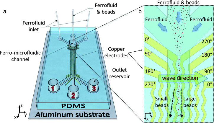 | ||
| Fig. 1 Ferro-microfluidic particle sorting platform. (a) The device consists of a poly-dimethylsiloxane (PDMS) channel over copper electrodes. Microspheres, suspended in ferrofluid, are introduced from the center inlet and hydrodynamically focused by the ferrofluid flow from the side inlets. (b) Top view of the beginning of the separation channel. The electrodes are connected in quadrature, with a 90° phase difference to generate a magnetic field pattern that travels along +y-axis within the separation chamber, rolling the microspheres in the opposite direction. With the appropriate excitation frequency, the stream of larger particles become trapped and focused between the center electrodes, while smaller particles continuously move away. At the end of the separation channel, particles with different sizes reach different outlet reservoirs. | ||
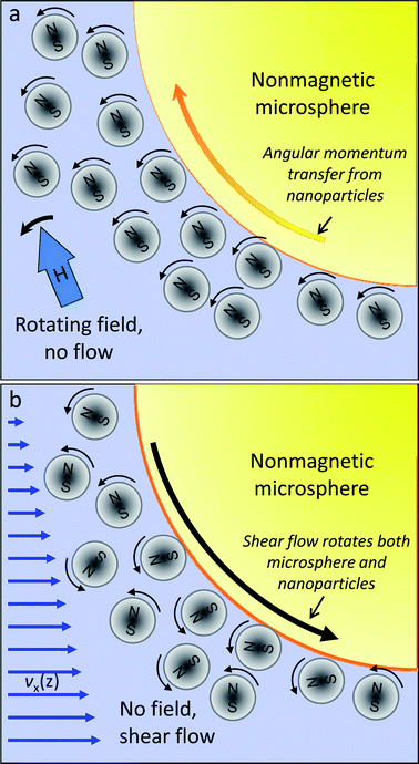 | ||
| Fig. 2 Rotational interactions between nanoparticles and microspheres. (a) Under the influence of a magnetic field rotating within the y–z plane, most magnetite nanoparticles in the EMG700 ferrofluid get aligned with the field and begin whirling. Nanoparticles proximal to the surface of a nonmagnetic microsphere experience increased rotational drag, which results in partial angular momentum transfer and causes the microsphere to roll in the opposite direction. (b) On the other hand, presence of shear flow near the channel ceiling causes both nanoparticles and microspheres to spin counter-clockwise within the x–z plane with similar angular velocities. The surface velocity of the microsphere is much faster and opposite to that of the proximal nanoparticles, and continuously disrupts their rotation. At high enough shear rates, this disruption also begins to interfere with the angular momentum transfer due to the rotating field in the orthogonal plane. | ||
With uniform electrode spacing, particle manipulation in bio-ferrofluidic devices is limited to the separation of one microparticle or cell species from others. With varying electrode gaps, the balance between magnetic force and torque effects can be altered locally, and simultaneous sorting of more than two species becomes possible at a given excitation frequency. Specifically, larger electrode gaps can progressively trap smaller microparticles at a fixed frequency; hence, a gradient of electrode spacing may sort microparticles in descending size order. We proposed this theoretical possibility in our prior work;21 here, we experimentally demonstrate this sorting functionality in a simple, low-cost and disposable nanocytometer. One significant advantage that our approach offers is the potential for discrete sorting, with each species sorted and tightly focused onto a separate particle stream. This capability renders our bio-ferrofluidic nanocytometer highly practical simultaneously as a potential separator, sorter and counter of multiple microparticle species in parallel.
Flow considerations
There are two effects that limit the maximum flow rate that can be sustained while achieving complete separation with this nanocytometer: (i) the time it takes for the smallest (i.e., the slowest) microparticle to be sorted into its own stream; and (ii) the maximum shear rate that can be sustained without substantially disturbing the angular momentum transfer from the magnetic nanoparticles to the non-magnetic microparticles. The first consideration leads to a minimum residence time requirement of just under 30 s as the smallest microspheres (2.2 μm) are separated from the main stream of particles by one electrode spacing (500 μm, traversed at approximately 20 μm s−1 with 7 A peak-to-peak excitation). This limitation on flow rate is easily mitigated by choosing the length of the separation chamber long enough to ensure that minimum residence time is achieved. The second limitation on flow rate is more stringent. Normally, the angular momentum transfer from the magnetic nanoparticles to the nonmagnetic microspheres (as depicted in Fig. 2a) should be dominant over magnetic repulsion forces above the critical excitation frequency, resulting in net microparticle travel along the channel width across the electrodes. With externally imposed flow, however, the shear rate in the vicinity of the channel ceiling begins to lead to the rotation of both magnetic nanoparticles and the non-magnetic microspheres around the y-axis (Fig. 2b). In this case, nanoparticle rotation due to shear creates extra friction for microsphere rotation, and impedes effective angular momentum transfer to the microspheres when the magnetic excitation is turned on. Physically, this situation may be modeled by incorporating a multiplicative slip factor that reduces the total torque imparted on the microsphere.21 As the shear rate goes up, the slip factor gradually goes down from 1 towards 0, and magnetic force effects on microparticles begin to dominate over torque transfer. As a result, the critical frequency increases with increasing shear, up to a point beyond which torque transfer is too inefficient to matter at all. In general, field-induced nanoparticle rotation has to dominate over shear-related friction effects in order to achieve microparticle separation within the nanocytometer. This requirement means that the input current levels have be to large enough and the local shear near the channel ceiling small enough to achieve reliable performance. Empirically, we determined that a shear rate of 357 s−1 near the center of the channel ceiling (i.e., 1.7 μl min−1 flow through the 1200 μm wide and 20 μm deep channel) was the highest acceptable hydrodynamic disturbance while still achieving good microparticle separation under 7 App current excitation. At this flow rate, the critical frequencies for three different sizes of polystyrene microparticles (2.2 μm, 4.8 μm, and 9.9 μm diameter; all with a density of 1.05 g cm−3) were approximately 500 Hz, 1500 Hz and 2500 Hz, respectively. For comparison, fc values for the three sets of particles in the absence of flow were lower – specifically, 80 Hz, 900 Hz and 1800 Hz, respectively.Experimental results
Binary separation
Once flow rate effects were elucidated, we proceeded with sorting binary microparticle mixtures based on size. In one experiment, 2.2 μm and 4.8 μm fluorescent microspheres (1![[thin space (1/6-em)]](https://www.rsc.org/images/entities/char_2009.gif) :1 ratio, 1.4 × 10⁶ particles/ml in total) was introduced to the separation chamber from the center inlet (at 0.3 μl min−1), while bare ferrofluid was injected from the side inlets (at 0.7 μl min−1 each) to hydrodynamically focus the microparticles into the center electrode spacing. Once subjected to the traveling magnetic excitation (generated via 7 App alternating currents at 1500 Hz), the 2.2 μm particles immediately deviated from the center line and began to move towards outlet 1, while the 4.8 μm particles remained focused in single file within the center stream until they reached outlet 2 (supplementary video†). Outlet 3 was designated as a negative control to only collect bare ferrofluid.
:1 ratio, 1.4 × 10⁶ particles/ml in total) was introduced to the separation chamber from the center inlet (at 0.3 μl min−1), while bare ferrofluid was injected from the side inlets (at 0.7 μl min−1 each) to hydrodynamically focus the microparticles into the center electrode spacing. Once subjected to the traveling magnetic excitation (generated via 7 App alternating currents at 1500 Hz), the 2.2 μm particles immediately deviated from the center line and began to move towards outlet 1, while the 4.8 μm particles remained focused in single file within the center stream until they reached outlet 2 (supplementary video†). Outlet 3 was designated as a negative control to only collect bare ferrofluid.
Fig. 3, top row depicts a series of three fluorescent microscopy image snapshots obtained during the course of the experiment from the inlet, center and outlet regions of the device, respectively. These images demonstrate the progression of microparticle separation as they are dragged downstream. The experiments were run multiple times with comparable results. Fig. 3, bottom row displays the corresponding particle counts (as normalized probability density functions) across the width of the separation channel, as determined from images accumulated over the three regions for at least 10 s. At the end of a given run, samples from both active outlets (a total of 10 samples from each outlet, 10 μl each) were pipetted onto microscope slides, and the number of microparticles in each droplet was counted using ImageJ.42 Particle counts were then averaged. Fig. 4 depicts the images taken from the inlet and the two active outlets, together with the corresponding sample purities. As expected, we did not find any microparticles in outlet 3 (control). We found that 98.2 ± 0.4% of the particles collected in outlet 1 were 2.2 μm and 86.3 ± 3.8% of particles collected in outlet 2 were 4.8 μm. The error bars represent the ± standard deviation in the independent sampling of the output wells (n = 10) at different times during the experiment. The lower purity value obtained in outlet 2 resulted in part from the electrostatic attraction of 2.2 μm microspheres to the larger particles. We define separation efficiency as the ratio of the number of target microparticles collected in their corresponding outlet to their total number in all outlets. Under this definition, the separation efficiency for 2.2 μm and 4.8 μm particles was 99% and 77%, respectively.
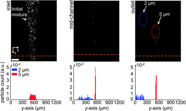 | ||
| Fig. 3 Binary separation of 2.2 μm and 4.8 μm microspheres (7 App, 1500 Hz). The microfluidic device features a PDMS channel 20 μm high, 2.7 cm long and 1200 μm wide. The electrodes are 210 μm wide and 220 μm apart. (Top) Fluorescence microscopy snapshots of the channel inlet, center and outlet regions from above, depicting 2.2 μm particles deviating from the center line and 4.8 μm particles being focused at the center spacing. Microspheres of different sizes eventually reach different outlets. (Bottom) Probability density functions (PDF's) associated with the y-location of each particle size as the microspheres crossed the depicted green dashed line at the beginning, center and end of the separation channel. 4.8 μm microspheres are tightly focused in single-file at the center stream, while 2.2 μm microspheres are continuously cleared. Scale bar: 200 μm. | ||
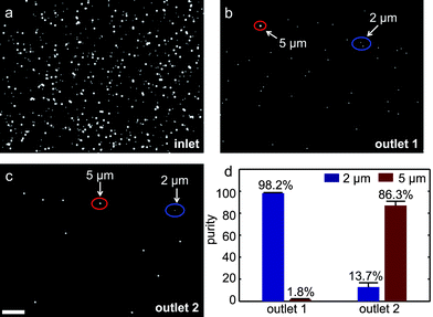 | ||
| Fig. 4 Microscope images of samples obtained from the initial particle mixture (a), as well as the two active outlets of the binary sorter (b) and (c). (d) Purity of the separated samples. 98.2 ± 0.4% of the particles collected from outlet 1 are 2.2 μm, while 86.3 ± 3.8% of the particles collected from outlet 2 are 4.8 μm particles. Scale bar: 100 μm. | ||
Ternary separation
In another experiment, we used a wider channel (1800 μm) with four sets of inlets and outlets, together with a linear gradient of electrode spacing to conduct discrete particle sorting between three different microparticle sizes simultaneously. The microparticle mixture (2.2 μm, 4.8 μm and 9.9 μm microspheres, suspended in ferrofluid at 2.56 × 10⁶ particles/ml) was introduced to the separation chamber from a side inlet (at 0.4 μl min−1), while bare ferrofluid was injected from the central two inlets at 0.8 μl min−1 (total flow rate: 2.4 μl min−1). Under these flow conditions, the microparticle mixture was hydrodynamically focused over the smallest electrode gap (100 μm) at the beginning of the sorting chamber. As depicted in Fig. 5, the magnetic field excitation (8 App, 1200 Hz) quickly sorted the microspheres over the three electrode gaps (100 μm, 200 μm and 300 μm) in descending size order and focused each stream of particles into a tight progression (supplementary video†). Purity levels at the three active outlets were: 100% for 2.2 μm, 91 ± 0.8% for 4.8 μm, and 92 ± 0.5% for 9.9 μm microsphere samples. The corresponding separation efficiencies were 99.4 ± 0.2%, 95 ± 0.8% and 99.8 ± 0.2%, respectively (n = 3).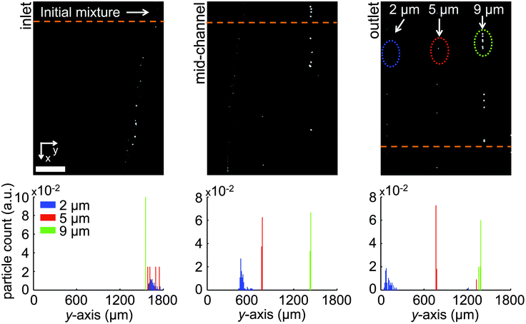 | ||
| Fig. 5 Triple size separation at 8 App and 1200 Hz. The microfluidic channel used in triple separation features electrodes with gaps that gradually increase (from 100 to 300 μm) to trap and focus subsequently smaller microspheres. The microsphere mixture is hydrodynamically focused over the smallest (i.e., 100 μm wide) electrode gap at the inlet of the separation channel. (Top) Fluorescence microscopy snapshots of the separation channel's inlet, center and outlet from above. The largest (9.9 μm) microspheres get trapped and focused over the narrowest electrode gap, as the smaller particles (4.8 μm and 2.2 μm microspheres) are directed to the neighboring spacings. Eventually, all three sizes get trapped and focused along neighboring spacings. (Bottom) PDF's of particle counts along the channel width, as sampled at the corresponding dashed green lines. Scale bar: 400 μm. | ||
One point worth mentioning is that the 2.2 μm diameter microspheres appear less focused within their own output stream compared to the other size groups. One reason for this phenomenon is that the electrode gap that traps the 2.2 μm microspheres is large, resulting in reduced magnetic forces locally and an increase in the time that is necessary for tight focusing. Longer devices could solve this issue if tighter focusing is absolutely necessary, without sacrificing throughput.
Discussion
These initial results demonstrate a throughput of approximately 3 × 10⁴ particles/s per mm2 of channel cross-section. Given the small size of the separation channels used in this study, this performance is somewhat lower than what is achieved with commercial cytometers. However, with a demonstrated throughput of several microlitres/min, this initial prototype device could already be potentially relevant in population characterizations of small samples. For instance, enumeration of CD4 + T lymphocytes from blood for AIDS prognosis, red blood cell count in the context of determining anemia or blood doping in sports, as well as platelet counting for diagnosing clotting disorders can all be accomplished using size-based sorting with about 1 microlitre of blood. The blood sample can be diluted with an appropriate amount of ferrofluid (for instance, 9 microlitres to result in a 1:10 dilution), and the resulting test can be run in our prototype device in less than 10 min. This timescale would make the device clinically relevant for such blood enumeration applications without any further optimization.
However, simply increasing the particle concentration within the channel or using multiple channels in parallel can substantially increase the throughput of ferrofluid-mediated particle sorting. For instance, channel depth can be increased 5-fold (to 100 μm) without a significant loss in particle manipulation capability; this is because currents through the excitation electrodes still mimic the effects of an infinite current sheet for heights much smaller than the traveling field wavelength (∼1200 μm). A deeper channel would necessitate a slight increase in the overall channel length, as it would take several seconds longer for the microparticles to travel up to the channel ceiling in the worst-case scenario. The increase in channel depth could also alleviate shear limitations on angular momentum transfer from nanoparticles to microspheres, allowing for faster input flows. Combined with 25 separation chambers running in parallel (covering up to 4.5 cm in total channel width), the next generation device then should be able to achieve a throughput of 105 particles/s without any further modification to this separation technology.
The maximum throughput potential for future devices would then be limited in part by the dwell time (30 s), the minimum transverse separation distance (∼500 μm), and the minimum particle manipulation velocity (20 μm s−1). We can overcome these three limitations in part by increasing the transverse particle velocity through the use of higher excitation currents and a higher susceptibility ferrofluid. Another consideration regarding upper limits on throughput with such devices involves the availability of ceiling real-estate that can accommodate the increased number of input micro-moieties. A 5-fold increase in channel depth would ultimately result in a corresponding increase in surface concentration of microparticles. Based on our observations of ceiling coverage (supplementary videos†) over the electrode gap where microparticles are focused, we conclude that there exists plenty of ceiling real-estate available to accommodate this increase in surface concentration of microparticles.
The ferrofluid-mediated nanocytometer offers the potential for high sample purities and separation efficiencies that are comparable to those obtained with commercially available devices, but without the use of labels. Alternatively, the microspheres themselves may be used as labels to separate, isolate and concentrate protein, DNA, virus, bacterial or cellular targets from complex mixtures. Specifically, microspheres with different sizes may be simultaneously utilized to isolate multiple different targets from the same sample. Another advantage of our approach is that the microparticles that are separated can be focused into single-file streams within discrete particle tracks, which makes our devices compatible with integrated particle counting and analysis schemes. The disposable nature of the devices prevents cross-contamination between measurements and keeps the costs down. The nanocytometer is easy-to-use and virtually labor-free. With a bio-compatible ferrofluid, the platform is applicable for live cell separation, sorting and population characterization, as well. Integrated with sensors, the nanocytometer could offer rapid and practical new assays in the context of pathogen detection, blood counting and circulating tumor cell isolation, replacing expensive conventional techniques.
Acknowledgements
This work was supported in part by grants from the National Science Foundation, the National Institutes of Health, and the Yale University.Notes and references
- H. J. Gross, et al., Model study detecting breast cancer cells in peripheral blood mononuclear cells at frequencies as low as 10(-7), Proc. Natl. Acad. Sci. U. S. A., 1995, 92(2), 537–41 CrossRef CAS.
- E. Racila, et al., Detection and characterization of carcinoma cells in the blood, Proc. Natl. Acad. Sci. U. S. A., 1998, 95(8), 4589–4594 CrossRef CAS.
- F. Beaujean, Methods of CD34+ cell separation: Comparative analysis, Transfus. Sci., 1997, 18(2), 251–261 Search PubMed.
- A. Bhattacharya, et al., Single centre experience of umbilical cord stem cell transplantation for primary immunodeficiency, Bone Marrow Transplant., 2005, 36(4), 295–299 Search PubMed.
- A. Oshiba, et al., Isolation and Characterization of Human Antigen-Specific B Lymphocytes, Clin. Immunol. Immunopathol., 1994, 72(3), 342–349 Search PubMed.
- C. Peters and C. G. Steward, Hematopoietic cell transplantation for inherited metabolic diseases: an overview of outcomes and practice guidelines, Bone Marrow Transplant., 2003, 31(4), 229–239 Search PubMed.
- A. P. Kodituwakku, et al., Isolation of antigen-specific B cells, Immunol. Cell Biol., 2003, 81(3), 163–170 CrossRef CAS.
- D. P. Collins, B. J. Luebering and D. M. Shaut, T-lymphocyte functionality assessed by analysis of cytokine receptor expression, intracellular cytokine expression, and femtomolar detection of cytokine secretion by quantitative flow cytometry, Cytometry, 1998, 33(2), 249–255 Search PubMed.
- J. A. Shizuru, R. S. Negrin and I. L. Weissman, Hematopoietic Stem and Progenitor Cells: Clinical and Preclinical Regeneration of the Hematolymphoid System, Annu. Rev. Med., 2005, 56(1), 509–538 CrossRef CAS.
- J. Chan, et al., Mechanisms and applications of stem cell gene therapy in autoimmunity, Drug Discovery Today Dis. Mech., 2006, 3(2), 219–223 Search PubMed.
- M. Dainiak, et al.., Methods in Cell Separations, in: Cell Separation, ed. A. Kumar, I. Galaev, and B. Mattiasson, Springer, Berlin/Heidelberg, 2007, pp. 1–18 Search PubMed.
- H. M. Shapiro, Practical Flow Cytometry, John Wiley & Sons, Inc., New Jersey, 2003, pp. 736 Search PubMed.
- X.-B. Wang, et al., Cell Separation by Dielectrophoretic Field-flow-fractionation, Anal. Chem., 2000, 72(4), 832–839 CrossRef.
- J. J. Chalmers, et al., Flow Through, Immunomagnetic Cell Separation, Biotechnol. Prog., 1998, 14(1), 141–148 CrossRef CAS.
- L. Sun, et al., Continuous, flow-through immunomagnetic cell sorting in a quadrupole field, Cytometry, 1998, 33(4), 469–475 CrossRef.
- K. Sung Kim and J.-K. Park, Magnetic force-based multiplexed immunoassay using superparamagnetic nanoparticles in microfluidic channel, Lab Chip, 2005, 5(6), 657–664 RSC.
- J. A. Davis, et al., Deterministic hydrodynamics: Taking blood apart, Proc. Natl. Acad. Sci. U. S. A., 2006, 103(40), 14779–14784 CrossRef CAS.
- L. R. Huang, Continuous Particle Separation Through Deterministic Lateral Displacement, Science, 2004, 304(5673), 987–990 CrossRef CAS.
- Y. Huang, et al., Dielectrophoretic Cell Separation and Gene Expression Profiling on Microelectronic Chip Arrays, Anal. Chem., 2002, 74(14), 3362–3371 CrossRef CAS.
- M. P. Hughes, Strategies for dielectrophoretic separation in laboratory-on-a-chip systems, Electrophoresis, 2002, 23(16), 2569–2582 CrossRef CAS.
- A. R. Kose, et al., Label-free cellular manipulation and sorting via biocompatible ferrofluids, Proc. Natl. Acad. Sci. U. S. A., 2009, 106(51), 21478–21483 CrossRef CAS.
- Y. Gazitt, et al., Purified CD34 + Lin- Thy+ stem cells do not contain clonal myeloma cells, Blood, 1995, 86(1), 381–389 Search PubMed.
- D. Davies, Cell Sorting by Flow Cytometry, in: Flow Cytometry, ed. M. G. Macey, Humana Press, New Jersey, 2007, pp. 257–276 Search PubMed.
- S. Müller and G. Nebe-von-Caron, Functional single-cell analyses: flow cytometry and cell sorting of microbial populations and communities, FEMS Microbiol. Rev., 2010, 34(4), 554–587.
- R. Lacroix, et al., Overcoming limitations of microparticle measurement by flow cytometry, Semin. Thromb. Hemostasis, 2010, 36(8), 807–18 Search PubMed.
- F. W. Kuckuck, B. S. Edwards and L. A. Sklar, High throughput flow cytometry, Cytometry, 2001, 44(1), 83–90 Search PubMed.
- L. W. Diamond, B. N. Nathwani and H. Rappaport, Flow cytometry in the diagnosis and classification of malignant lymphoma and leukemia, Cancer, 1982, 50(6), 1122–1135 Search PubMed.
- B. Barlogie, et al., Flow Cytometry in Clinical Cancer Research, Cancer Research, 1983, 43(9), 3982–3997 Search PubMed.
- Y. Choongho, et al., A three-dimensional dielectrophoretic particle focusing channel for microcytometry applications, J. Microelectromech. Syst., 2005, 14(3), 480–487 CrossRef.
- A. Y. Fu, et al., A microfabricated fluorescence-activated cell sorter, Nat. Biotechnol., 1999, 17(11), 1109–1111 CrossRef CAS.
- D. Huh, et al., Use of Air-Liquid Two-Phase Flow in Hydrophobic Microfluidic Channels for Disposable Flow Cytometers, Biomed. Microdevices, 2002, 4(2), 141–149 CrossRef.
- G.-B. Lee, et al., Hydrodynamic Focusing for a Micromachined Flow Cytometer, J. Fluids Eng., 2001, 123(3), 672–679 CrossRef.
- D. P. Schrum, et al., Microchip Flow Cytometry Using Electrokinetic Focusing, Anal. Chem., 1999, 71(19), 4173–4177 CrossRef CAS.
- N. Pamme, Continuous flow separations in microfluidic devices, Lab Chip, 2007, 7(12), 1644–1659 RSC.
- T. Zhu, F. Marrero and L. Mao, Continuous separation of non-magnetic particles inside ferrofluids, Microfluid. Nanofluid., 2010, 9(4), 1003–1009 Search PubMed.
- M. J. Madou and R. Cubicciotti, Scaling issues in chemical and biological sensors, Proc. IEEE, 2003, 91(6), 830–838 CrossRef CAS.
- Y. Li, et al., Continuous dielectrophoretic cell separation microfluidic device, Lab Chip, 2007, 7(2), 239–248 RSC.
- M. A. M. Gijs, Magnetic bead handling on-chip: new opportunities for analytical applications, Microfluid. Nanofluid., 2004 Search PubMed.
- N. Pamme and C. Wilhelm, Continuous sorting of magnetic cells via on-chip free-flow magnetophoresis, Lab Chip, 2006, 6(8), 974–980 RSC.
- J. Černák, G. Helgesen and A. Skjeltorp, Aggregation dynamics of nonmagnetic particles in a ferrofluid, Phys. Rev. E: Stat., Nonlinear, Soft Matter Phys., 2004, 70(3) Search PubMed.
- B. E. Kashevsky, Nonmagnetic particles in magnetic fluid: Reversal dynamics under rotating field, Phys. Fluids, 1997, 9(6), 1811–1818 Search PubMed.
- M. D. Abramoff, P. J. Magelhaes and S. J. Ram, Image Processing with ImageJ, Biophoton. Int., 2004, 11(7), 6 Search PubMed.
Footnote |
| † Electronic supplementary information (ESI) available: Two supplementary videos that display the binary and ternary separation of different sizes of microspheres within the nanocytometer. See DOI: 10.1039/c1lc20864k |
| This journal is © The Royal Society of Chemistry 2012 |