Microwave-assisted synthesis of ZnO–Y3Al5O12:Ce3+ composites with enhanced visible light photocatalysis
Xinjuan
Liu
a,
Xiaojun
Wang
a,
Huili
Li
a,
Likun
Pan
*a,
Tian
Lv
a,
Zhuo
Sun
a and
Changqing
Sun
b
aEngineering Research Center for Nanophotonics & Advanced Instruments, Ministry of Education, Department of Physics, East China Normal University, Shanghai, China. E-mail: lkpan@phy.ecnu.edu.cn; Fax: +86 21 62234321; Tel: +86 21 62234132
bSchool of Electrical and Electronic Engineering, Nanyang Technological University, Singapore 639798, Singapore
First published on 25th June 2012
Abstract
ZnO–Y3Al5O12:Ce3+ composites were successfully synthesized via a microwave-assisted reaction of the ZnO precursor with a Y3Al5O12:Ce3+ suspension using a microwave synthesis system. The morphology, structure and photocatalytic performance in the degradation of methylene blue (MB) were characterized by scanning electron microscopy, transmission electron microscopy, X-ray diffraction spectroscopy, fluorescence spectrophotometer, and UV-vis absorption spectrophotometer. The results show that the introduction of Y3Al5O12:Ce3+ can enhance the photocatalytic performance of ZnO with a maximum MB degradation rate of 93% under visible light irradiation compared with pure ZnO (13%) mainly due to the light down-converting effect of Y3Al5O12:Ce3+, which facilitates the self-sensitized destruction of MB.
1. Introduction
Semiconductor photocatalysts have attracted considerable attention due to their wide applications such as in the degradation of organic pollutants, reduction of heavy metals, air purification, and hydrogen production.1–11 ZnO has been proven to be a promising photocatalyst for widespread environmental applications due to its intriguing optical and electrical properties, low cost, and ease of availability.12–15 However, its universal use is restricted to ultraviolet (UV) light due to its intrinsically wide band gap. To improve the sunlight photocatalytic efficiency, many promising studies have been reported to develop hybrid materials based on ZnO that respond to visible light, and improve the photocatalytic performance of ZnO, such as doping with nonmetal elements such as C and N,16,17 and coupling with other narrow band-gap semiconductors including CdS,18 ZnSe,19 Fe2O3,20 Cu2O,21 In2O3,22 BiOI,23 and Bi2O3.24The light-converting materials including up-converting and down-converting materials, which transform lower (higher) energy phonons into high (low) energy visible photons, have attracted tremendous interest in recent years.25,26 Investigations have been carried out to study light-converting material–semiconductor hybrid photocatalysts in order to improve the photocatalytic performance.27–30 Wang et al.31,32 fabricated up-converting material–semiconductor photocatalyst composites, such as Er3+:Y3Al5O12–TiO2 and Er3+:Y3Al5O12–TiO2/ZrO2 composites using sol–gel, ultrasonic dispersion and liquid boiling methods. It was found that the composites had a significantly enhanced photocatalytic activity for visible and solar light photocatalytic degradation of congo red and azo fuchsine as compared with the pure semiconductor photocatalyst. Yoon et al.33,34 prepared a CaAl2O4:Eu2+,Nd3+–TiO2 composite using a sol–gel process and atomic layer deposition method and investigated the photocatalytic activity in the degradation of methylene blue (MB) aqueous solution under visible light irradiation. The composite showed much higher photocatalytic reactivity than the pure TiO2 particles. The possible principle of photocatalytic degradation in the presence of up-converting material–semiconductor hybrid photocatalysts was proposed as follows. The up-converting material doped in the semiconductor absorbs visible light and then emits UV light, which can effectively excite the wide band gap semiconductor to generate electron–hole pairs under visible light irradiation. In the same way as for general photocatalytic degradation, these holes not only directly decompose the organics adsorbed on the surface of the semiconductor, but also oxidize water molecules to form ˙OH radicals with high activity and indirectly degrade the organics in aqueous solution.30,31 Recently, Jiang et al.35 fabricated Ce3+:Y3Al5O12 phosphor–TiO2 compound films using micro-arc oxidation and found that the compound films improved the photocatalytic properties in the degradation of MB under UV light irradiation. The enhanced photocatalytic performance arose from the much larger specific surface area, stronger absorption and higher photo-generated current density with the introduction of Ce3+:Y3Al5O12. Unfortunately, the light down-converting property of Ce3+:Y3Al5O12 phosphor had not been utilized in their work.
In this study, we report a one-step synthesis of ZnO–Y3Al5O12:Ce3+ composites using a microwave-assisted reaction of the ZnO precursor with a Y3Al5O12:Ce3+ suspension using a microwave system. Microwave irradiation heats the reactants to a high temperature in a short time by transferring energy selectively to microwave absorbing polar solvents. Thus it can facilitate mass production in a short time span with little energy consumption36,37 and form an intimate contact between the components,38–40 which is crucial for the formation of an electronic interaction and interelectron transfer at the interface. Such a microwave-assisted reaction has hardly been employed to synthesize ZnO–Y3Al5O12:Ce3+ composites although it has been used successfully to fabricate ZnO.41 The photocatalytic performance of the as-synthesized ZnO–Y3Al5O12:Ce3+ composites in the degradation of MB under visible light irradiation was found to be much improved compared with pure ZnO mainly due to the light-converting effect of Y3Al5O12:Ce3+, which facilitates the self-sensitized destruction of MB. To the best of our knowledge, using the light down-converting property of a phosphor in visible light photocatalysis has not yet been reported.
2. Experimental section
2.1 Synthesis of Y3Al5O12:Ce3+ phosphors
Y3Al5O12:Ce3+ phosphors were fabricated by the co-precipitation method reported in our previous work.25,42 In brief, stoichiometric amounts of Y(NO3)2·6H2O, Al(NO3)3·9H2O and Ce(NO3)3·6H2O were dissolved in deionized water to form a transparent stock solution of mother salts. The mixed salt solution was added into a 2 M ammonium bicarbonate solution at a rate of 3 ml min−1 under mild agitation at room temperature. During the co-precipitation, a pH value of 8 was maintained. The slurry obtained was aged for 12 h with agitation by a magnetic agitator. Subsequently, the precipitate was isolated by filtration, washed repeatedly with deionized water and alcohol to completely remove the byproducts of the reaction, and dried at 80 °C for 12 h. Finally, the precursor powder was placed in an alumina crucible and calcined at 1000 °C for 4 h in an alumina tubular furnace in air.2.2 Synthesis of ZnO–Y3Al5O12:Ce3+ composite
A certain amount of the Y3Al5O12:Ce3+ phosphors were added into 20 ml 0.1 M ZnSO4 solution, which was placed in a 35 ml microwave tube, and then the solution was sonicated for 30 min to produce a uniform dispersion. A dilute NaOH solution was dropped in the solution to form a brownish-black suspension with a pH value of 9. The mixture was then put into an automated focused microwave oven (Explorer-48, CEM Co.) and treated at 150 °C with a microwave irradiation power of 150 W for 10 min. The as-synthesized ZnO–Y3Al5O12:Ce3+ samples with 0.5, 1, 3 or 5 wt% Y3Al5O12:Ce3+, named as ZY-0.5, ZY-1, ZY-3 and ZY-5, were isolated by filtration, washed three times with distilled water, and finally dried in a vacuum oven at 60 °C for 24 h. Pure ZnO was also synthesized by a direct microwave assisted reaction for comparison. For the electrochemical impedance spectra (EIS) testing, the as-synthesized composites with 5 wt% cellulose binder were homogeneously mixed in terpineol to form a slurry. Then, the resultant slurries were coated on the FTO using a screen-printing approach. Finally, these prepared electrodes were sintered at 500 °C for 30 min.2.3 Characterization
The surface morphology, structure and composition of the samples were characterized by field-emission scanning electron microscopy (FESEM, Hitachi S-4800), high-resolution transmission electron microscopy (HRTEM, JEOL-2010), X-ray diffraction spectroscopy (XRD, Holland Panalytical PRO PW3040/60) with Cu Kα radiation (V = 30 kV, I = 25 mA), and energy dispersive X-ray spectroscopy (EDS, JEM-2100), respectively. The UV-vis absorption spectra were recorded using a Hitachi U-3900 UV-vis spectrophotometer. Photoluminescence (PL) spectra at room temperature were examined by fluorescence spectrophotometer (HORIBA Jobin Yvon fluoromax-4). The Brunauer–Emmett–Teller (BET) specific surface areas of the samples were evaluated on the basis of nitrogen adsorption isotherms measured at 77 K using a BELSORP-max nitrogen adsorption apparatus (Japan Inc.). All the samples were degassed at 150 °C before nitrogen adsorption measurements. The BET surface area was determined using the adsorption data in the relative pressure (P/P0) range of 0.05–0.35. EIS measurement was carried out on an electrochemical workstation (AUTOLAB PGSTAT302N) under dark conditions using a three electrode configuration with the as-prepared films as working electrodes, a Pt foil as counter electrode and a standard calomel electrode as reference electrode. The electrolyte was 5 mg l−1 MB aqueous solution. EIS were recorded in the frequency range of 0.1 Hz–1 MHz, and the applied bias voltage and ac amplitude were set at open-circuit voltage and 10 mV AC between the counter electrode and the working electrode, respectively.2.4 Photocatalytic experiments
The photocatalytic performance of the as-prepared samples was evaluated through the photocatalytic degradation of MB under visible light irradiation. The samples (2 g l−1) were dispersed in 80 ml MB aqueous solutions (5 mg l−1) and Cr(VI) aqueous solutions (5 mg l−1), respectively. The mixed suspensions were first magnetically stirred in the dark for 30 min to reach the adsorption–desorption equilibrium. Under ambient conditions and stirring, the mixed suspensions were exposed to visible light irradiation produced by a 400 W metal halogen lamp (wavelength: 390–800 nm). At certain time intervals, 2 ml of the mixed suspensions were extracted and centrifuged to remove the photocatalyst. The filtrates were analyzed by recording UV-vis spectra of MB and Cr(VI) using a Hitachi U-3900 UV-vis spectrophotometer.3. Results and discussion
Fig. 1(a) and (b) show the FESEM images of the as-synthesized ZnO and Y3Al5O12:Ce3+. ZnO displays the sheet nanostructure and the Y3Al5O12:Ce3+ particles are monodisperse with diameters in the range of 200–300 nm. Fig. 1(c) displays the FESEM image of ZY-3. The morphologies of ZY-0.5, ZY-1 and ZY-5 (not shown here) are similar to that of ZY-3. It is clearly observed that the introduction of Y3Al5O12:Ce3+ in ZnO does not change the morphology of ZnO. The composition of ZY-3 was identified by EDS linked to FESEM, as shown in Fig. 1(d). The peaks of Zn, O, Y, Al and Ce in the EDS spectrum confirm the existence of ZnO and Y3Al5O12:Ce3+ in the composite. Fig. 2 shows the Ce elemental mapping image by EDS measurement. The distribution of the Ce element indicates that the Ce3+ is highly dispersed in the composite. | ||
| Fig. 1 FESEM images of (a) ZnO nanosheets, (b) Y3Al5O12:Ce3+ particles and (c) ZY-3; (d) EDS spectrum of ZY-3. | ||
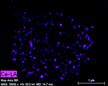 | ||
| Fig. 2 Ce elemental mapping image by EDS measurement. | ||
Fig. 3(a) and (b) show the low-magnification and high-magnification HRTEM images of ZY-3. It confirms the presence of Y3Al5O12:Ce3+ particles contacting with ZnO sheets. The lattice fringes with an interplanar distance of 0.32 nm can be assigned to the (321) plane of cubic Y3Al5O12:Ce3+ (JPCDS 33-0040). The crystallites connecting to the Y3Al5O12:Ce3+ have lattice fringes of 0.28 nm which is ascribed to the (100) plane of ZnO (JCPDS 36-1451).
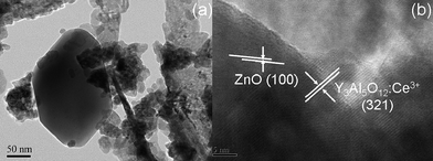 | ||
| Fig. 3 (a) Low-magnification and (b) high-magnification HRTEM images of ZY-3. | ||
The XRD patterns of Y3Al5O12:Ce3+, ZnO and ZY-3 are shown in Fig. 4(a)–(c), respectively. The diffraction pattern of the Y3Al5O12:Ce3+ particles shows that all the peaks can be indexed to the Y3Al5O12 phase (JPCDS 33-0040) and no other crystalline phase such as Y4Al12O9 and YAlO3 can be detected. The peaks in the ZnO pattern at 31.5°, 34.1°, 36°, 47.2°, 56.4°, 62.6°, and 67.7° are indexed to (100), (002), (101), (102), (110), (103), and (112) planes of ZnO (JPCDS 36-1451), respectively. The XRD analysis further shows that the main diffraction peaks of ZY-3 are similar to those of pure ZnO, which demonstrates that the presence of Y3Al5O12:Ce3+ does not result in the development of new crystal orientations or changes in the preferential orientation of ZnO. Compared with pure ZnO, the peaks corresponding to the cubic phase of Y3Al5O12:Ce3+ appear in the XRD pattern of ZY-3, which further confirms the existence of Y3Al5O12:Ce3+ in the composite.
 | ||
| Fig. 4 XRD patterns of (a) Y3Al5O12:Ce3+, (b) ZnO and (c) ZY-3. | ||
The UV-vis absorption spectra of ZnO, ZY-0.5, ZY-1, ZY-3 and ZY-5 are shown in Fig. 5. The sharp characteristic absorption peak at 360 nm is dominated by ZnO. Compared with pure ZnO, the ZnO–Y3Al5O12:Ce3+ composites exhibit higher absorbance in the visible light region and the intensity increases with the increase of Y3Al5O12:Ce3+ content, which is ascribed to the contribution from Y3Al5O12:Ce3+. It is well known that Y3Al5O12:Ce3+ is an important luminescent material and Ce3+ activated Y3Al5O12 exhibits strong absorbance of blue light. The result is similar to those reported in the case of other composite materials.35,43 Such an enhancement of light absorption intensity and range can increase the number of photo-generated electrons and holes to participate in the photocatalytic reaction and enhance the photocatalytic performance.
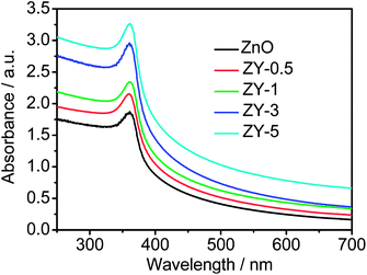 | ||
| Fig. 5 UV-vis absorption spectra of ZnO, ZY-0.5, ZY-1, ZY-3 and ZY-5. | ||
Fig. 6(a) shows the PL excitation and emission spectra of Y3Al5O12:Ce3+. Two absorption peaks at 340 nm and 455 nm are assigned to the characteristic 4f1 → 5d1 transition of Ce3+ ions. A broad emission spectrum with a peak at 525 nm is observed under excitation at 455 nm, which is a typical 5d1 → 4f1 broad emission of Ce3+. The luminescence at 525 nm falls in the absorption range of the dye MB (<663 nm). Therefore, the result indicates that Y3Al5O12:Ce3+ can be used as an effective light down-converting material to improve the light harvesting of the dye MB. Fig. 6(b) shows the PL emission spectra of ZnO and ZY-3 under excitation at 455 nm. Compared with pure ZnO, the much stronger peak at 525 nm appears in the PL spectrum of ZY-3, which further confirms the existence of Y3Al5O12:Ce3+ in the composite.
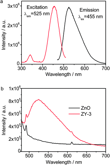 | ||
| Fig. 6 (a) PL excitation and emission spectra of Y3Al5O12:Ce3+ and (b) PL emission spectra of ZnO and ZY-3. | ||
The charge transfer and recombination behavior of the as-prepared samples are studied by analyzing the EIS spectra at open-circuit voltage in the dark. Fig. 7 shows the typical Nyquist plots of ZnO, ZY-0.5, ZY-1, ZY-3 and ZY-5. The semicircle in the EIS spectra is due to the contribution from the charge-transfer impedance (Rct) and constant phase element (CPE) at the photocatalyst/electrolyte interface. The inclined line, resulting from the Warburg impedance ZW, corresponds to the ion-diffusion process in the electrolyte. The corresponding equivalent circuit is shown in the inset of Fig. 7. It can be observed that the Rct decreases with the increase of Y3Al5O12:Ce3+ content. It indicates that the introduction of Y3Al5O12:Ce3+ in ZnO favors the electron transfer and suppresses charge recombination in ZnO,25 which can enhance the photocatalytic performance. However, when the Y3Al5O12:Ce3+ content is further increased above its optimum value, the Rct increases, which is possibly because that excessive Y3Al5O12:Ce3+ can act as a recombination center instead of providing an electron pathway and promote the recombination of electron–hole pairs in Y3Al5O12:Ce3+.
 | ||
| Fig. 7 Nyquist plots of the ZnO, ZY-0.5, ZY-1, ZY-3 and ZY-5. Inset is the corresponding equivalent circuit model. | ||
Photocatalytic degradation of MB by Y3Al5O12:Ce3+, ZnO, ZY-0.5, ZY-1, ZY-3 and ZY-5 was performed under visible light irradiation, as shown in Fig. 8. It is observed that the concentration of MB is hardly reduced under visible light irradiation in the absence of the photocatalyst. The degradation rates of MB for pure ZnO and Y3Al5O12:Ce3+ are 13% and 9%, respectively. When Y3Al5O12:Ce3+ is introduced into ZnO, the degradation rate is increased to 33% and 92% for ZY-0.5 and ZY-1 and reaches a maximum value of 93% for ZY-3 at 240 min. The BET measurement result shows that the specific surface areas of ZnO and ZY-3 are 8.101 and 10.36 m2 g−1, respectively, which indicates that the incorporation of Y3Al5O12:Ce3+ increases the specific surface area of the composite and can enhance the adsorption of MB. The increase of MB adsorption and visible light absorption as well as the reduction of electron–hole pair recombination in ZnO should be responsible for the enhancement of the photocatalytic performance. However, the self-sensitized degradation of the dye should play a critical role in the improvement of photocatalytic performance of ZnO under visible light irradiation.44 MB is excited under visible light irradiation to MB*, followed by photo-induced electron transfer from MB* to ZnO, which reacts with adsorbed oxidants, usually O2, to produce reactive oxygen radicals (O2−).44,45 When Y3Al5O12:Ce3+ phosphors are introduced into ZnO, they can absorb the higher energy photon (455 nm) and re-emit visible light at a longer wavelength (525 nm), which has been confirmed from the PL spectra. These low energy photons can be easily absorbed by MB and thus effectively excite the MB to generate more electron–hole pairs, leading to the obvious improvement of the photocatalytic performance. However, when the Y3Al5O12:Ce3+ content is further increased above its optimum value, the photocatalytic rate decreases. This is possibly because (i) excessive Y3Al5O12:Ce3+ can cover the active sites on the surface of ZnO to decrease the amount of absorbed MB on the surface of ZnO;46 (ii) the Y3Al5O12:Ce3+ simply filters light and decreases the number of charge carriers in the composite to be photo-generated; (iii) more Y3Al5O12:Ce3+ can act as a kind of recombination center instead of providing an electron pathway and promote the recombination of electron–hole pairs in Y3Al5O12:Ce3+, which has been confirmed from the EIS spectra.
 | ||
| Fig. 8 Photocatalytic degradation of MB by Y3Al5O12:Ce3+, ZnO, ZY-0.5, ZY-1, ZY-3 and ZY-5 under visible light irradiation. The concentrations of MB and the photocatalyst are 5 mg l−1 and 2 g l−1, respectively. | ||
It should be noticed from Fig. 6 that Y3Al5O12:Ce3+ exhibits a strong emission at 525 nm with a tail at ∼665 nm and the tiny emission of Y3Al5O12:Ce3+ at ∼665 nm should not be sufficient for the MB's absorption for self-degradation. As a result, the photocatalytic degradation of MB by ZY-3 was performed under irradiation of 665 nm wavelength light produced by a 400 W metal halogen lamp with cut off filter, as shown in Fig. 9 (inset is the transmission spectrum of the 665 nm filter). It can be observed that the degradation rate of MB by ZY-3 at 240 min is only 7%, which indicates this wavelength light is not effective for the self-degradation of MB in the presence of ZnO and Y3Al5O12:Ce3+. Therefore, the Y3Al5O12:Ce3+ in the composite should be playing an important role.
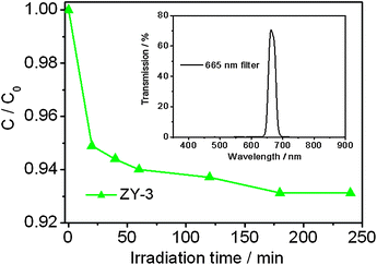 | ||
| Fig. 9 Photocatalytic degradation of MB by ZY-3 under 665 nm wavelength light irradiation. The concentrations of MB and the photocatalyst are 5 mg l−1 and 2 g l−1, respectively. The inset is the transmission spectrum of the 665 nm filter. | ||
Another experiment to investigate the photocatalytic reduction of Cr(VI) by Y3Al5O12:Ce3+, ZnO and ZY-3 was also carried out under visible light irradiation for comparison, as shown in Fig. 10, because Cr(VI) has no self-sensitized destruction path. It is observed that the removal rates of Cr(VI) for pure ZnO and Y3Al5O12:Ce3+ are 12% and 12%, respectively, while the reduction rate of Cr(VI) only reaches a value of 45% for ZY-3 at 240 min. The enhancement of the photocatalytic performance should be ascribed to the increase of Cr(VI) adsorption and visible light absorption as well as the reduction of electron–hole pair recombination in ZnO with the incorporation of Y3Al5O12:Ce3+. The large difference in the photocatalytic performance of ZY-3 in the degradation of MB and the reduction of Cr(VI) indicates the contribution of the light down-converting effect of Y3Al5O12:Ce3+ to the photocatalytic performance by enhancing the self-sensitized degradation of MB.
 | ||
| Fig. 10 Photocatalytic reduction of Cr(VI) by Y3Al5O12:Ce3+, ZnO and ZY-3 under visible light irradiation. The concentrations of Cr(VI) and the photocatalyst are 5 mg l−1 and 2 g l−1, respectively. | ||
4. Conclusions
ZnO–Y3Al5O12:Ce3+ composites were successfully synthesized via a microwave-assisted reaction of the ZnO precursor with a Y3Al5O12:Ce3+ suspension using a microwave system and their photocatalytic performances were investigated. The results indicate that (i) ZnO–Y3Al5O12:Ce3+ composites exhibit a better photocatalytic performance than pure ZnO; (ii) the photocatalytic performance of ZnO–Y3Al5O12:Ce3+ is dependent on the proportion of Y3Al5O12:Ce3+ in the composites and the ZnO–Y3Al5O12:Ce3+ composite with 3 wt% Y3Al5O12:Ce3+ achieves the highest MB degradation rate of 93%; (iii) the enhanced photocatalytic performance is ascribed to the increase of MB adsorption and visible light absorption, the reduction of photoelectron–hole pair recombination in ZnO with the introduction of Y3Al5O12:Ce3+ and the light down-converting effect of Y3Al5O12:Ce3+, which facilitates the self-sensitized degradation of MB. Semiconductor photocatalysts doped with down-converting luminescent materials should be promising visible light photocatalysts for treating dye wastewater.Acknowledgements
Financial support from Special Project for Nanotechnology of Shanghai (no.11nm0501200) and ECNU Reward for Excellent Doctors in Academics (no. XRZZ2011017) are gratefully acknowledged.References
- J. Du, L. R. Espelt, I. A. Guzei and T. P. Yoon, Chem. Sci., 2011, 2, 2115 RSC.
- Q. J. Xiang, J. G. Yu and M. Jaroniec, Chem. Soc. Rev., 2012, 41, 782 RSC.
- K. F. Zhou, Y. H. Zhu, X. L. Yang, X. Jiang and C. Z. Li, New J. Chem., 2011, 35, 353 RSC.
- J. T. Zhang, Z. G. Xiong and X. S. Zhao, J. Mater. Chem., 2011, 21, 3634 RSC.
- Q. Shen, W. Zhang, Z. P. Hao and L. D. Zou, Chem. Eng. J., 2010, 165, 301 CrossRef CAS.
- F. Y. Shen, W. X. Que, Y. L. Liao and X. T. Yin, Ind. Eng. Chem. Res., 2011, 50, 9131 CrossRef CAS.
- M. Y. Xing, Y. M. Wu, J. L. Zhang and F. Chen, Nanoscale, 2010, 2, 1233 RSC.
- V. Iliev, D. Tomova and S. Rakovsky, Desalination, 2010, 260, 101 CrossRef CAS.
- X. H. Peng, A. C. Santulli, E. Sutter and S. S. Wong, Chem. Sci., 2012, 3, 1262 RSC.
- Z. Ren, E. Kim, S. W. Pattinson, K. S. Subrahmanyam, C. N. R. Rao, A. K. Cheetham and D. Eder, Chem. Sci., 2012, 3, 209 RSC.
- N. Wang, T. Tachikawa and T. Majima, Chem. Sci., 2011, 2, 891 RSC.
- L. W. Zhang, H. Y. Cheng, R. L. Zong and Y. F. Zhu, J. Phys. Chem. C, 2009, 113, 2368 Search PubMed.
- J. T. Tian, L. J. Chen, Y. S. Yin, X. Wang, J. H. Dai, Z. B. Zhu, X. Y. Liu and P. W. Wu, Surf. Coat. Technol., 2009, 204, 205 CrossRef CAS.
- H. B. Fu, T. G. Xu, S. B. Zhu and Y. F. Zhu, Environ. Sci. Technol., 2008, 42, 8064 CrossRef CAS.
- X. J. Liu, L. K. Pan, Q. F. Zhao, T. Lv, G. Zhu, T. Q. Chen, T. Lu, Z. Sun and C. Q. Sun, Chem. Eng. J., 2012, 183, 238 CrossRef CAS.
- S. Cho, J. W. Jang, J. S. Lee and K. H. Lee, CrystEngComm, 2010, 12, 3929 RSC.
- S. F. Chen, W. Zhao, S. J. Zhang and W. Liu, Chem. Eng. J., 2009, 148, 263 CrossRef.
- P. Kundu, P. A. Deshpande, G. Madras and N. Ravishankar, J. Mater. Chem., 2011, 21, 4209 RSC.
- S. Cho, J. W. Jang, J. Kim, J. S. Lee, P. W. Choi and K. H. Lee, Langmuir, 2011, 27, 10243 CrossRef CAS.
- Y. Liu, L. Yu, Y. Hu, C. F. Guo, F. M. Zhang and X. W. Lou, Nanoscale, 2012, 4, 183 RSC.
- C. Xu, L. X. Cao, G. Su, W. Liu, H. Liu, Y. Q. Yu and X. F. Qu, J. Hazard. Mater., 2010, 176, 807 CrossRef CAS.
- Z. Y. Wang, B. B. Huang, Y. Dai, X. Y. Qin, X. Y. Zhang, P. Wang, H. X. Liu and J. X. Yu, J. Phys. Chem. C, 2009, 113, 4612 CAS.
- J. Jiang, X. Zhang, P. B. Sun and L. Z. Zhang, J. Phys. Chem. C, 2011, 115, 20555 CAS.
- C. Z. Li, J. Y. Zhang, J. A. Yang, T. M. Wang, X. Lv and Z. L. Tang, Appl. Catal., A, 2011, 402, 80 CrossRef CAS.
- G. Zhu, X. J. Wang, H. L. Li, L. K. Pan, H. C. Sun, X. J. Liu, T. Lv and Z. Sun, Chem. Commun., 2012, 48, 958 RSC.
- X. J. Wang, M. C. Zhang, H. Ding, H. L. Li and Z. Sun, J. Alloys Compd., 2011, 509, 6317 CrossRef CAS.
- C. H. Li, F. Wang, J. Zhu and J. C. Yu, Appl. Catal., B, 2010, 100, 433 CrossRef CAS.
- D. X. Hou, L. Feng, J. B. Zhang, S. S. Dong, D. D. Zhou and T. T. Lim, J. Hazard. Mater., 2012, 199–200, 301 CrossRef CAS.
- G. J. Feng, S. W. Liu, Z. L. Xiu, Y. Zhang, J. X. Yu, Y. Chen, P. Wang and X. J. Yu, J. Phys. Chem. C, 2008, 112, 13692 CAS.
- Z. J. Zhang, W. Z. Wang, W. Z. Yin, M. Shang, L. Wang and S. M. Sun, Appl. Catal., B, 2010, 101, 68 CrossRef CAS.
- J. Wang, R. H. Li, Z. H. Zhang, W. Sun, R. Xu, Y. P. Xie, Z. Q. Xing and X. D. Zhang, Appl. Catal., A, 2008, 334, 227 CrossRef CAS.
- L. N. Yin, J. Q. Gao, J. Wang, X. Y. Luan, P. L. Kang, Y. Li, K. Li and X. D. Zhang, Res. Chem. Intermed., 2012, 38, 523 CrossRef CAS.
- J. H. Yoon and J. S. Kim, Ionics, 2010, 16, 131 CrossRef CAS.
- J. H. Yoon, S. C. Jung and J. S. Kim, Mater. Chem. Phys., 2011, 125, 342 CrossRef CAS.
- X. D. Jiang, Y. Q. Wang and C. X. Pan, J. Alloys Compd., 2011, 509, L137 CrossRef CAS.
- A. V. Murugan, T. Muraliganth and A. Manthiram, Chem. Mater., 2009, 21, 5004 CrossRef CAS.
- F. Y. Jiang, C. M. Wang, Y. Fu and R. C. Liu, J. Alloys Compd., 2010, 503, L31 CrossRef CAS.
- G. Zhu, L. K. Pan, T. Xu, Q. Zhao, B. Lu and Z. Sun, Nanoscale, 2011, 3, 2188 RSC.
- X. J. Liu, L. K. Pan, T. Lv, T. Lu, G. Zhu, Z. Sun and C. Q. Sun, Catal. Sci. Technol., 2011, 1, 1189 CAS.
- X. J. Liu, L. K. Pan, T. Lv, G. Zhu, Z. Sun and C. Q. Sun, Chem. Commun., 2011, 47, 11984 RSC.
- P. L. Zhu, J. W. Zhang, Z. S. Wu and Z. J. Zhang, Cryst. Growth Des., 2008, 8, 3148 CAS.
- X. J. Wang, M. C. Zhang, H. Ding, H. L. Li and Z. Sun, J. Alloys Compd., 2011, 509, 6317 CrossRef CAS.
- Z. J. Zhang, W. Z. Wang, J. Xu, M. Shang, J. Ren and S. M. Sun, Catal. Commun., 2011, 13, 31 CrossRef CAS.
- T. Lv, L. K. Pan, X. J. Liu, T. Lu, G. Zhu, Z. Sun and C. Q. Sun, Catal. Sci. Technol., 2012, 2, 754 CAS.
- Z. G. Xiong, L. L. Zhang, J. Z. Ma and X. S. Zhao, Chem. Commun., 2010, 46, 6099 RSC.
- J. Q. Gao, X. Y. Luan, J. Wang, B. X. Wang, K. Li, Y. Li, P. L. Kang and G. X. Han, Desalination, 2011, 268, 68 CrossRef CAS.
| This journal is © The Royal Society of Chemistry 2012 |
