Electrospinning of in situ crosslinked collagen nanofibers
Linghui
Meng
a,
Oliver
Arnoult
b,
Meghan
Smith
c and
Gary E.
Wnek
*a
aDepartment of Macromolecular Science and Engineering, Case Western Reserve University, 2100 Adelbert Road, Cleveland, OH 44106, USA. E-mail: gew5@case.edu; Fax: +1 216 368-4202; Tel: +1 216 368-3116
bSaint-Gobain Performance Plastics, 335 North Diamond Street, Ravenna, OH 44122, USA. E-mail: oarnoult@gmail.com; Tel: +1 330 274-6537
cNuVention Solutions Inc., 7650 Hub Parkway, Valley View, OH 44102, USA. E-mail: mes@nuventionsolutions.com; Fax: +1 216 525-0183; Tel: +1 216 525-0183
First published on 9th July 2012
Abstract
A simple one-step approach to electrospin Type I collagen in the presence of the chemical crosslinking agents 1-ethyl-3-(3-dimethyl-aminopropyl)-1-carbodiimide hydrochloride (EDC) and N-hydroxysuccinimide (NHS) has been developed to generate water-insoluble collagen nanofiber scaffolds without the need for post-crosslinking. SEM images indicate that fibrous surface morphology of collagen scaffolds was well retained after the in situ crosslinking process and following water treatment. The resultant collagen demonstrated a similar uniaxial tensile behavior of native tissue in mechanical testing.
Introduction
Collagen fibers are of particular interest and importance in tissue engineering and regenerative medicine.1,2 Due to high porosity and large surface area, non-woven scaffolds of electrospun collagen nanofibers can serve as an ideal engineering scaffold to mimic the biochemical and ultra-structural properties of the native extracellular matrix (ECM) of tissues.3,4 However, when pure collagen is regenerated by means of electrospinning, no matter what solvent (e.g. acidic water, HFIP, or ethanol–PBS) is used, the resulting fibers inevitably present insufficient resistance in water to withstand dissolution and poor mechanical firmness.5–7 This is due to the lack of native inter- and intra-molecular crosslinks in the reconstituted collagen, which leads to weakly bonded fragments of collagen molecules.8Much of the effort and energy in the past has been focused on crosslinking of collagen, such as exposure to ultraviolet light,9 enzymatic treatment using transglutaminase,10 and the use of chemical crosslinking agents such as glutaraldehyde (GA),11 epoxy compounds,12 and 1-ethyl-3-(3-dimethyl-aminopropyl)-1-carbodiimide hydrochloride (EDC), either alone or with N-hydroxysuccinimide (NHS).7,13 Among them, the chemical crosslinking agent EDC has been widely used to crosslink reconstituted collagen fibrils (i.e. collagen molecules removed from tissues via acid or enzyme extraction that spontaneously form fibrils), insoluble collagen, and collagen fibers from intact tissues.2,3
Typical protocols for crosslinking electrospun collagen with EDC frequently suffer from poor results with respect to the structural aspect of the scaffold.7,13 It has been reported that the collagen scaffold shrinks during crosslinking and the open structure which is desirable for the cell repopulation on the scaffold is almost obstructed by film-like structure on the surface of the electrospun mats,13 hence partially defeating the purpose of electrospinning of collagen. Although electrospun blends of collagen with other natural or synthetic polymers, or fabrication of core–sheath collagen fibers through coaxial electrospinning, have been proven successful in maintaining the fibrous structure and initial cell studies,5,14 it is desirable to be able to work with collagen-only electrospun scaffolds for such applications as cartilage tissue engineering or skin replacement.
Furthermore, conventional methods of creating crosslinked collagen fibers, based on physical or chemical treatments, are always two-step methods: collagen fibrous scaffold preparation followed by post-production crosslinking. Such post-crosslinking procedures frequently increase the complexity of the collagen production and can be technically limited by a high cost–benefit ratio for large-scale implementation.15 Therefore, it is highly desirable to simplify the procedures and resolve the aforementioned negative influences brought by EDC post-crosslinking for applications where collagen fiber scaffolds would be used. Accordingly, the focus of this paper is the development of a novel method to combine fiber formation and post-crosslink treatment in a single step to fabricate water-stable collagen scaffolds and maintain the desirable fibrous morphology.
Results and discussion
EDC–NHS crosslinking
Chemical crosslinking of collagen with EDC and NHS is one of the best methods to produce non-toxic, water-stable collagen products.15,16 NHS is believed to afford a more hydrolysis-resistant intermediate, thus improving crosslinking efficiency. A literature survey regarding collagen crosslinking indicates that a wide range of concentrations of EDC and NHS have been used, but the NHS–EDC ratio typically does not exceed 1![[thin space (1/6-em)]](https://www.rsc.org/images/entities/char_2009.gif) :
:![[thin space (1/6-em)]](https://www.rsc.org/images/entities/char_2009.gif) 1.13–18
1.13–18
Surprisingly, an excess amount of NHS has been found by our laboratory to be able to delay the total coupling reaction in a controlled fashion. A series of rheological analyses has been performed on the collagen-ethanol–PBS solutions, a formulation developed in our laboratory, containing different molar ratios of NHS and EDC at room temperature. The apparent gelation time is defined as the time at which the shear storage (G′) and loss (G′′) moduli are approximately equal as determined rheologically in dynamic oscillatory shear experiments. The relationship between the apparent gelation time and the molar ratio of NHS and EDC is plotted in Fig. 1.
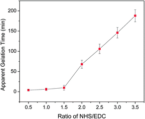 | ||
| Fig. 1 Plot of the apparent gelation time as a function of the molar ratio of NHS and EDC (n = 3). | ||
When the concentration of EDC is fixed at 200 mM, the apparent gelation time is highly dependent on the amount of NHS in solution. Fig. 1 shows that the addition of NHS to the EDC solution has little influence on the apparent gelation time initially. The collagen–ethanol–PBS solution turned to a gel in minutes when the concentration of NHS was relatively low. However, at the point where the ratio increased up to about 1.5, there was a prompt increase in the apparent gelation time, and then it increased almost linearly with the molar ratio of NHS to EDC in the range higher than about 2. Therefore, if the amount of NHS added to collagen solution exceeds twice as much as that of EDC, the apparent gelation time will increase from minutes to hours, which is very valuable for collagen nanofiber scaffold fabrication. During this desirable period, the benign collagen solution can be processed into a variety of shapes and morphologies. Significantly, electrospinning of collagen fibers from the benign solvent system ethanol-PBS became possible, with crosslinking occurring in situ afterward.
In situ crosslinked collagen nanofibers
Accordingly, in situ crosslinking nanofibers were successfully fabricated from a benign collagen solution containing 200 mM EDC and 400 mM NHS through a traditional single jet electrospinning setup. Typical SEM images of the electrospun collagen fibers are given in Fig. 2, which show cylindrical and continuous nanofibers possessing a common feature of random arrays and a very porous structure. The average fiber diameter calculated for in situ crosslinking, electrospun collagen fiber mats is in the range of 0.42 ± 0.11 μm, which is almost twice the size of the collagen fibers generated from ethanol–PBS without crosslinkers.7 This is expected because the addition of crosslinker EDC into the collagen solution inevitably increased the viscosity, even though macroscopic gelation was postponed by the presence of an excess amount of NHS, and a higher viscosity of collagen solution resulted in larger fibers formed. Similar results were also found in rheological experiments. The storage modulus (G′) of in situ crosslinking collagen solution kept increasing until the dynamic oscillatory shear testing finished, which indicated that the viscosity of solution gradually increased after mixing the collagen and the crosslinkers together. Moreover, it is of interest to note that the average diameter of in situ crosslinked collagen fibers slightly increased from 0.35 to 0.46 μm during electrospinning, as shown in Fig. 2(d), which suggests that the onset of crosslinking occurs during that time. | ||
| Fig. 2 Typical SEM images of electrospun in situ crosslinked collagen fiber at low (a) and high (b) magnification. (c) Distribution of fiber diameter. (d) Diameter of in situ crosslinked collagen fibers increased during electrospinning processing. | ||
After electrospinning, the resulting in situ crosslinked collagen nanofiber scaffolds were stored in desiccators which had different humidity levels. The equilibrium relative humidity was controlled by the use of saturated salt solutions. These salt solutions were made up as a slushy mixture with distilled water and chemically pure salts and enclosed in the sealed glass desiccators. For humidity control purposes, saturated solutions of magnesium chloride, potassium carbonate and magnesium nitrate were used to provide the equilibrium relative humidity of 33%, 43% and 53% at room temperature,19 respectively.
SEM images of electrospun, in situ crosslinked collagen fibers stored at different humidity levels for certain periods of time are shown in Fig. 3, and indicate that the relative humidity is apparently an important parameter to control the fiber morphology of in situ crosslinked collagen after electrospinning. Collagen fiber scaffolds stored at 33% humidity for 3 days (Fig. 3a) still possessed individual fiber features, while some “melting” of fibers was observed with samples stored at 53% humidity for only one day (Fig. 3c). High humidity might plasticize the collagen before extensive crosslinking by incorporated EDC and NHS, while low humidity may limit the mobilities of the crosslinkers and collagen chains in the fibers, which resulted in low crosslink efficiency. The collagen fibers were found to be insufficiently crosslinked at 33% humidity after 3 days and partially disintegrated when placed in the water. Therefore, an appropriate humidity is needed to control in situ crosslinking of collagen. In this study, 43% relative humidity provided by saturated potassium carbonate solution was demonstrated to be satisfactory and thus used for the rest of the experiments.
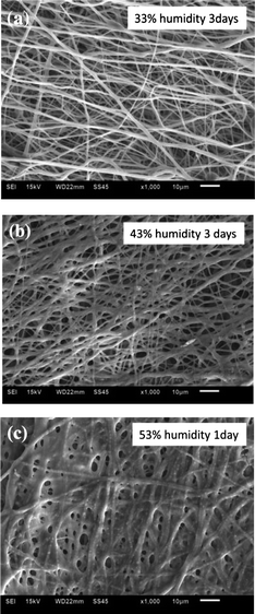 | ||
| Fig. 3 Effect of relative humidity on the morphology of collagen fibers. SEM images of electrospun in situ crosslinking collagen fibers at humidity of 33% for 3 days (a), 43% for 3 days (b) and 53% for 1 day (c). | ||
Stability in water
Post-crosslinking of collagen fiber scaffolds was also performed by immersing the collagen scaffolds electrospun from ethanol–PBS without crosslinkers into 200 mM each of EDC and NHS in ethanol for 4 hours. After the post-crosslinking process, the resulting collagen scaffolds shrank to about 40% of the original dimensions when immersed in the water, as shown in Fig. 4a and b.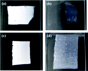 | ||
| Fig. 4 Appearances of electrospun collagen scaffolds post-crosslinked (a and b) and in situ crosslinked (c and d) with EDC–NHS. The scaffolds were placed on the glass slides before (a and c) and after (b and d) water treatment. | ||
In contrast, the in situ crosslinked collagen scaffolds normally swelled up to two-fold of the original size when they were hydrated, as shown in Fig. 4c and d. Furthermore, the water-treated, in situ crosslinked collagen scaffolds still possess a very porous structure, as displayed in Fig. 5, which is one of the most important features of the scaffolds to begin with. Such prominent difference in water stability of collagen scaffolds crosslinked post-electrospinning vs. the in situ method may arise from the distribution of crosslinkers in the collagen fibers. It has been reported that the coupling reaction in the traditional two-step crosslinking approach is mainly concentrated on the outer surface of collagen fibers due to the slow penetration of EDC and NHS into dense fibers, which is increasingly retarded as crosslinking continues at/near the surfaces.20 Conversely, it is believed that EDC and NHS are more uniformly distributed in the collagen fibers by using the in situ method developed in this work and that crosslinking reactions take place throughout the fibers, resulting in more homogeneously crosslinked collagen scaffolds.
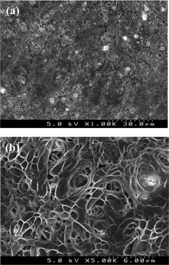 | ||
| Fig. 5 SEM images of electrospun in situ crosslinking collagen scaffolds after water-treatment at low (a) and high (b) magnifications. | ||
The extent of crosslinking can be indicated by the denaturation temperature of collagen, as a higher crosslinking degree is expected to afford a higher denaturation temperature.21 The denaturation temperatures of crosslinked collagen samples were determined by using differential scanning calorimetry (DSC) and the results are plotted in Fig. 6. Post-crosslinked and in situ crosslinked collagen have the denaturation temperature of approximately 65 and 79 °C, respectively, which suggests that the in situ method produced a higher crosslinking degree for the collagen scaffolds.
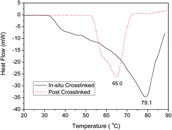 | ||
| Fig. 6 Typical DSC thermogram of in situ and post-crosslinked collagen samples. | ||
Mechanical properties
To evaluate the mechanical properties of the electrospun, in situ crosslinked collagen scaffolds, the uniaxial tensile response of the resultant mats was measured in both dry and hydrated states. The hydrated samples were used to show tensile behavior of electrospun in situ crosslinked collagen fibers under approximate physiological conditions. Uniaxial tensile testing performed on the in situ crosslinked collagen scaffolds indicated a significant difference in tensile behaviors of the dry and hydrated samples. A representative plot of the stress–strain relationship of the dry scaffolds exhibited a shape characteristic similar to that of many synthetic polymers, with a linear elastic region followed by a period of plastic deformation until failure, as shown in Fig. 7. In contrast, the hydrated collagen scaffolds demonstrated a uniaxial J-shaped stress–strain curve, which is roughly similar to that of many native tissues. The typical tensile properties in terms of peak stress and strain at break are summarized in Table 1, in which the hydrated crosslinked collagen scaffolds show a significantly greater strain and a smaller stress than those of the dry samples. This is not surprising, because the electrospun in situ crosslinked collagen scaffolds swelled to approximately twice the original dimensions, as noted earlier. Furthermore, a large amount of water present in the hydrated, crosslinked collagen scaffolds is expected to increase the mobility of the polymer chains. Consequently, a high strain was expected from the hydrated samples.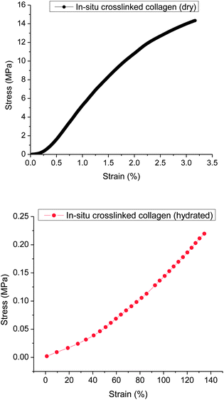 | ||
| Fig. 7 Representative plots of stress–strain curves to demonstrate the difference in behavior of in situ crosslinked collagen dry and hydrated samples. | ||
| Samples | Peak stress (MPa) | Strain at break (%) |
|---|---|---|
| Dry crosslinked collagen | 14.53 ± 1.61 | 3.28 ± 0.12 |
| Hydrated crosslinked collagen | 0.22 ± 0.02 | 134.5 ± 10.0 |
Plausible explanations
The EDC crosslinking reaction begins with the formation of an amide bond by activation of the side chain carboxylic acid groups of aspartic and glutamic acids, followed by aminolysis of the intermediate O-isoacylurea by the primary amino groups of lysine or hydroxylysine residues on the adjacent collagen fibrils, forming intra- and inter-helical crosslinks.13,17 However, the amine-reactive O-acylisourea intermediate is susceptible to hydrolysis, making it unstable and short-lived in aqueous solution. The addition of NHS stabilizes the amine-reactive intermediate by converting it to less-reactive NHS ester, thus increasing the efficiency of coupling with available amine groups.18 Consequently, an excess of NHS present in the reaction mixture may convert most of the active EDC intermediates to the less active NHS esters, which inevitably slows down the coupling to a second collagen molecule. Moreover, the newly formed NHS esters may undergo nucleophilic attack from either a primary amino group of second collagen molecule or the N–OH group of the NHS. The crosslinking rate would then depend on competition between NHS and amino groups of collagen molecules to react with an NHS ester already linked to a collagen molecule. Since excess NHS molecules should be highly mobile and more accessible to the amine-reactive NHS esters, an ‘NHS-ester exchange’ might be important. Therefore, the excess amount of NHS present in the crosslinking mixture retards the rate of amide bond formation, leading to postponement of the crosslinking reaction.Conclusions
In order to address problems plaguing traditional collagen crosslinking methods, such as dimensional shrinking and loss of porous morphology, and to simplify the crosslinking procedure for electrospun collagen scaffolds, a novel single-step, in situ crosslinking approach was developed. The excess amount of NHS present in the crosslinking mixture was found to delay the EDC coupling reaction up to several hours. Two plausible reasons for the delayed crosslinking reaction in the presence of excess NHS are discussed: one proposes a large amount of less active amine-reactive NHS ester formed before the stable amide bond formation; the other concerns a competition between the amino groups of the second collagen molecule and the mobile NHS molecules to attack the aforementioned NHS ester.Water-stable collagen nanofibers with a diameter of 0.42 ± 0.11 μm were successfully generated by electrospinning an in situ crosslinking collagen solution. The diameter of electrospun collagen fibers slightly increased during electrospinning, which indicated the onset of in situ crosslinking. Humidity was found to be an important factor to control the in situ crosslinking rate and the subsequent fiber morphology, and the humidity of 43% was found to be preferable to afford a sufficiently crosslinked collagen network within 3 days.
The in situ crosslinked collagen scaffolds exhibited swelling when placed in water, in contrast to the dimensional shrinking frequently observed in post-crosslinked electrospun collagen mats. The porous surface morphology of the resulting mats was preserved during water treatment, which is one of the most important features of the in situ crosslinked scaffolds. The in situ crosslinked collagen demonstrated a similar uniaxial tensile behavior of native tissue in mechanical testing. This in situ crosslinking technique may also have applicability with other biomaterials including polypeptides, proteins and polysaccharides, to produce versatile structures for tissue engineering.
Experimental part
Materials
Lyophilized collagen (semed S, acid-soluble), principally collagen Type I with ca. 5% Type III, from bovine dermis was kindly gifted by Kensey Nash Corporation. Ethanol, EDC, NHS, magnesium nitrate hexahydrate and potassium carbonate were purchased from Sigma-Aldrich Co. Ltd and used without further purification. Potassium chloride, sodium chloride, monobasic potassium phosphate, dibasic sodium chloride heptahydrate and magnesium chloride hexahydrate were purchased from Fisher Scientific and used without further purification. Phosphate buffered saline (PBS) 20× buffer was prepared according to the literature.7Preparation of in situ crosslinking collagen solution
In situ crosslinking collagen solution was prepared by mixing the crosslinkers and collagen in a very particular order. First EDC and NHS were added to ethanol in pre-calculated quantities and ratios. The ethanol mixture was then magnetically stirred until the EDC and NHS were fully dissolved. Then 20× PBS buffer (pH 7.4) was added to the ethanol mixture in a buffer![[thin space (1/6-em)]](https://www.rsc.org/images/entities/char_2009.gif) :
:![[thin space (1/6-em)]](https://www.rsc.org/images/entities/char_2009.gif) ethanol ratio of 50
ethanol ratio of 50![[thin space (1/6-em)]](https://www.rsc.org/images/entities/char_2009.gif) :
:![[thin space (1/6-em)]](https://www.rsc.org/images/entities/char_2009.gif) 50 by volume. The collagen was then added to ethanol–PBS at a concentration of 16% by weight. It was important to add the collagen quickly after mixing the buffer and ethanol, otherwise phase separation occurred and the salts in buffer precipitated in ethanol. Once all of the collagen had been added, it was magnetically stirred for roughly 5 minutes in order to make a uniform solution which was then placed in a syringe and used either for electrospinning or rheological experiments.
50 by volume. The collagen was then added to ethanol–PBS at a concentration of 16% by weight. It was important to add the collagen quickly after mixing the buffer and ethanol, otherwise phase separation occurred and the salts in buffer precipitated in ethanol. Once all of the collagen had been added, it was magnetically stirred for roughly 5 minutes in order to make a uniform solution which was then placed in a syringe and used either for electrospinning or rheological experiments.
Rheological experiment
Dynamic oscillatory shear experiments were carried out on the in situ crosslinking collagen solutions with different molar ratios of NHS to EDC at room temperature. The concentration of EDC was fixed at 200 mM in ethanol. A 40 mm diameter, 2° steel cone and plate geometry was used with a solvent trap, which helped to prevent the evaporation of the alcohol from the sample. The oscillatory mode had a frequency of 6.283 rad s−1 and a strain of 0.2% and longtime sweep experiments were conducted. The storage (G′) and loss (G′′) modulus as well as the loss tangent, tan σ (= G′′/G′), were recorded as a function of time on a TA Instruments AR-2000ex Rheometer. The apparent gelation time was rheologically determined by the time at which G′ was equal to G′′.Electrospinning of in situ crosslinking collagen
The freshly made in situ crosslinking collagen solution was loaded into a 5 mL BD syringe with a 21 gauge blunt needle, which was then placed in a syringe pump. The process parameters (e.g. flow rate, potential field, and needle-collector distance) and environmental conditions (e.g. humidity and temperature) were varied to optimize the stability of the electrostatic jet. Electrospinning was typically carried out at 20 kV with a pump rate of 0.5 mL h−1 at a relatively low humidity (20%) controlled using Drierite desiccant (anhydrous calcium sulfate). A drum rotating at 5 m s−1 was placed 12 cm from the needle and the electrospun fibers were collected at room temperature. The resulting collagen fiber scaffolds were then stored in desiccators under controlled humidity. Saturated solutions of magnesium chloride, potassium carbonate and magnesium nitrate were used to provide the relative humidity of 33%, 43% and 53% in desiccators, respectively.19Characterization of fiber morphology
In order to monitor the change of fiber morphology during the electrospinning process, small amounts of electrospun collagen fibers were collected on glass slides at various time points and observed using an optical microscope (Nikon Eclipse TS100). Morphological characterization was also performed on a JEOL JSM-6510LV scanning electron microscope (SEM) in secondary electron imaging (SEI) mode. Electrospun collagen mats were sputter-coated with a 5 nm gold layer and observed using a SEM at 5 kV. Data treatment was done with free Image J software. Water-treated, in situ crosslinked electrospun collagen samples were prepared by soaking the pre-made crosslinked collagen scaffolds in PBS for approximately 30 min followed by rinsing with water, and then dried in vacuo for sputter-coating and SEM imaging.Differential scanning calorimetry (DSC)
Thermal phase transitions were obtained using a TA Instruments Q2000 DSC. 1–2 mg of collagen samples immersed in 10 mg of water were loaded into TA Hermetic pans and then gently packed. The reference cell contained a similar quantity of water. Experimental temperatures ranged from approximately 20 °C to 90 °C with a heating rate of 2 °C per min under a N2 atmosphere. The collagen denaturation temperature was determined from the peak minimum (endothem) in the heat flow signal.Characterization of mechanical properties
Mechanical testing of the electrospun collagen scaffolds was performed on a dynamic mechanical analyzer (DMA-Q800, TA Instruments Inc.) in the ramp force mode. Collagen samples were carefully cut into rectangular strips with approximately a 5![[thin space (1/6-em)]](https://www.rsc.org/images/entities/char_2009.gif) :
:![[thin space (1/6-em)]](https://www.rsc.org/images/entities/char_2009.gif) 1 length
1 length![[thin space (1/6-em)]](https://www.rsc.org/images/entities/char_2009.gif) :
:![[thin space (1/6-em)]](https://www.rsc.org/images/entities/char_2009.gif) width ratio. The width and thickness of the fibrous specimen were measured and loaded into the tensile testing fixture, and a ramp force of (0.5 × width × thickness) N min−1 was applied at room temperature to obtain the stress–strain profile. Universal Analysis software (TA Instruments) was used to determine elastic modulus, and stress and strain at break of all samples. Mechanical properties of the crosslinked mats were also measured in the hydrated state prepared by soaking the mats in PBS for approximately 30 minutes at room temperature. Uniaxial tensile testing of these mats was performed as described above.
width ratio. The width and thickness of the fibrous specimen were measured and loaded into the tensile testing fixture, and a ramp force of (0.5 × width × thickness) N min−1 was applied at room temperature to obtain the stress–strain profile. Universal Analysis software (TA Instruments) was used to determine elastic modulus, and stress and strain at break of all samples. Mechanical properties of the crosslinked mats were also measured in the hydrated state prepared by soaking the mats in PBS for approximately 30 minutes at room temperature. Uniaxial tensile testing of these mats was performed as described above.
Acknowledgements
We thank Kensey Nash Corporation for a generous supply of semed-S collagen. Financial support from the National Eye Institute of the National Institutes of Health (NIH) and by the Partnership for Innovation Program of the National Science Foundation is gratefully acknowledged.Notes and references
- S. A. Sell, P. S. Wolfe, K. Garg, J. M. McCool, I. A. Rodriguez and G. L. Bowlin, Polymers, 2010, 2, 522–553 CrossRef CAS.
- K. S. Rho, L. Jeong, G. Lee, B. M. Seo, Y. J. Park, S. D. Hong, S. Roh, J. J. Cho, W. H. Park and B. M. Min, Biomaterials, 2006, 27, 1452–1461 CrossRef CAS.
- L. Buttafoco, N. G. Kolkman, P. Engbers-Buijtenhuijs, A. A. Poot, P. J. Dijkstra, I. Vermes and J. Feijen, Biomaterials, 2006, 27, 724–734 CrossRef CAS.
- V. Thomas, D. R. Dean, M. C. Jose, B. Mathew, S. Chowdhury and Y. K. Vohra, Biomacromolecules, 2007, 8, 631–637 CrossRef CAS.
- L. Huang, K. Nagapudi, R. P. Apkarian and E. L. Chaikof, J. Biomater. Sci., Polym. Ed., 2001, 12, 979–993 CrossRef CAS.
- J. A. Matthews, G. E. Wnek, D. G. Simpson and G. L. Bowlin, Biomacromolecules, 2002, 3, 232–238 CrossRef CAS.
- B. Dong, O. Arnoult, M. E. Smith and G. E. Wnek, Macromol. Rapid Commun., 2009, 30, 539–542 CrossRef CAS.
- W. Friess, Eur. J. Pharm. Biopharm., 1998, 45, 113–136 CrossRef CAS.
- K. S. Weadock, E. J. Miller, L. D. Bellincampi, J. P. Zawadsky and M. G. Dunn, J. Biomed. Mater. Res., 1995, 29, 1373–1379 CrossRef CAS.
- D. Y. Chau, R. J. Collighan, E. A. M. Verderio, V. L. Addy and M. Griffin, Biomaterials, 2005, 26, 6518–6529 CrossRef CAS.
- A. Jayakrishnan and S. R. Jameela, Biomaterials, 1996, 17, 471–484 CrossRef CAS.
- H. W. Sung, C. S. Hsu, Y. S. Lee and D. S. Lin, J. Biomed. Mater. Res., 1996, 31, 511–518 CrossRef CAS.
- C. P. Barnes, C. W. Pemble, D. D. Brand, D. G. Simpson and G. L. Bowlin, Tissue Eng., 2007, 13, 1593–1605 CrossRef CAS.
- A. K. Moghe and B. S. Gupta, Polym. Rev., 2008, 48, 353–377 CrossRef CAS.
- S. Torres-Giner, J. V. Gimeno-Alcaniz, M. J. Ocio and J. M. Lagaron, ACS Appl. Mater. Interfaces, 2009, 1, 218–233 CAS.
- P. B. Van Wachem, M. J. A. Van Luyn, P. Nieuwenhuis, H. K. Koerten, L. Olde Damink, H. Ten Hoopen and J. Feijen, Biomaterials, 1991, 215–223 CrossRef CAS.
- L. H. H. Olde Damink, P. J. Dijkstra, M. J. A. Van Luyn, P. B. Van Wachem, P. Nieuwenhuis and J. Feijen, Biomaterials, 1996, 17, 765–773 CrossRef CAS.
- J. V. Staros, R. W. Wright and D. M. Swingle, Anal. Biochem., 1986, 156, 220–222 CrossRef CAS.
- L. B. Rockland, Anal. Chem., 1960, 1375–1376 CrossRef CAS.
- K. Nam, T. Kimura and A. Kishida, Macromol. Biosci., 2008, 8, 32–37 CrossRef CAS.
- X. Duan and H. Sheardown, J. Biomed. Mater. Res., Part A, 2005, 3, 510–518 CrossRef.
| This journal is © The Royal Society of Chemistry 2012 |
