Advanced intermediate-temperature Na–S battery†
Xiaochuan
Lu
*,
Brent W.
Kirby
,
Wu
Xu
,
Guosheng
Li
,
Jin Y.
Kim
*,
John P.
Lemmon
,
Vincent L.
Sprenkle
and
Zhenguo
Yang‡
Energy and Environment Directorate, Pacific Northwest National Laboratory, Richland, WA 99354, USA. E-mail: Xiaochuan.Lu@pnnl.gov; Jin.Kim@pnnl.gov; Fax: +1 509 375 2186; Tel: +1 509 372 4894 Tel: +1 509 375 2225
First published on 12th November 2012
Abstract
In this study, we reported an intermediate-temperature (∼150 °C) sodium–sulfur (Na–S) battery. With a relatively low operating temperature, this novel battery could reduce the cost and safety issues associated with the conventional high-temperature (300–350 °C) Na–S battery. A dense β′′-Al2O3 solid membrane and tetraglyme were utilized as the electrolyte separator and catholyte solvent in this battery. Solubility tests indicated that a cathode mixture of Na2S4 and S exhibited extremely high solubility in tetraglyme (e.g., >4.1 M for Na2S4 + 4 S). CV scans of Na2S4 in tetraglyme revealed two pairs of redox couples with peaks at around 2.22 and 1.75 V, corresponding to the redox reactions of polysulfide species. The discharge/charge profiles of the Na–S battery showed a slope region and a plateau, indicating multiple steps and cell reactions. In situ Raman measurements during battery operation suggested that polysulfide species were formed in the sequence of Na2S5 + S → Na2S5 + Na2S4 → Na2S4 + Na2S2 during discharge and in a reverse order during charge. This battery showed dramatic improvement in rate capacity and cycling stability over room-temperature Na–S batteries, which makes it more attractive for renewable energy integration and other grid related applications.
Broader contextSodium–sulfur (Na–S) batteries have been one of the most attractive energy storage technologies because of the high theoretical energy (∼760 W h kg−1), high energy efficiency and good cycle life. The traditional Na–S battery operates at high temperatures (300–350 °C), which causes a series of cost and safety issues. Low- or room-temperature Na–S batteries using polymers or organic solvents as electrolytes have recently been reported. However, most of these batteries suffer from high self-discharging rate and rapid capacity fade due to dissolution of cathode constituents in the liquid or polymer electrolytes. In this study, we reported a novel intermediate-temperature (∼150 °C) Na–S battery that utilizes β′′-Al2O3 as a solid electrolyte separator and tetraglyme as a catholyte solvent. This battery showed significant improvement in cycle life over the low- or room-temperature Na–S batteries owing to the dense ceramic membrane. The excellent performance of this battery makes it more attractive for renewable energy integration and other grid related applications. |
Introduction
Renewable energy generation systems and energy storage devices for transportation and stationary applications have gained great attention in the past few decades due to the environmental concerns over the use of fossil fuels.1–5 The ideal requirements for energy storage devices are high energy density, medium to high power density, long cycle life, low cost and high safety. Sodium–sulfur (Na–S) batteries are one of the most popular technologies due to the high theoretical specific energy, high energy efficiency and good cycle life.6–9 The materials of Na–S batteries primarily include sulfur and sodium, which are relatively non-toxic, inexpensive and readily available. The combination of these features makes the chemistry extremely attractive compared to other technologies such as lithium-ion, Ni–metal hydride or Pb–acid batteries for grid scale electrical energy storage.The traditional Na–S battery uses a thick β′′-Al2O3 solid electrolyte (BASE) as the electrolyte to separate a sulfur cathode and a sodium anode and operates at high temperatures (300–350 °C). The cell reactions are as follows:8
| xS + 2Na ⇔ Na2Sx (x = 5–3), |
| E = 2.08–1.78 V at 350 °C | (1) |
The high operation temperature causes a series of cost and safety issues. For example, polysulfide melts are extremely corrosive at the working temperature, which makes material selection for the cathode current collector and battery casing rather challenging. The use of metals or alloys includes molybdenum, chromium as well as some alloys, and inexpensive materials such as stainless steels are limited.7,8 Degradation of BASE in the corrosive melt was also reported.10 The second issue is the open circuit cell failure mode. If the BASE is broken during battery operation, molten sulfides come in direct contact with molten sodium and the reactions between them are inherently vigorous. This can potentially result in a fire and in some case an explosion. Neighboring cells can also be affected by such an event and result in severe power loss due to the open circuit.8
A decrease in operation temperature is of great importance for improving the durability as well as safety and reducing the cost of the Na–S battery. A number of groups have studied low- or room-temperature Na–S batteries using polymers (e.g., polyethylene oxide and polyvinylidene fluoride) or organic solvents (e.g., ethylene carbonate/dimethyl carbonate) as electrolytes.11–15 However, most of these Na–S batteries are facing the similar problems as those of Li–S technologies, including: (1) high self-discharging rate and rapid capacity fade during cycling due to the dissolution of cathode constituents (e.g., sodium polysulfides) in liquid or polymer electrolytes; (2) formation of needle-like metallic sodium dendrites during charge and, once the dendrites reach a certain length, the current pathway between the anode and cathode is shorted, which is almost inevitable for ambient temperature Na–S batteries; (3) poor utilization rate of the sulfur cathode since electrochemical reactions only occur within certain distance from the current collector and, thus, both utilization of cathode and cell capacity are limited.
Here we report a novel intermediate-temperature (∼150 °C) Na–S battery that utilizes a BASE and tetraglyme as a solid electrolyte separator and catholyte solvent, respectively. This battery shows a number of advantages over the lower- or room-temperature Na–S batteries. First of all, the ionic conductivity of BASE at 150 °C (i.e., 8.5 × 10⁻³ S cm−1) is much higher than that of polymer or liquid electrolytes,11,12,15,16 which can significantly reduce the ohmic loss from the electrolyte and allow for high rate of discharge/charge processes. Secondly, with the dense ceramic membrane separator, inter-diffusion as well as side reactions between the electrodes can be fully prohibited. With the operating temperature at 150 °C, there is no dendrite growth in the anode since sodium is in a molten state. Finally, tetraglyme is selected as the catholyte to dissolve the solid sodium polysulfides in the cathode (elemental sulfur is already melted at the temperature). As such, the cathode/electrolyte interfacial resistance is reduced and mobility of the constituents in the cathode is improved as well. The improvement facilitates cathode components to be involved in the electrochemical reactions, which eventually will lead to a higher cathode utilization rate. Here we report the electrochemical performance of this novel battery and mechanisms for discharge/charge reactions.
Experimental
Preparation of BASE discs
BASE discs were prepared using a vapor phase process as described previously.8,17–20 Starting powders were high purity α-Al2O3 (Almatis, >99.8%) and yttria-stabilized zirconia (8YSZ, UCM Advanced Ceramics). 70 vol% α-Al2O3 and 30 vol% YSZ were ball-milled with a dispersant (Phospholan PS-236, Akzo Nobel), solvents (MEK/ethanol), a plasticizer (benzyl butyl phthalate, Aldrich) and a binder (Butvar® B-79) to make a slurry. After the slurry was cast into thin sheets (∼125 μm), the sheets were laminated and laser-cut to circular discs. The discs were fired at 1600 °C in air to achieve full density (>99%). The sintered α-Al2O3–YSZ discs were then placed in a loose β′′-Al2O3 powder and heat-treated at 1450 °C in air in order to convert α-Al2O3 into β′′-Al2O3. The conversion occurred by a coupled transport of sodium and oxygen ions from the β′′-Al2O3 powder to the samples.8 The β′′-Al2O3 powder used for the conversion process was synthesized using boehmite, Na2CO3 and Li2CO3via a solid-state reaction.8,21 The thickness of the converted composite β′′-Al2O3–YSZ discs was ∼600 μm.Characterization of the cathode
All of the cathode raw materials were pretreated in a glove box before use. Sulfur (Alfa Aesar, 99.999%), Na2S (Alfa Aesar, anhydrous) and Na2S4 (Alfa Aesar, 90+%) were heat-treated at 90 and 200 °C under vacuum for 24 h, respectively. The glymes such as triethylene glycol dimethyl ether (triglyme), tetraethylene glycol dimethyl ether (tetraglyme) and diethylene glycol dibutyl ether (butyl diglyme) were ordered from Novolyte Technologies and dried with pre-activated 4 Å molecular sieves (Aldrich) to remove the moisture. The solubility of sulfur and polysulfides was determined by weighing the undissolved solid residue in the glove box filled with purified argon. An excess amount of sulfur or polysulfides was added into a beaker containing 15 ml of glyme, which was then sealed with a rubber cap. The mixture was then heated with magnetic stirring to various temperatures and maintained for 2 h for equilibration. After the undissolved solids settled down, the liquid was suction filtered with a preheated coarse-glass frit. The undissolved solid residues (in the beaker and on the frit) were then rinsed with alcohol, vacuum dried, and weighed. The dissolved amount and the solubility of sulfur and polysulfides were determined accordingly.Cyclic voltammetry (CV) tests were carried out to verify the reversibility of polysulfide in glyme using an electrochemical interface (Solartron 1287, Solartron Analytical). A three-electrode cell configuration was employed. The working and counter electrodes were high-density pyrolytic graphite (0.8 mm OD) and graphite felt (6 mm × 12 mm), respectively. The supporting electrolyte was tetraglyme with 1 M NaI. The solution with the addition of sodium filled into a one-end closed borosilicate glass tube was used as a reference electrode. Cyclic voltammograms were collected at a scan rate of 5 mV s−1 between 0 and 3.5 V with respect to the Na/Na+ reference electrode at 150 °C in the argon-filled glove box.
Cell construction and testing
The schematic of a single cell is shown in Fig. 1. A BASE disc with the diameter of 26 mm was glass-sealed to an α-Al2O3 ring and the cell active cell area was 3 cm2. The cell assembly was then moved into a glove box. The liquid catholyte was prepared by dissolving 1 M NaI in tetraglyme at room temperature. After the solution was further heated to 150 °C, a mixture of S and Na2S4 with the mole ratio of 4![[thin space (1/6-em)]](https://www.rsc.org/images/entities/char_2009.gif) :
:![[thin space (1/6-em)]](https://www.rsc.org/images/entities/char_2009.gif) 1 was added into the solution, which was stirred for 2 h. Meanwhile, the single cell was preheated to the same temperature. After the solution was poured into the cathode chamber, a carbon felt was inserted into the chamber as a current collector. A foil and a spring made of Mo were placed on the top of the cathode as a current collector. After sodium was preloaded into the anode chamber of the cell, a spring-loaded stainless steel shim, which served as a molten sodium reservoir, was inserted into the compartment. Anode and cathode end plates were then compression-sealed to both sides of the α-Al2O3 ring using silver o-rings. Nickel leads, which served as current collectors, were welded to the electrode end plates.
1 was added into the solution, which was stirred for 2 h. Meanwhile, the single cell was preheated to the same temperature. After the solution was poured into the cathode chamber, a carbon felt was inserted into the chamber as a current collector. A foil and a spring made of Mo were placed on the top of the cathode as a current collector. After sodium was preloaded into the anode chamber of the cell, a spring-loaded stainless steel shim, which served as a molten sodium reservoir, was inserted into the compartment. Anode and cathode end plates were then compression-sealed to both sides of the α-Al2O3 ring using silver o-rings. Nickel leads, which served as current collectors, were welded to the electrode end plates.
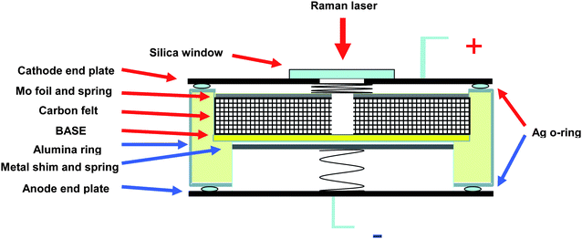 | ||
| Fig. 1 Schematic of a single cell. | ||
The assembled cells were heated in air to 150 °C. The galvanostatic discharge/charge tests were carried out with a BT-2000 Arbin Battery Testing system. The cells were initially discharged down to 1.2 V at 1 mA (≈0.33 mA cm−2). The cells were then charged back to the cut-off voltage of 2.3 V under the same current. After the initial charge/discharge, the cells were cycled under the current of 7 mA (≈2.33 mA cm−2) with the voltage limits of 2.3 and 1.2 V. In order to study the mechanisms of discharge/charge reactions, in situ Raman measurements were carried out during battery operation. Modification of a regular single cell was made for the Raman study, as shown in Fig. 1. The carbon felt in the cathode chamber was cut with a hole (5 mm) in the center for the Raman laser to penetrate into the BASE/cathode interface. The cathode end cap plate was cut with a hole as well and sealed with a silica window. Raman spectra were collected using a spectrometer (Princeton Instruments, Spectrapro2500i) with a back illuminated charge-coupled detector attachment (Princeton Instruments, Spec 10). Raman measurements were performed using an argon-ion laser with a wavelength of 514.5 nm and 20 mW laser power as the excitation source. To control the exposure time, the laser beam was chopped using a mechanical shutter. Raman spectra were obtained by accumulating 10 measurements, with an exposure time of 20 s.
Results and discussion
Fig. 2 shows the temperature dependence of solubility characteristics of elemental sulfur in various types of glymes. The solubility of sulfur in three glymes was quite low at room temperature; however, it increased almost linearly with temperature and reached around 2.3 M at 150 °C, which was in agreement with the literature.22,23 Solubility of Na2S4 and Na2S at 150 °C is illustrated in Table 1, which was one and two orders of magnitude lower than that of sulfur, respectively. According to Fig. 2 and Table 1, there was no dramatic difference in solubility between the selected glymes, which was consistent with the literature.22 Considering its higher boiling point compared to triglyme and butyl diglyme, tetraglyme was, therefore, selected as the solvent for the catholyte for the following studies. The solubility of various polysulfides in tetraglyme is listed in Table 2. A stoichiometric amount of S was mixed with Na2S4 with the intention of formation of Na2Sn with n > 4. The composition of the mixture will be discussed later with the Raman results. It can be seen that the solubility increased exponentially with the sulfur content in the sodium polysulfides. For example, the solubility value for Na2S4 + 4 S was higher than 4.1 M at 150 °C and it was equivalent to more than 32 M of sulfur dissolved in the catholyte, which was more than one order of magnitude higher than that of elemental sulfur itself (see Fig. 2). The extremely high solubility of Na2Sn with n > 4 might be attributed to the loose long-chain sulfur polymer structure in the tetraglyme solution.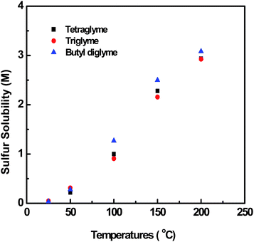 | ||
| Fig. 2 Solubility of elemental sulfur in various types of glymes. | ||
| Na2S | Na2S4 | Na2S4 + S | Na2S4 + 2 S | Na2S4 + 3 S | Na2S4 + 4 S | Na2S4 + 7 S | S |
|---|---|---|---|---|---|---|---|
| a Unit: M. | |||||||
| 0.04 | 0.19 | 0.55 | 1.3 | 2.2 | >4.1 | >5 | 2.3 |
| (∼0.04 S) | (∼0.76 S) | (∼2.8 S) | (∼7.8 S) | (∼15 S) | (>32 S) | (>55 S) | |
Fig. 3 shows the voltammetric behaviors of tetraglyme solutions with and without the addition of polysulfide compound. The background CV curve of tetraglyme is exhibited in Fig. 3a. The current magnitude was extremely low and there were no current peaks on the curve, indicating that tetraglyme itself was quite stable within the voltage window of 0 to 3.5 V vs. Na/Na+. With the addition of 1 M NaI into the solution, the curve showed two pairs of redox peaks at the voltages above 2.5 and below 2 V, respectively. Since there were no peaks observed in the blank solution, these peaks were apparently related to NaI. The redox peak above 2.5 V was likely due to the oxidation and reduction of iodide ion, while that below 2 V was attributed to deposition and oxidation of sodium. From Fig. 3a, it can be seen that with the addition of NaI salt into tetraglyme solution, the electrochemical window of the solution narrowed down to the range of 1 to 2.5 V. No peaks appeared with another CV scan within the voltage range of 1 to 2.5 V (see the black curve in Fig. 3b), which confirmed that the tetraglyme plus NaI system was electrochemically stable within these voltage limits. After 0.05 M Na2S4 was further added into the NaI–tetraglyme solution, two pairs of redox couples were observed in the curve with peaks at around 2.22 and 1.75 V, respectively, which were clearly due to the redox reactions of polysulfide species. Peaks at similar positions were reported by Park et al.12 and Fielder and Singer.24 In an electrochemical study of Na2S4 in N,N-diethylacetamide with 0.1 M NaBF4 as the supporting electrolyte, two pairs of redox peaks in the similar positions were also observed in the CV curves.24
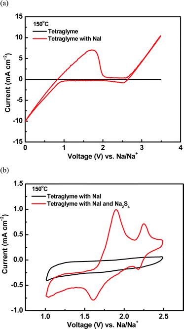 | ||
| Fig. 3 (a) CV curves of tetraglyme solutions with and without addition of NaI in the voltage range from 0 to 4 V. (b) CV curves of tetraglyme plus NaI solution with and without addition of Na2S4 in the voltage range from 1.0 to 2.5 V. | ||
According to the solubility test, Na2Sn with n > 4 showed much higher solubility than elemental sulfur in tetraglyme, therefore, the mixture of S and Na2S4 was selected as the starting cathode material and dissolved into the catholyte of tetraglyme containing 1 M NaI (the purpose of NaI will be discussed later). The Na–S cell tests were carried out with a discharge down to 1.2 V under the current of 1 mA (≈0.33 mA cm−2). The cells were then charged back to the cut-off voltage of 2.3 V under the same current. The cut-off voltage limits were selected based on the safe electrochemical window for the catholyte in Fig. 3a and b. The initial discharge and charge curves of a Na–S cell at 150 °C are shown in Fig. 4. The first discharge capacity was about 473 mA h g−1, which was similar to the reports for room-temperature Na–S batteries.23,25 There were mainly two regions observed in the discharge voltage curve, i.e., a slope region with the voltage between 2.13 and 1.82 V and a plateau at 1.82 V, which indicated that multiple steps and cell reactions occurred during discharge. The charge profile was quite similar to that of discharge. These results were consistent with the voltammetric behavior in Fig. 3b in which at least two redox reactions for the polysulfide occurred at the voltages around 2.22 and 1.75 V. According to the CV and cell test results, the sulfur cathode showed very good reversibility with the tetraglyme catholyte in the current Na–S battery.
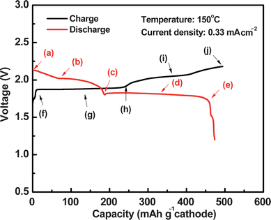 | ||
| Fig. 4 Initial discharge and charge curves of a Na–S battery at 150 °C. | ||
To investigate the discharge and charge reaction mechanisms, a Na–S cell was stopped at various discharge/charge stages. The cathode was analyzed using in situ Raman spectroscopy, during which the cell open circuit voltages (OCVs) were recorded accordingly. The Raman spectrum of the cathode before initial discharge was characterized by two main bands at 441 and 477 cm−1 (see Fig. 5a). Considering that the starting materials in the cathode were Na2S4 and S, these bands might be related to Na2S4, S or Na2Sn with n > 4. The Raman spectra of Na2S4 and S in tetraglyme were obtained in a separate experiment, and the main bands were identified at around 449 and 491 cm−1 for Na2S4 and 477 cm−1 for S, respectively, which were in agreement with the literature.26–28 The band at 477 cm−1 in Fig. 5a was therefore ascribed to elemental sulfur, while that at 441 cm−1 was apparently not from Na2S4 in the current study; instead, it could be due to the formation of α-Na2S5 according to El Jaroudi et al.27,29 In their study, heating a mixture of Na2S or Na2S2 with S resulted in the formation of α-Na2S4 with intermediate species of α- or β-Na2S2, and α-Na2S4 further reacted with excess S to form Na2S5 due to the polymerization–depolymerization mechanism.30 The band at 441 cm−1 in Fig. 5a was quite close to that of 443 cm−1 for α-Na2S527,29 and it was, therefore, assigned to the formation of α-Na2S5. It was concluded that the cathode before initial discharge was a mixture of Na2S5 and S instead of Na2S4 and S.
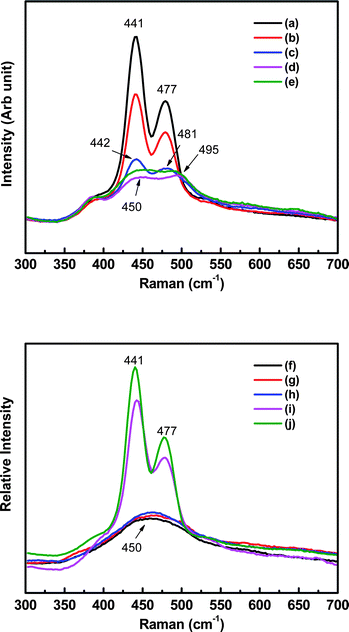 | ||
| Fig. 5 Raman spectra of the Na–S battery cathode at various discharge/charge stages which were marked in Fig. 3. | ||
The bands became broad and shifted to the high-wavenumber side during discharge (see Fig. 5a–e), which indicated that new sulfur species such as Na2S4, Na2S3 or Na2S2 might form. These new species show much lower solubility in tetraglyme, which caused lower Raman intensity in Fig. 5c–e. As discussed earlier, Na2S4 could not co-exist with elemental sulfur, therefore it can only appear after sulfur was consumed. Actually, from Fig. 5a–d, it can be clearly seen that the sulfur lattice line at 477 cm−1 gradually disappeared and, meanwhile, another line at 495 cm−1 from Na2S4 appeared (Fig. 5d). Simultaneously, the lattice line for Na2S5 at 441 cm−1 gradually shifted rightward to 450 cm−1, indicating the reduction of Na2S5 to Na2S4 and Na2S2.27,28 In summary, the sulfur species were formed in the following sequence during discharge: Na2S5 + S → Na2S5 + Na2S4 → Na2S4 + Na2S2, which was in agreement with the Na–S phase diagram.31,32
As mentioned earlier, 1 M NaI was added into tetraglyme to increase ionic conductivity of the catholyte. To verify the effect of NaI on cell performance, a cell without addition of NaI was verified and compared with that containing NaI (see Fig. S1†). It can be seen that there was no obvious difference during the start of discharge in the voltage profile. It was reasonable since the discharge started with Na2S5 + S, which exhibits high solubility in tetraglyme and, thus, led to a high ionic conductivity for the catholyte. Therefore, the effect of NaI on the cell performance was negligible at this stage. However, significant differences were observed during further discharge (e.g. the end of the slope and following plateau regions). During these stages, species such as Na2S4 and Na2S2 started to form in the cathode. These species show much lower solubility in tetraglyme (see Table 2), which caused much less sodium ions dissolved in the tetraglyme catholyte and, therefore, lower ionic conductivity. It manifested with a significantly higher cell voltage drop and lower capacity compared to that with NaI. Overall, it can be concluded that the addition of NaI into the catholyte was critical for achieving higher cathode utilization rate and cell capacity.
The cell OCVs during discharge were recorded after each Raman measurement and plotted in Fig. 6. There was one slope region along with one plateau region in the OCV curve, which was consistent with the discharge profile in Fig. 4. The OCV started at 2.14 V with the cathode species of Na2S5 and S, and it decreased linearly with the formation of Na2S4. Once Na2S5 and S were converted to Na2S4 and Na2S2, the OCV dropped to 1.84 V and kept almost constant thereafter with the cathode constituents of Na2S4 and Na2S2. The OCV profile was quite similar to that for the high-temperature Na–S battery32 and one main difference was that there was another plateau above 2 V in the latter, which was not observed in the present study.
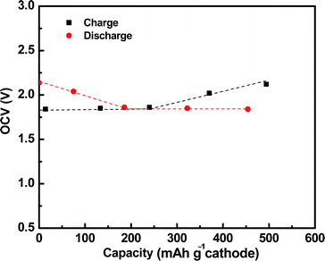 | ||
| Fig. 6 Cell OCVs at various charge/discharge stages. | ||
The Raman spectra during charge are shown in Fig. 5f–j. The broad band at 450 cm−1 was assigned to Na2S4 and Na2S2, and it was split into two bands at 441 and 477 cm−1. The intensity of the two bands significantly increased during charge, indicating the electrochemical oxidation of Na2S4 and Na2S2 to Na2S5 and S. The cell OCVs during charge (also plotted in Fig. 6) were quite similar to that during discharge. All of these results clearly proved the excellent reversibility of sulfur species in the current organic solvent Na–S system.
After the initial discharge/charge cycle at 1 mA (≈0.33 mA cm−2), the Na–S cells were then cycled under the current of 7 mA (≈2.33 mA cm−2) to verify the performance stability. The discharge capacity of the first cycle at the current of 7 mA (i.e., ∼C/8 rate) was around 428 mA h g−1. Compared to the room-temperature Na–S battery reported by Ryu et al.,25 this intermediate-temperature Na–S battery apparently can be cycled under much higher current density and, therefore, a higher C rate. Gordon and Watkins23 also studied a room-temperature Na–S battery with a NASICON electrolyte and tetraglyme as the cathode solvent, respectively. The discharge capacity was around 400 mA h g−1, however, the current density was around 2 orders of magnitude lower than that in the current study. It, therefore, clearly demonstrated that the operating temperature plays a key role regarding battery performance. With the operating temperature increased to 150 °C, satisfactory electrochemical activities can be achieved for both ceramic electrolyte and sulfur species in the cathode, which allows for high rates of mass and electron transfer and, eventually, leads to a higher discharge/charge rate compared to that at room temperature.
The cell voltage profiles of the 1st, 5th, 10th, 20th, 40th and 60th cycles are compared in Fig. 7a. The discharge voltage profile was quite similar to that under lower current density (see Fig. 4) with one slope and one plateau region, while these two regions were not clearly visible during charge. Fig. 7b shows the cell capacity stability during cycling. Obvious capacity loss was observed during the initial 20 cycles. The performance was stabilized thereafter with a lower degradation rate for the following cycles. Overall, more than 70% of the capacity was retained after 60 cycles. The coulombic efficiency of the battery is shown in Fig. S2.† It started from 94% and gradually decreased to around 90% in 60 cycles. The Na–S battery in the current study exhibited much better stability than those of room-temperature Na–S batteries.23,25 Discharge capacity decreased from 538 to 316 mA h g−1 during first two cycles for a room-temperature Na–S battery with tetraglyme as liquid electrolyte,25 which was diagnosed to be related to the dissolution and immigration of sulfur species in the liquid electrolyte, and further irreversible reduction of the species. As mentioned earlier, the dissolution of cathode constituents in the electrolyte is inherent for lower- or room-temperature Na– or Li–S technologies with polymer or organic solvent electrolytes, which inevitably causes rapid cell capacity fade. With a dense β′′-Al2O3 solid electrolyte, however, this type of issue was significantly suppressed. For example, the degradation rate was around 20% for the initial 20 cycles and it slowed down with only 10% for the next 40 cycles (see Fig. 7). It was also noticed that a higher capacity fade rate was observed for the plateau region than the slope region during cycling (see Fig. 7a). As discussed earlier, the plateau region in the voltage profile was related to the formation of polysulfides such as Na2S4 and Na2S2 and these species showed extremely low solubility in tetraglyme. The cell capacity fade in this region could be attributed to the cathode microstructure change such as segregation of these species, which became more and more inaccessible for the electrochemical reactions and led to performance degradation with time. Clearly, more work needs to be carried out to study the degradation mechanism and further improve the cell stability.
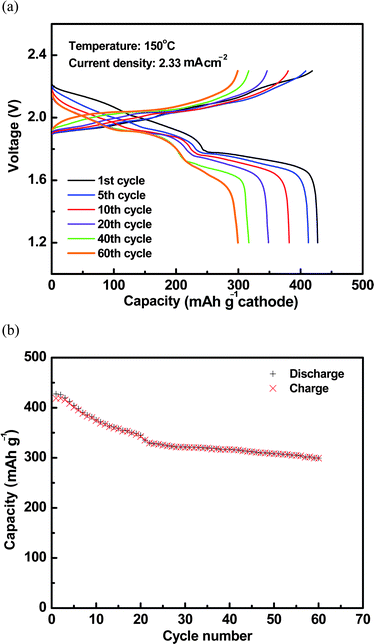 | ||
| Fig. 7 (a) Cell voltage profiles during the 1st, 5th, 10th, 20th, 40th, and 60th cycles at 150 °C. (b) Cycling stability of cell discharge/charge capacities at 150 °C. | ||
Conclusions
An advanced intermediate-temperature Na–S battery with tetraglyme as the catholyte solvent was proposed and evaluated. The solubility of sodium polysulfides in tetraglyme increased exponentially with sulfur content in the composition and was higher than 4.1 M (≈32 M of sulfur) for the mixture of Na2S4 + 4 S at 150 °C. The CV curve of tetraglyme solution with 0.05 M Na2S4 exhibited two pairs of redox couples with the peaks at around 2.22 and 1.75 V, which were due to the redox reactions of polysulfide species. Na–S cells with the mixture of S and Na2S4 as the cathode and tetraglyme plus 1 M NaI as the catholyte were tested at 150 °C. The initial discharge curve showed a slope region and a plateau with a capacity of 473 mA h g−1. The charge profile was similar to that of discharge, indicating good reversibility in the current Na–S chemistry. In situ Raman was carried out to study the discharge/charge reaction mechanisms. It was found from the Raman results that polysulfide species were formed in the following sequence during discharge: Na2S5 + S → Na2S5 + Na2S4 → Na2S4 + Na2S2 and a reverse order during charge, which were consistent with the OCV measurements. This novel battery could be cycled under a much higher C rate compared to room-temperature Na–S batteries owing to its elevated operating temperature and enhanced electrolyte/electrode electrochemical activities. The battery also exhibited much better stability with more than 70% of the capacity retained after 60 cycles, which was attributed to the dense β′′-Al2O3 solid electrolyte that can fully block the inter-diffusion and side reactions between the electrodes. More work will be carried out to further improve the cell performance.Acknowledgements
The work was supported by the Laboratory-Directed Research and Development (LDRD) Program of the Pacific Northwest National Laboratory (PNNL) and the U.S. Department of Energy's (DOE's) Office of Electricity Delivery & Energy Reliability (OE). We appreciate useful discussions with Dr Imre Gyuk of the DOE-OE Grid Storage Program. PNNL is a multi-program laboratory operated by Battelle Memorial Institute for the Department of Energy under contract DE-AC05-76RL01830.References
- B. Hayman, J. Wedel-Heinen and P. Brøndsted, MRS Bull., 2008, 33, 343 CrossRef.
- D. Ginley, M. A. Green and R. Collins, MRS Bull., 2008, 33, 355 CrossRef CAS.
- B. S. Lee and D. E. Gushee, Chem. Eng. Prog., 2008, 104, S29 CAS.
- Z. Yang, J. Zhang, M. C. W. Kintner-Meyer, X. Lu, D. Choi, J. P. Lemmon and J. Liu, Chem. Rev., 2011, 111, 3577 CrossRef CAS.
- Electrical Storage Association, http://www.electricitystorage.org/ESA/technologies/.
- J. T. Kummer and N. Weber, US Pat. 3,413,150, 1968.
- J. L. Sudworth and A. R. Tilley, The Sodium Sulphur Battery, Chapman & Hall, London, 1985 Search PubMed.
- X. Lu, G. Xia, J. P. Lemmon and Z. Yang, J. Power Sources, 2010, 195, 2431 CrossRef CAS.
- Z. Wen, Z. Gu, X. Xu, J. Cao, F. Zhang and Z. Lin, J. Power Sources, 2008, 184, 641 CrossRef CAS.
- M. Liu, Degradation of Sodium β′′-alumina Electrolyte in Contact with Sulfur/Sodium Polysulfide Melts, Lawrence Berkeley Laboratory, Report, 1986, LBL-21563 Search PubMed.
- C. W. Park, H. S. Ryu, K. W. Kim, J. H. Ahn, J. Y. Lee and H. J. Ahn, J. Power Sources, 2007, 165, 450 CrossRef CAS.
- C. W. Park, J. H. Ahn, H. S. Ryu, K. W. Kim and H. J. Ahn, Electrochem. Solid-State Lett., 2006, 9, A123 CrossRef CAS.
- J. S. Kim, H. J. Ahn, I. P. Kim, K. W. Kim, J. H. Ahn, C. W. Park and H. S. Ryu, J. Solid State Electrochem., 2008, 12, 861 CrossRef CAS.
- J. Wang, J. Y. Y. Nuli and R. Holze, Electrochem. Commun., 2007, 9, 31 CrossRef CAS.
- H. Ryu, T. Kim, K. Kim, J. H. Ahn, T. Nam, G. Wang and H. J. Ahn, J. Power Sources, 2011, 196, 5186 CrossRef CAS.
- X. Lu, unpublished data.
- X. Lu, G. W. Coffey, K. D. Meinhardt, V. L. Sprenkle, Z. Yang and J. P. Lemmon, ECS Trans., 2010, 28, 7 CrossRef CAS.
- X. Lu, J. P. Lemmon, V. L. Sprenkle and Z. Yang, JOM, 2010, 62, 31 CrossRef CAS.
- X. Lu, G. Li, J. Y. Kim, J. P. Lemmon, V. L. Sprenkle and Z. Yang, J. Power Sources, 2012, 215, 288 CrossRef CAS.
- X. Lu, G. Li, J. Y. Kim, J. P. Lemmon, V. L. Sprenkle and Z. Yang, Energy Environ. Sci., under review Search PubMed.
- A. Vanzyl, M. M. Thackeray, G. K. Duncan, A. I. Kingon and R. O. Heckroodt, Mater. Res. Bull., 1993, 28, 145 CrossRef CAS.
- S. F. Sciamanna and S. Lynn, Ind. Eng. Chem. Res., 1988, 27, 485 CrossRef CAS.
- J. H. Gordon and J. J. Watkins, US Pat. Application 20100239893A1, 2010.
- W. L. Fielder and J. Singer, Solubility, stability, and Electrochemical Studies of Sulfur-Sulfide Solutions in Organic Solvents, NASA Technical Paper 1245, 1978 Search PubMed.
- H. Ryu, T. Kim, K. Kim, J. Ahn, T. Nam, G. Wang and H. Ahn, J. Power Sources, 2011, 196, 5186 CrossRef CAS.
- A. T. Ward, J. Phys. Chem., 1968, 72, 4133 CrossRef CAS.
- O. El Jaroudi, E. Picquenard, N. Gobeltz, A. Demortier and J. Corset, Inorg. Chem., 1999, 38, 2917 CrossRef CAS.
- G. J. Janz, J. R. Downey, E. Roduner, G. J. Wasilczyk, J. W. Coutts and A. Eluard, Inorg. Chem., 1976, 15, 1759 CrossRef CAS.
- O. El Jaroudi, E. Picquenard, A. Demortier, J. P. Lelieur and J. Corset, Inorg. Chem., 2000, 39, 2593 CrossRef CAS.
- P. D. Bartlett, G. Lohaux and C. D. Weis, J. Am. Chem. Soc., 1958, 80, 5064 CrossRef CAS.
- J. Sangster and A. D. Pelton, J. Phase Equilib., 1997, 18, 89 CrossRef CAS.
- T. Oshima, M. Kajita and A. Okuno, Int. J. Appl. Ceram. Technol. Technol., 2004, 1, 269 CAS.
Footnotes |
| † Electronic supplementary information (ESI) available. See DOI: 10.1039/c2ee23606k |
| ‡ Present address: UniEnergy Technologies, LLC, 4333 Harbour Pointe Blvd SW, Mukilteo, WA 98275, USA. |
| This journal is © The Royal Society of Chemistry 2013 |
