Light-recycling within electronic displays using deep red and near infrared photoluminescent polarizers
Amador
Menéndez-Velázquez
*a,
Carlijn L.
Mulder
a,
Nicholas J.
Thompson
b,
Trisha L.
Andrew
a,
Philip D.
Reusswig
a,
Carmel
Rotschild
a and
Marc A.
Baldo
a
aDepartment of Electrical Engineering and Computer Science, Massachusetts Institute of Technology, 77 Massachusetts Avenue, Cambridge, MA 02139, USA. E-mail: amador@mit.edu; Fax: +1 617 324 5275; Tel: +1 617 253 0085
bDepartment of Materials Science and Engineering, Massachusetts Institute of Technology, 77 Massachusetts Avenue, Cambridge, MA 02139, USA
First published on 25th October 2012
Abstract
We report a linearly polarized luminescent solar concentrator with broad absorption across the visible, and luminescence beyond the emissive spectrum of the display. When used to replace a conventional polarizer in a luminescent display, this device recycles light absorbed by the polarizer, guiding it to the frame of the display where solar cells may be mounted.
Broader contextWe report an energy harvesting scheme for video displays that transforms these ubiquitous devices into solar cells with no loss in display quality. The scheme relies on a similarity between solar cells and emissive displays: both must absorb incident light. In displays, the absence of reflections from the screen ensures that images are still visible even in bright ambient conditions, and that dark colors are not washed out in sunlight. Displays absorb incident light using linear polarizers. Rather than wasting this energy as heat, here, we redirect light to the edges of the display where it can be converted by solar cells. Previously, the weakness of this approach has been that some of the redirected light can be emitted from the display, potentially corrupting the image. In this work, we have solved this problem by shifting the emission into the deep red and near infrared. The concept has particular promise in mobile devices where it may extend the battery life by harvesting ambient light and recycling the display's own backlight. |
Introduction and motivation
Emissive displays such as liquid crystal displays1 (LCDs) and organic light emitting devices2 (OLEDs) now occupy almost the entire front surface of modern portable electronics. To improve their contrast ratio and image quality, these displays are designed to absorb rather than reflect incident light. In LCDs,3 they also must absorb the unwanted polarization component of the backlight. Typically both the ambient light and backlight absorbed in linear polarizers are wasted as heat. Here, we demonstrate linear polarizers that re-emit absorbed light and waveguide it to the edges of the display, where solar cells can convert it into electricity. This approach exploits the principles of a luminescent solar concentrator (LSC) to harvest energy from the ambient or backlight while hiding the solar cells in the frame of the device, leaving the entire front surface available to the display, without sacrificing the contrast ratio or resolution. Unlike previous linearly polarized LSCs,4 the emission in this device occurs at the near infrared, where it can be filtered out without degrading image quality. This is a crucial step closer to practical energy harvesting in displays.Strategy and device characteristics
Concept
A luminescent solar concentrator4–15 (LSC) consists of a piece of glass or plastic plate coated with luminescent centers that absorb sunlight and emit it at a longer wavelength. A substantial part of the longer-wavelength light is trapped by total internal reflection and guided to the edges of the LSC plate, where it is absorbed by small-area photovoltaic cells. Conventional solar concentrators use randomly oriented lumophores. But organic dyes are often dichroic in absorption, which allow us to control the properties of the absorbed and transmitted light by aligning the dyes in a specific direction.4,7,16A conventional linear polarizer is fabricated by mechanically stretching a polymer film, such as polyvinyl alcohol (PVA) doped with iodine or dichroic materials.17 Iodine complexes or dichroic dyes uniaxially oriented along the stretched polymer selectively absorb the incident light with parallel polarization. The remaining transmitted light is perpendicularly polarized.
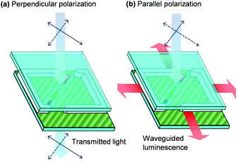
Our linearly polarized luminescent solar concentrators (LP-LSCs) are dye-doped liquid crystals. But in order to recycle the light we replace the purely absorptive dyes in conventional polarizers by a combination of four different fluorescent dichroic molecules with rod-like molecular structures, and long molecular axes almost parallel to the transition moment of the light absorption. Dyes and liquid crystals form a guest–host system. Liquid crystal hosts are used to force the dye molecules to be aligned when the whole system is sandwiched between two glass substrates with anti-parallel rubbing alignment layers. Cooperative uniaxial planar alignment of the fluorescent dichroic molecules in the mixture of liquid crystals leads to polarized absorption (see Fig. 1).
 | ||
| Fig. 1 Orientation of fluorescent and dichroic dye molecules along the direction of rubbed polyamide channels by liquid crystal induced alignment. This configuration allows a luminescent solar concentrator to work as a polarizer. (a) Light with perpendicular polarization to the fluorescent dye molecules is transmitted. (b) Light with parallel polarization to the fluorescent dye molecules is captured and then reemitted and waveguided to the edges. | ||
Materials and optical properties
Our host matrix is MLC-2091 (Merck), which is a mixture of very non-polar nematic liquid crystals and well aligns our dye mixture. Molecules to be used as absorptive dyes in a linearly polarized luminescent solar concentrator must fulfill a number of specifications: (i) dyes must have high dichroic ratios to maximize absorption of light with an electrical field polarized parallel to the transition moment while minimizing absorption of light perpendicularly polarized. (ii) Dyes must be highly fluorescent, especially the terminal dye in a multiple dye system with cascading energy transfer. For intermediate dyes coupled by Förster resonance energy transfer (FRET), high quantum yield maximizes the Förster radii but is not strictly mandatory since FRET can outcompete non-radiative losses.18 (iii) The terminal, emissive dye should show a large spectral shift (Stokes shift) between absorption and emission to minimize self-absorption of the waveguided light. (iv) Dyes should exhibit broad absorption in the visible spectrum. (v) Since dyes normally increase the viscosity of the host nematic mixture, a low concentration is desirable in order to reach a better alignment. Therefore, chromophores with a high absorption coefficient and a good solubility in the liquid crystal host are required. (vi) Solubility is especially critical at low temperatures, where the long aromatic dye molecules generally have a pronounced tendency to crystallize out of the nematic mixture. (vii) Dyes must be linear in order that they can be aligned using liquid crystals. (viii) We also observed that non-ionic dyes were significantly more stable in our host liquid crystals.We combined four dyes to cover the visible spectrum with the exception of a gap at 600 nm. The selected dyes are 3-(2-benzothiazolyl)-N,N-diethylumbelliferylamine (coumarin 6), (E)-2-(2-(2-(1,2,3,5,6,7-hexahydropyrido[3,2,1-ij]quinolin-9-yl)vinyl)-6-methyl-4H-pyran-4-ylidene)malononitrile (DCM2), 9-diethylamino-5 benzo[α]phenoxazinone (Nile Red) and a squaraine dye (1,3-bis[4-(dioctylamino)-2-hydroxyphenyl]-2,4-dihydroxycyclobutenediylium dihydroxide, bis(inner salt)).
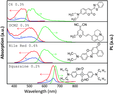
The chemical structure, absorption, and emission spectra of these dyes are shown in Fig. 2. The concentrations of each dye (in weight% with respect to the liquid crystal host) are C6 0.3%, DCM2 0.3%, Nile Red 0.6% and squaraine dye 0.2%, both in the devices with just one dye and in the resulting device with multiple dyes. The dyes form a near-field energy transfer cascade to the terminal squaraine dye, which emits in the deep red and near infrared.
 | ||
| Fig. 2 Absorption for parallel (red line) and perpendicular (blue line) polarizations and PL (green line) of four different LP-LSCs with one dye and MLC-2091 as a host material. The concentration of each dye is the same as that of the concentration of the dye in the LP-LSC with multiple dyes. | ||
The absorption of each dye was measured for perpendicular and parallel polarizations. As expected, we find the maximum absorption for parallel polarized light. The order parameter provides a measurement of the degree of alignment of the different dyes. It is defined as S = (A‖ − A⊥)/(A‖ + 2A⊥), where A‖ and A⊥ are the absorbances parallel and perpendicular to the orientation of the long axis of the chromophores, respectively. It takes the values 0.45 (C6), 0.30 (DCM2), 0.25 (Nile Red) and 0.49 (squaraine dye). Consistent with the steric properties of each dye, the squaraine dye is found to have the best alignment, and Nile Red the worst.
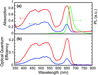
The photoluminescence and spectrally resolved absorption of the complete device with all four dyes combined is shown in Fig. 3a. The absence of emission from C6, DCM2 and Nile Red confirms that multistep cascade Förster resonance energy transfer6,19 funnels energy to the terminal dye. In this case, the order parameter takes the values 0.32 (C6), 0.25 (DCM2), 0.30 (Nile Red) and 0.42 (squaraine dye) at the peak absorption wavelength of the respective dyes. When multiple dyes are combined, the polarization dependence of the absorption spectrum shows cooperative effects that improve the alignment of the Nile Red dye but degrade the alignment of the other dyes. Significant improvements in the polarization selectivity are likely with targeted molecular design of the hosts and lumophores.
 | ||
| Fig. 3 (a) Absorption for parallel (red line) and perpendicular (blue line) polarizations and PL (green line) of a device with multiple dyes and a MLC-2091 liquid crystal host (C6 0.3 wt%, DCM2 0.3 wt%, Nile Red 0.6 wt%, squaraine 0.2 wt%). (b) Optical quantum efficiency versus wavelength of the device for incident light with parallel (red line) and perpendicular (blue line) polarizations. | ||
The key performance parameter for luminescent solar concentrators is the optical quantum efficiency, OQE, defined as the fraction of photons coupled to the edges of the LSC (see Fig. 3b). At the peak absorption wavelengths, around 20% of the incident photons are recycled and waveguided to the edges. The photoluminescent quantum yield of the terminal squaraine dye is 34% (measured in a 0.5 wt% squaraine in PMMA solution). Comparisons between our measurement of the overall optical quantum efficiency and expectations based on the quantum yield of the squaraine in PMMA, suggest that the terminal dye's performance is similar in the liquid crystal host.
The optical quantum efficiency of a LP-LSC with just this terminal squaraine dye and MLC-2091 as the host material at the peak absorption wavelength is 24%, pretty close to the 23% OQE of this dye in the multiple dye system. This reveals that the optical performance of the squaraine dye is not degraded when combined with other dyes in a multiple dye system.
The optical trapping efficiency is approximately 66% for horizontal dipoles embedded in a waveguide consisting of glass and a liquid crystal with a refractive index, n ∼ 1.5.7 Given the squaraine's photoluminescent yield of 34%, and with 90% optical absorption, the theoretical OQE is 20%, in good agreement with the data. This confirms that: (i) there are no significant self-absorption losses in this test device with its relatively small geometric gain, G = 2.7, and (ii) the dye loadings and overlap between absorption and emission along the cascade of intermediate dyes ensure Förster resonant energy transfer to the terminal dye with approximately unity efficiency.
The OQE measurement demonstrates that about 20% of the incident parallel-polarized photons are recycled and waveguided into the edges, but this is just for a single polarizer. Electronic displays use two crossed polarizers which can capture ambient light. We expect that a polarized luminescent filter coupled to solar cells could generate an excess of 10 μW cm−2 under typical office lighting conditions4 (400 lux). Power generation outdoors can be much larger: 1–10 mW cm−2. And in the case of LCD displays, they can also recycle the backlight of the display. The combination increases the overall efficiency of the display, recycling light, saving energy and increasing the duration of the battery.
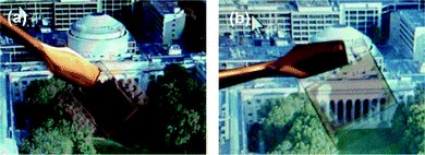
Fig. 4 shows the effect of a LP-LSC working as a polarizer. We present two photographs of a computer screen in front of which a LP-LSC was placed. The emission of the display is linearly polarized, and consequently we observe modulation in the optical transmission as the polarizer is rotated from the absorptive parallel orientation (Fig. 4a) to higher transparency (Fig. 4b) when they are perpendicular.
 | ||
| Fig. 4 Linearly polarized luminescent solar concentrator with the dye molecules parallel (a) or perpendicular (b) to the molecular orientation of the LCD display. | ||
Experimental details
Device fabrication
Dyes are dissolved in chloroform and mixed with the liquid crystal MLC-2091 (Merck), maintaining the solution at 60 °C for five minutes. The solution is then placed within a desiccator for 12 hours to evaporate the solvent. The liquid crystal and the dye molecules are aligned on rubbed polyamide surfaces using liquid crystal cells from Instec (see Fig. 1). They are composed of two pieces of 15.25 mm × 17.00 mm × 1.5 mm glass, with a cell gap of 5 μm. There are two openings on Instec liquid crystal cells. We put a small amount of material on one opening of the empty cell. The capillary force pulls the liquid crystal material and dyes into the empty cell. It takes a few minutes before the cell is fully filled. To accelerate the filling process, all the materials were heated to 70 °C, which is above the isotropic phase transition temperature of the liquid crystal mixture. Once the cell is filled, it is slow cooled, especially near the phase transition temperature, in order to ensure good alignment.Optical measurements
The optical quantum efficiency is characterized within an integrating sphere. We discriminate between edge and facial LSC emission by selectively blocking the edge emission with a black marker and tape in the glass edges and in the interfaces of the two glasses. The spectrally resolved measurements use a 150 W xenon lamp. That is coupled to a monochromator and chopped at 73 Hz. The photoluminescence for the OQE measurements is detected by a Si photodetector mounted directly on the integrating sphere and which in turn is connected to a lock-in-amplifier.Conclusions
To provide sufficient contrast, displays must absorb incident light, as well as the backlight in LCDs in order to display the specific information content. Consequently, they offer significant opportunity for energy harvesting, especially in mobile devices. Both linearly polarized LSCs and linearly polarized solar cells have been proposed for use in energy harvesting displays.4,20 Unlike polarized solar cells, LSCs do not need bus bars to direct electrical power on the surface of the display. However, LSCs can also degrade display quality if any re-emitted radiation is observed by the user. The solution demonstrated here shifts the emission from the LSC beyond the emissive spectrum of a typical display, λ > 650 nm, where it can be safely filtered. The squaraine dye employed here is also dichroic and relatively photoluminescent. Consequently, we have demonstrated that the squaraine family of dyes is especially attractive as the basis of future work on this application.Acknowledgements
This work was supported as part of the Center for Excitonics, an Energy Frontier Research Center funded by the U.S. Department of Energy, Office of Science, Office of Basic Energy Sciences under Award Number DE-SC0001088. A.M. also thanks ITMA Materials Technology.Notes and references
- R. H. Chen, Liquid Crystal Displays: Fundamental Physics and Technology, Wiley, 2011 Search PubMed.
- T. Tsujimura, OLED Display Fundamentals and Applications, Wiley, Hoboken, NJ, 2011 Search PubMed.
- S. Kobayashi, S. Mikoshiba and S. Lim, LCD Backlights, Wiley, 2009 Search PubMed.
- C. L. Mulder, P. D. Reusswig, A. P. Beyler, H. Kim, C. Rotschild and M. A. Baldo, Opt. Express, 2010, 18, A91–A99 CrossRef CAS.
- W. H. Weber and J. Lambe, Appl. Opt., 1976, 15, 2299–2300 CrossRef CAS.
- M. J. Currie, J. K. Mapel, T. D. Heidel, S. Goffri and M. A. Baldo, Science, 2008, 321, 226–228 CrossRef CAS.
- C. L. Mulder, P. D. Reusswig, A. M. Velazquez, H. Kim, C. Rotschild and M. A. Baldo, Opt. Express, 2010, 18, A79–A90 CrossRef CAS.
- C. L. Mulder, L. Theogarajan, M. Currie, J. K. Mapel, M. A. Baldo, M. Vaughn, P. Willard, B. D. Bruce, M. W. Moss, C. E. McLain and J. P. Morseman, Adv. Mater., 2009, 21, 1–5 CrossRef.
- V. Fattori, M. Melucci, L. Ferrante, M. Zambianchi, I. Manet, W. Oberhauser, G. Giambastiani, M. Frediani, G. Giachi and N. Camaioni, Energy Environ. Sci., 2011, 4, 2849–2853 CAS.
- M. G. Debije and P. P. C. Verbunt, Adv. Energy Mater., 2012, 12–35 CrossRef CAS.
- H. Hernandez-Noyola, D. H. Potterveld, R. J. Holt and S. B. Darling, Energy Environ. Sci., 2012, 5, 5798–5802 CAS.
- J. Bomm, A. Büchtemann, A. J. Chatten, R. Bose, D. J. Farrell, N. L. A. Chan, Y. Xiao, L. H. Slooff, T. Meyer, A. Meyer, W. G. J. H. M. vanSark and R. Koole, Sol. Energy Mater. Sol. Cells, 2011, 95, 2087–2094 CrossRef CAS.
- S. J. Gallagher, B. Norton and P. C. Eames, Sol. Energy, 2007, 81, 813–821 CrossRef CAS.
- K. Barnham, J. L. Marques, J. Hassard and P. O'Brien, Appl. Phys. Lett., 2000, 76, 1197–1199 CrossRef CAS.
- A. J. Chatten, K. W. J. Barnham, B. F. Buxton, N. J. Ekins-Daukes and M. A. Malik, Sol. Energy Mater. Sol. Cells, 2003, 75, 363–371 CrossRef CAS.
- P. P. C. Verbunt, A. Kaiser, K. Hermans, C. W. M. Bastiaansen, D. J. Broer and M. G. Debije, Adv. Funct. Mater., 2009, 19, 2714–2719 CrossRef CAS.
- W. J. Gunning and J. Foschaar, Appl. Opt., 1983, 22, 3229–3231 CrossRef CAS.
- S. E. Braslavsky, E. Fron, H. B. Rodriguez, E. S. Roman, G. D. Scholes, G. Schweitzer, B. Valeur and J. Wirz, Photochem. Photobiol. Sci., 2008, 7, 1444–1448 CAS.
- S. T. Bailey, G. E. Lokey, M. S. Hanes, J. D. M. Shearer, J. B. McLafferty, G. T. Beaumont, T. T. Baseler, J. M. Layhue, D. R. Broussrd, Y. Z. Zhang and B. P. Wittmershaus, Sol. Energy Mater. Sol. Cells, 2007, 91, 67–75 CrossRef CAS.
- R. Zhu, A. Kumar and Y. Yang, Adv. Mater., 2011, 23, 4193–4198 CrossRef CAS.
| This journal is © The Royal Society of Chemistry 2013 |
