Non-precious Co3O4 nano-rod electrocatalyst for oxygen reduction reaction in anion-exchange membrane fuel cells
Received
7th April 2011
, Accepted 30th September 2011
First published on 2nd November 2011
Abstract
We report preparation of carbon-supported Co3O4 electrocatalysts with nano-rods and spherical structures by the solvent-mediated morphological control method. The catalytic properties of the prepared catalysts for the oxygen reduction reaction (ORR) in alkaline media are investigated. We show that the ORR catalytic activity of the prepared catalysts is sensitive to the number and activity of surface-exposed Co3+ ions that can be tailored by the morphology of cobalt oxides. In particular, we demonstrate that the non-precious Co3O4 electrocatalyst with the nano-rod structure (∼12 nm in length and ∼5.1 nm in diameter) prepared in the mixed solvent of water to dimethylformamide ratio of 1![[thin space (1/6-em)]](https://www.rsc.org/images/entities/char_2009.gif) :
:![[thin space (1/6-em)]](https://www.rsc.org/images/entities/char_2009.gif) 1 exhibits a higher current density than a much more expensive palladium-based catalyst does at the low potential region.
1 exhibits a higher current density than a much more expensive palladium-based catalyst does at the low potential region.
Broader context
The development of non-precious catalysts with high activity and practical durability in oxygen reduction reaction is important to reduce fuel cell costs. Co3O4 can be used as a non-precious ORR electrocatalyst in alkaline media. In general, the ORR is assumed to take place at active sites associated with Co3+ cations at the cobalt oxide surface. These Co3+ ions would act as donor–acceptor reduction sites, with acceptor character with respect to the Co3O4 by capturing electrons and donor electronic properties with respect to O2 in solution. The distribution of the cations among the different coordination sites strongly depends on the shapes and sizes of particles, which is thus a key factor to their ultimate performance and applications. In this article, we report a facile solvent-mediated morphological control method to prepare the carbon-supported Co3O4 electrocatalysts. The results indicate that the ORR catalytic activity of the prepared catalysts is sensitive to the number and activity of surface-exposed Co3+ ions that can be tailored by the morphology of cobalt oxides. The Co3O4 catalyst with the nano-rod structure prepared in the mixed solvent of water to dimethylformamide ratio of 1![[thin space (1/6-em)]](https://www.rsc.org/images/entities/char_2009.gif) : :![[thin space (1/6-em)]](https://www.rsc.org/images/entities/char_2009.gif) 1 exhibits a higher limiting current density than a much more expensive Pd/C catalyst does. 1 exhibits a higher limiting current density than a much more expensive Pd/C catalyst does.
|
1. Introduction
The oxygen reduction reaction (ORR) is an important process in fuel cells and other electrochemical technologies and its kinetics has been extensively studied.1–3 Previous studies have indicated the ORR reaction pathway is highly dependent on electrode materials and reaction media.4–6 Pt is considered as a typical electrocatalyst for the ORR in fuel cells, as it supports the four-electron reduction of oxygen at relatively low overpotentials.5 Recently, with the emergence of anion-exchange membranes (AEM) that conduct hydroxide ions (OH−), direct AEM fuel cells have received increasing attention.7–9 Electrode kinetics particularly for the ORR is faster in alkaline media than that in acid media. In this regard, Pd-based catalysts are emerging as an alternative to Pt-based catalysts for the cathode of direct AEM fuel cells.9–12 Although a bit cheaper than platinum, palladium is also limited by its supply. To become commercially viable, direct AEM fuel cells have to overcome the barrier of high catalyst cost caused by the exclusive use of Pd-based catalysts in the fuel-cell electrodes. The search for non-precious ORR electrocatalysts is, therefore, one of the most active and competitive fields in electrochemistry.
Cobalt oxides (Co3O4) are known to act as non-precious ORR catalysts in alkaline media.13,14 Co3O4 belongs to the normal spinel crystal structure based on a close-packed face centered cubic configuration of O2− ions, in which Co2+ ions occupy the one-eighth of the tetrahedral A sites while Co3+ ions occupy one-half of the octahedral B sites.15 In general, the ORR is assumed to take place at active sites associated with the cations at the oxide surface in a higher oxidation state. These cations would act as donor–acceptor reduction sites, with the acceptor character with respect to the solid by capture of electrons and donor electronic properties with respect to the species in solution.16 The ORR on oxide electrodes has been studied with voltammetry, rotating disk electrode and rotating ring disk electrode measurements and the following two possible parallel pathways for the ORR were suggested:13,16
(i) Direct four electron pathway:
| | | O2(ads) + 2H2O + 4e− ↔ 4OH− (Erev = 0.41 V at pH = 14) | (1) |
(ii) Indirect (peroxide) pathway:
| | | O2(ads) + H2O + 2e− ↔ OH− + HO−2 (Erev = −0.065 V) | (2) |
which are followed by either the further
reduction of
peroxide ions
| | | HO−2 + H2O + 2e− ↔ 3OH− (Erev = 0.867 V at pH = 14) | (3) |
or the
catalytic peroxide decomposition| | | HO−2(ads) → 1/2O2 + OH− | (4) |
Ideally, oxygen reduction should proceed through a four-electron process to yield an efficient reduction of oxygen. It has been reported that a change in the B sites of Co3O4 will change the catalytic activity for the ORR, as the cations placed in these sites play an important role in assisting the chemisorption of O2 through their cationic d-orbitals.15,16
It is understood that the distribution of the cations among the different coordination sites strongly depends on the shapes and sizes of the particles, which is thus a key factor to their ultimate performance and applications.15,17 Co3O4 with different morphologies including nanospheres,18 nanocubes,19 nanofibers,20 nanoclusters,21 mesoporous structures,22 and nanoplatelets23 have been reported for potential applications as sensors, electrochromical devices, magnetic materials and heterogeneous catalysts. However, the work on the morphology-related catalytic activity for ORR on these Co3O4 nanostructures is scarce. Because the ORR is a surface-structure sensitive reaction on electrodes, the exposed active sites of Co3+ ions on the Co3O4 electrocatalyst play a determinant role in the performance for the ORR.16 To enhance the catalytic activity for the ORR, an effective approach is to enhance the exposed Co3+ ions on Co3O4 nanostructures.16 In this work, the solvent-mediated method24 was adopted to achieve the morphology control of Co3O4 nanostructures. The Co3O4 with rod and spherical nanostructures were obtained by changing the mole ratio of the developed mixed solvent of water and dimethylformamide. We demonstrate that the carbon-supported Co3O4 electrocatalyst with the nano-rod structure prepared in the mixed solvent of water to dimethylformamide ratio of 1![[thin space (1/6-em)]](https://www.rsc.org/images/entities/char_2009.gif) :
:![[thin space (1/6-em)]](https://www.rsc.org/images/entities/char_2009.gif) 1 exhibits the highest catalytic activity for the ORR among all the catalyst samples prepared under different conditions. We further show that this particular Co3O4 electrocatalyst exhibits a higher catalytic activity for the ORR than a much more expensive carbon supported noble palladium catalyst does.
1 exhibits the highest catalytic activity for the ORR among all the catalyst samples prepared under different conditions. We further show that this particular Co3O4 electrocatalyst exhibits a higher catalytic activity for the ORR than a much more expensive carbon supported noble palladium catalyst does.
2. Experimental
2.1 Materials and samples preparation
All of the chemicals used were of analytical grade. Palladium nitrate dihydrate was purchased from Aldrich. Cobalt chloride hexahydrate (CoCl2·6H2O), potassium hydroxide, N,N-dimethylformamide (DMF), ethanol, sodium borohydride (NaBH4), and ammonia solution (all from Merck KGaA) were used as received. Vulcan XC-72 carbon powder (particle size 20–40 nm) was procured from E-TEK Company. 5 wt% A3-solution was received from Tokuyama and used as received.
The carbon powder supported Co(OH)2 nanoparticles were prepared as follows: 10 mM of Co2+ precursors were prepared in the mixed solvent of DI water and DMF with the water to DMF mole ratio of 1![[thin space (1/6-em)]](https://www.rsc.org/images/entities/char_2009.gif) :
:![[thin space (1/6-em)]](https://www.rsc.org/images/entities/char_2009.gif) 0, 3
0, 3![[thin space (1/6-em)]](https://www.rsc.org/images/entities/char_2009.gif) :
:![[thin space (1/6-em)]](https://www.rsc.org/images/entities/char_2009.gif) 1, 1
1, 1![[thin space (1/6-em)]](https://www.rsc.org/images/entities/char_2009.gif) :
:![[thin space (1/6-em)]](https://www.rsc.org/images/entities/char_2009.gif) 1 and 1
1 and 1![[thin space (1/6-em)]](https://www.rsc.org/images/entities/char_2009.gif) :
:![[thin space (1/6-em)]](https://www.rsc.org/images/entities/char_2009.gif) 3, respectively; the prepared precursor solution (200 ml in a beaker) was mixed with carbon powder under stirring, after a homogeneous solution was obtained, 30 mL of ammonia solution was added, respectively; after stirring at room temperature, the products were aged for 24 h and the resulting precipitates were centrifuged, followed by washing with distilled water and ethanol, and dried at 60 °C in an oven. The prepared cobalt hydroxides with the metal loading of 20 wt% were denoted by Co(OH)2-10, Co(OH)2-31, Co(OH)2-11 and Co(OH)2-13 with the postfix number for the water to DMF ratio in mixed solvent, respectively. The carbon supported cobalt oxides were obtained by further heat treatment of the cobalt hydroxides at 330 °C for 2 h with the resulted samples denoted by Co3O4-10, Co3O4-31, Co3O4-11 and Co3O4-13, respectively. For comparison, the carbon supported palladium catalyst with a metal loading of 20 wt% was prepared with a method reported elsewhere.25
3, respectively; the prepared precursor solution (200 ml in a beaker) was mixed with carbon powder under stirring, after a homogeneous solution was obtained, 30 mL of ammonia solution was added, respectively; after stirring at room temperature, the products were aged for 24 h and the resulting precipitates were centrifuged, followed by washing with distilled water and ethanol, and dried at 60 °C in an oven. The prepared cobalt hydroxides with the metal loading of 20 wt% were denoted by Co(OH)2-10, Co(OH)2-31, Co(OH)2-11 and Co(OH)2-13 with the postfix number for the water to DMF ratio in mixed solvent, respectively. The carbon supported cobalt oxides were obtained by further heat treatment of the cobalt hydroxides at 330 °C for 2 h with the resulted samples denoted by Co3O4-10, Co3O4-31, Co3O4-11 and Co3O4-13, respectively. For comparison, the carbon supported palladium catalyst with a metal loading of 20 wt% was prepared with a method reported elsewhere.25
2.2 Sample characterizations
Thermogravimetric analyses (TGA) were made using a TA Instrument UNIX/TGA7 (Perkin Elmer). The experiment was performed at 5 °C min−1 from room temperature to 500 °C in nitrogen (99.999%) at a flow rate of 20 mL min−1. The valence state of the prepared samples was carried out by the X-ray photoelectron spectroscopy (XPS) technique, which is equipped with a Physical Electronics PHI 5600 multi-technique system using Al monochromatic X-ray at a power of 350 W. Chemical bonding of cobalt–oxygen was studied by FTIR (FTS 6000, Bio-Rad) using the potassium bromide (KBr) pellet technique. The spectra were measured with a resolution of 4 cm−1 and 32 scans were accumulated. Transmission electron microscopy (TEM) images were obtained by using a high-resolution JEOL 2010F TEM system operating with a LaB6 filament at 200 kV. The samples were dispersed in ethanol under sonication and dropped on the carbon-coated grid and then imaged. The X-ray diffraction (XRD) patterns of the carbon supported Co3O4 catalysts were obtained with a Philips powder diffraction system (model PW 1830) using a Cu Kα source operating at 40 keV at a scan rate of 0.025° s−1.
Electrochemical measurements were carried out by cyclic voltammetry (CV) using a potentiostat (EG&G Princeton, model 273A). A conventional, three-electrode cell consisting of glassy carbon electrode (GCE) with an area of 0.125 cm2 was used as the working electrode, Pt foil was employed for the counter electrode and Hg/HgO/KOH (1.0 M) (MMO, 0.098 V vs. SHE) was used as the reference electrode. The reference electrode was placed in a separate chamber, which is located near the working electrode through a Luggin capillary tube. The working electrode was modified with the catalyst layer achieved by dropping a suitable amount of catalyst ink on the GCE. The catalyst ink was prepared by ultrasonically dispersing 10 mg of the carbon supported catalysts in 1.9 ml of ethanol, to which 0.1 ml of 5 wt% A3-solution was added, and the dispersion was ultrasonicated for 30 min to obtain a homogeneous solution. A quantity of 10 μl of the dispersion was pipetted out on the top of the GCE and dried in air. Solutions were prepared from analytical grade reagents and DI water. CV experiments were done at room temperature in 1.0 M KOH solution saturated with nitrogen. For all of the experiments, stable voltammogram curves were recorded after scanning for 20 cycles in the potential region from 0 to 0.6 V in 1.0 M KOH solution. Polarization curves for the oxygen reduction reaction (ORR) were obtained in 1.0 M KOH solution using the rotating disk electrode (RDE) with the speed controlled by a Metrohm 628-10 unit. Before the RDE study, the electrodes were cycled at 50 mV s−1 between 0 and 0.6 V until reproducible cyclic voltammograms were obtained. Normalized currents are given in terms of geometric (mA cm−2).
3. Results and discussion
3.1 Physicochemical characterizations
Fig. 1 presents the thermogravimetric analyses of cobalt hydroxide samples in nitrogen. It can be seen that all the samples yield weight loss in the measured temperature range. A first weight loss of ∼6.8%, which is attributed to the removal of physisorbed water, occurs between 23 and 115 °C. A second weight loss (∼12.7%), between 120 and 200 °C, is ascribed to the removal of the crystalline water molecules. A third exothermal reaction is observed between 220 and 400 °C. This reaction corresponds to the decomposition of cobalt hydroxides and the formation of cobalt oxide.23 It can be seen in Fig. 1 that the equivalent weight losses were observed for the four samples within 330 °C during the TGA analysis.23,26 In this work, the heat treatment temperature for the cobalt oxides was selected at 330 °C according to the TGA result.
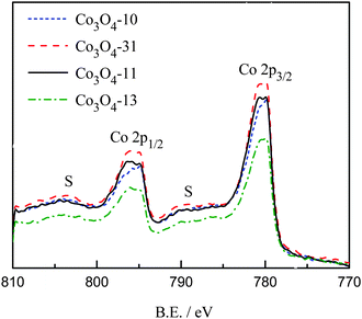
The valence state of the prepared cobalt oxides was investigated by XPS. Fig. 2 shows the regional Co2p spectra of the cobalt oxide samples. The Co2p spectra show a doublet containing a low energy band (Co2p3/2) and a high energy band (Co2p1/2) at 780.4 and 795.6 eV for Co3O4-10 and Co3O4-31, and 780.5 and 795.8 eV for Co3O4-13 and Co3O4-11 samples, respectively. The positions of the peaks are consistent with the results reported elsewhere.27,28
The energy difference between the peak of Co2p3/2 − 2p1/2 splitting is approximately 15 eV, which indicates the presence of both Co2+/Co3+ species in the all the cobalt oxides samples. From Fig. 2, it can be observed that weak 2p satellite features are found at binding energies at 788.9 and 804.3 eV for the prepared cobalt oxides. It has been reported that the weak satellite structures are characteristic of spinel structures in which 3+ cations occupy octahedral lattice sites with diamagnetic, filled t2g and empty eg levels, and 2+ cations are in tetrahedral sites.18,27
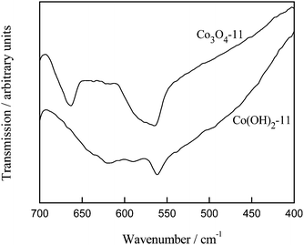
The cobalt oxide formation is also evident in FTIR characterizations. Fig. 3 shows the FTIR spectra of Co(OH)2-11 and Co3O4-11 samples. As compared with the cobalt hydroxide sample, the IR spectrum of the cobalt oxide sample displays two distinct bands that originate from the stretching vibrations of the metal–oxygen bonds.26 The first band at 564 cm−1 is associated with the OB3 vibration in the spinel lattice, where B denotes Co3+ in an octahedral hole. The second band at 662 cm−1 is attributed to the ABO3 vibration, where A denotes the Co2+ in a tetrahedral hole.21,26 The fingerprint of IR absorption at 564 and 662 cm−1 for the Co3O4 spinel phase is fully developed after heat treatment at 330 °C for this sample. The same result was also observed for the other cobalt oxide samples.
The morphology and dispersion of the prepared cobalt oxides were investigated by TEM. Fig. 4 displays the typical TEM images of the samples. As can be seen in Fig. 4a, in the aqueous solution, the prepared cobalt oxides display roughly nano-rod structures. The average dimensions of Co3O4 nano-rods in the Co3O4-10 sample are ∼30 nm in length with a diameter of ∼4.0 nm. In the mixed solvent with the water to DMF ratio of 3 to 1, the shortened Co3O4 nano-rods were obtained, as can be seen in Fig. 4b. The average dimensions of Co3O4 nano-rods in the Co3O4-31 sample are ∼22 nm in length and ∼4.7 nm in diameter. By further increasing the DMF ratio to 1![[thin space (1/6-em)]](https://www.rsc.org/images/entities/char_2009.gif) :
:![[thin space (1/6-em)]](https://www.rsc.org/images/entities/char_2009.gif) 1 in the mixed solvent, the even more shortened Co3O4 nano-rods were achieved in the Co3O4-11 sample with ∼12 nm in length and ∼5.1 nm in diameter. A high-resolution TEM (HRTEM) image is also presented in the inset of Fig. 4c. From this HRTEM image, it can be observed that the crystalline nanorod is formed on the carbon powder during the nucleation and growth process. The TEM image of the Co3O4-13 sample is shown in Fig. 4d. It can be seen that the Co3O4 particles prepared in the water to DMF ratio of 1 to 3 are roughly spherical in shape, the mean particle size of the Co3O4 particles is 10.5 nm. This result indicates that the morphology control of Co3O4 nanostructures was achieved in the developed mixed solvent of water and DMF. It is believed that DMF plays three distinct roles in the mixed solvent system: solvent, pH adjustor and ligand. The pH can be adjusted in the mixed solvent because the anion solvating ability is slower in DMF than that of water, and DMF coordinated Co2+ ions may control the growth direction of crystals serving as structure-directing reagent. The same result was observed in Kumar's work.29 It can be observed from Fig. 4 that the incidental aggregation accrued for the entire carbon supported cobalt oxide samples. This phenomenon may result from the heat treatment process, which was absent in the cobalt hydroxide samples.
1 in the mixed solvent, the even more shortened Co3O4 nano-rods were achieved in the Co3O4-11 sample with ∼12 nm in length and ∼5.1 nm in diameter. A high-resolution TEM (HRTEM) image is also presented in the inset of Fig. 4c. From this HRTEM image, it can be observed that the crystalline nanorod is formed on the carbon powder during the nucleation and growth process. The TEM image of the Co3O4-13 sample is shown in Fig. 4d. It can be seen that the Co3O4 particles prepared in the water to DMF ratio of 1 to 3 are roughly spherical in shape, the mean particle size of the Co3O4 particles is 10.5 nm. This result indicates that the morphology control of Co3O4 nanostructures was achieved in the developed mixed solvent of water and DMF. It is believed that DMF plays three distinct roles in the mixed solvent system: solvent, pH adjustor and ligand. The pH can be adjusted in the mixed solvent because the anion solvating ability is slower in DMF than that of water, and DMF coordinated Co2+ ions may control the growth direction of crystals serving as structure-directing reagent. The same result was observed in Kumar's work.29 It can be observed from Fig. 4 that the incidental aggregation accrued for the entire carbon supported cobalt oxide samples. This phenomenon may result from the heat treatment process, which was absent in the cobalt hydroxide samples.
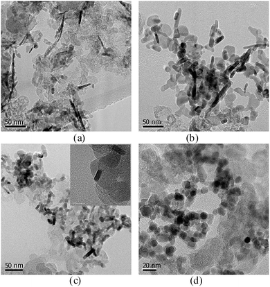 |
| | Fig. 4 TEM images of the cobalt oxides Co3O4-10 (a), Co3O4-31 (b), Co3O4-11 (c) and Co3O4-13 (d). | |
There are no defined Co3O4 characteristic peaks in XRD analysis for both the nano-rods and the spherical nanoparticles (data not shown), the absence of the Co3O4 characteristic peaks may be due to the smaller concentration level and poor crystallinity of the Co3O4 particles. Since the ORR on the Co3O4 involves chemisorption of O2 with surface Co3+ ions,16 the number and activity of these active sites play a determinant role in the catalytic performance. The Co3O4 nanostructures prepared in this work may contain much more structure distortions than crystalline cobalt oxides do.30 Hence, the obtained Co3O4 nanostructures may provide more available sites for the ORR.
3.2 Electrochemical characterizations
As mentioned in Introduction, the ORR is assumed to take place at active sites associated with cations in the higher oxidation state (Co3+) at the cobalt oxide surface. These Co3+ ions would act as donor–acceptor reduction sites, with acceptor character with respect to the Co3O4 by capturing electrons and donor electronic properties with respect to O2 during oxygen reduction reactions.16 Thus, to understand the nature of the active sites present in the carbon supported Co3O4 catalysts, which can be roughly characterized by the Co3+/Co4+ redox profiles of the cyclic voltammetry,16,31 we conducted the CV studies for the cobalt oxide electrodes in the potential range between 0 and 0.6 V in 1.0 M KOH. The CV curves after 20 times cycling are presented in Fig. 5. As can be seen in Fig. 5, during the positive-going scan the current increases rapidly until a current peak is seen for all the catalyst coated electrodes, which correspond to the oxidation of the Co3+ species on the surface of the cobalt oxides. Corresponding to the oxidation process, the cathodic peak, at around 0.5 V, is attributed to the reduction of the Co4+ to Co3+ species.31 These results are characteristic of the surface confined redox couple which can be described with the following reactions,| | | CoOOH + OH− ⇒ CoO2 + H2O + e− | (5) |
| | | CoO2 + H2O + e− ⇒ CoOOH + OH− | (6) |
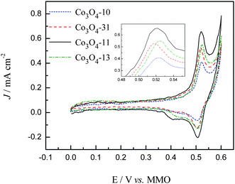 |
| | Fig. 5 CV curves in 1.0 M KOH at a sweep rate of 50 mV S−1. | |
Although the general features of the voltammetric curves are somewhat similar, it is evident that the morphology of the cobalt oxides has a significant influence on the exposed numbers of Co3+ species. From the integrated area of the Co3+ oxidation peaks shown in Fig. 5, it can be evaluated that the electrochemical active surface area (EASA) of cobalt oxides in the carbon support is in the sequence of Co3O4-11 > Co3O4-13 > Co3O4-31 > Co3O4-10. For the sake of comparison, the CV curves between the range of 0.48 and 0.56 V are enlarged in the inset of Fig. 5 and the peak values are summarized in Table 1. As compared with the Co3O4-10 electrode, the slightly negative shift of the peak position was observed for the Co3O4-31 and Co3O4-11 electrodes which indicated the increased electron density of the Co3+ species for the Co3O4-31 and Co3O4-11 electrodes. While the decreased electron density of the Co3+ species was observed for the Co3O4-13 electrode due to the positive shift of the peak position.
| Electrode |
E
p (Co3+)/mV |
J
−50, −600 mV/mA cm−2 |
Tafel slope/mV dec−1 |
| Co3O4-10 |
52.3 |
0.168, 2.39 |
104/44 |
| Co3O4-31 |
51.7 |
0.210, 2.88 |
100/53 |
| Co3O4-11 |
52.0 |
0.239, 3.54 |
78/48 |
| Co3O4-13 |
52.5 |
0.124, 3.03 |
86/49 |
Polarization curves for the ORR of the carbon supported cobalt oxide catalysts were recorded in 1.0 M KOH solution saturated with pure oxygen. The LSV curves are shown in Fig. 6 along with the Pd/C catalyst for comparison. As can be seen in Fig. 6, the ORR on the carbon supported cobalt oxide catalysts is diffusion controlled when the potential is less than −0.2 V and is under mixed diffusion kinetics control in the potential region from −0.2 to −0.05 V. The potential ranging from −0.05 to 0 V falls in the kinetics controlled region.10 It can be seen from the figure that the Co3O4-13 catalyst shows the lower catalytic activity, while the Co3O4-31 and Co3O4-11 catalysts show higher catalytic activity for ORR as compared with the Co3O4-10 catalyst at the kinetics controlled region. At the diffusion controlled region, the value of the ORR current density for the four catalysts is in the sequence of Co3O4-11 > Co3O4-13 > Co3O4-31 > Co3O4-10, which is consistent with the EASA shown in Fig. 5. The specific activity of the cobalt oxide electrodes was calculated at −0.05 and −0.60 V with the data shown in Table 1. It can be seen from Fig. 6 that the Co3O4-11 catalyst shows the highest catalytic activity among the four electrodes. In particular, it is noticed that the current density of the Co3O4-11 catalyst is higher than the carbon supported noble Pd catalyst at the low potential region (−0.12 to −0.6 V). The high catalytic activity of the Co3O4-11 electrode at both the kinetic and diffusion controlled regions shown in Table 1 can be explained by the following two aspects: (I) the high electron density of the surface Co3+ species on the Co3O4-11 electrode, which favors the ORR in alkaline media. It is reported16 that the surface Co3+ cations on the cobalt oxide electrode can produce surface electronic states by the Jahn–Teller effect in alkaline media. These surface states can capture electrons from the bulk oxide to form excited cationic states [Co3+ + e], which can be envisaged as the active sites for the alkaline ORR. (II) The Co3O4 nano-rods in the Co3O4-11 catalyst give the highest exposed Co3+ sites on the carbon support, which contributes to the high current density.16,30,31
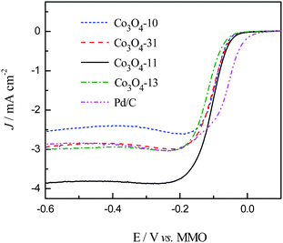 |
| | Fig. 6 Linear sweep (5 mV s−1) recorded in 1.0 M KOH solution saturated with oxygen at a rotating rate of 2400 rpm. | |
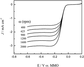
The dynamics of oxygen reduction on cobalt oxide catalysts were then examined by rotating disk voltammetry. Fig. 7 shows a series of rotating disk voltammograms of oxygen reduction at the Co3O4-11 catalyst at different rotation rates in 1.0 M KOH saturated with oxygen. The RDE data were analyzed using the Koutecky–Levich equation:
| |  | (7) |
| | | B = 0.62nFCoD2/3oυ−1/6 | (8) |
where
J is the measured current density,
JK and
JL are the kinetic and diffusion limiting current density, respectively,
ω is the
electrode rotation rate,
n is the overall number of
electron transfer,
F is the Faraday constant (96
![[thin space (1/6-em)]](https://www.rsc.org/images/entities/char_2009.gif)
485 C mol
−1),
Co is the bulk concentration of O
2 dissolved in the electrolyte,
Do is the O
2 diffusion coefficient, and
ν is the kinematic viscosity of the electrolyte.
32 Therefore, based on the Koutecky–Levich equation, a plot of the inverse of the current density
J−1versus ω−1/2 should yield a straight line with the intercept corresponding to
JK and the slopes reflecting the so-called
B factor (
eqn (8)). The number of
electron transfer in the O
2 reduction process can then be calculated from the
B factor by using the literature data of
Co = 0.93 × 10
−6 mol cm
−3,
Do = 1.30 × 10
−5 cm
2 s
−1 and
ν = 5.45 × 10
−3 cm
2 s
−1.
33Fig. 8 shows the corresponding Koutecky–Levich plots for the Co
3O
4-11
electrode. It can be seen that at the Co
3O
4-11
electrode the slopes remain approximately constant over the potential range under study (−0.05 V to −0.20 V), indicating a consistent number of
electron transfer for ORR at different
electrode potentials. Specifically, based on
eqn (7) and
(8), the number of
electron transfer (
n) in
oxygen reduction was estimated to be 4 at the potential region of −0.05 to −0.20 V. The estimation of
n for other
electrodes was also carried out in a similar manner and the same results are acquired. This result indicates that the complete 4-electron pathway for ORR was achieved on the four cobalt oxide
electrodes. We also measured the Pd/C
electrode at different
rotating disk electrode rates, from which the number of the exchanged electrons during ORR were extracted. The number of
n in
oxygen reduction was estimated to be 4 in the potential region of 0.02 to −0.05 V and −0.15 to −0.60 V, which indicates an efficient
reduction of
oxygen on the Pd/C
catalyst. However, in the potential region from −0.05 to −0.15 V, the calculated value was lower than 3.2, suggesting the incomplete
reduction of
oxygen on the Pd/C
catalyst in this region.
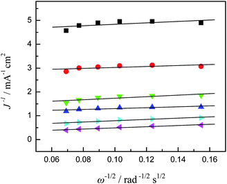 |
| | Fig. 8 Koutecky–Levich plots (from Fig. 7) at different electrode potentials, ■ −0.05 V, ● −0.06 V, ▼ −0.07 V, ▲ −0.08 V, ▶ −0.10 V, and ◀ −0.20 V. | |
The Tafel plots for ORR on the Pd/C and cobalt oxide electrodes are shown in Fig. 9. As can be observed in Fig. 9, the Tafel plot of Pd/C shows two linear regions. At low overpotentials, ca. −0.05 to 0 V, the Tafel slope was −74 mV dec−1, whereas at high overpotentials, ca. < −0.06 V, it was −155 mV dec−1. The two slopes can be explained in terms of O2 coverage: the Temkin isotherm (high coverage) at low overpotential, which indicates that the first electron transfer is the rate-determining step and the Langmuir isotherm (low coverage) at high overpotential, this is commonly interpreted in terms of a two-electron transfer reaction as the rate-determining step. These results are consistent with those from previous studies on carbon-supported Pd and bimetallic Pd-based electrodes in alkaline ORR.34,35 For the carbon supported cobalt oxide electrodes, two different linear Tafel regions are also observed for low and high overpotentials, respectively. The similar behavior observed from the Tafel plots (Table 1) of the four cobalt oxide catalysts suggests that the reaction pathway and the rate-determining step are the same for these electrodes, which is consistent with the Co-based ORR catalysts reported elsewhere.13,36 From Fig. 9, it can be observed that the intrinsic surface activities of the carbon supported cobalt oxide catalysts are lower than the Pd/C catalyst in the potential region of 0 to −0.12 V. However, in the potential region of −0.12 to −0.20 V, the incomplete reduction of oxygen with the Pd/C catalyst lowers the ORR current density, while the higher current density with the Co3O4-11 catalyst suggests that the Co3O4-11 catalyst has a higher catalytic activity than the Pd/C catalyst does.
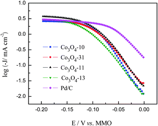 |
| | Fig. 9 Tafel plots for ORR on Pd/C and cobalt oxide electrodes. | |
The present results show that altering the morphology of the cobalt oxides does not change the reaction mechanism of the ORR in alkaline media while it can modify the catalytic activity of the Co3O4 catalysts by tailoring the number and activity of surface exposed Co3+ species. These results suggest that the Co3O4 with the nano-rod structures are promising non-precious electrocatalysts for ORR in alkaline media. For certain, the catalytic activity of the cobalt oxide catalysts may be further optimized by the composition and surface engineering of the nanocomposite catalysts.
4. Concluding remarks
In this work, the carbon-supported Co3O4 nanoparticles with the rod and spherical structures were prepared in the mixed water and DMF solvent and characterized with TGA, XPS, FTIR and TEM measurements. The catalytic activities of the prepared catalysts for the ORR in an alkaline medium were investigated. The studies indicated that the ORR catalytic activity of the prepared catalysts is sensitive to the number and activity of surface exposed Co3+ ions that can be tailored by the morphology of cobalt oxides. The Co3O4 nano-rod catalyst prepared in the water to DMF ratio of 1![[thin space (1/6-em)]](https://www.rsc.org/images/entities/char_2009.gif) :
:![[thin space (1/6-em)]](https://www.rsc.org/images/entities/char_2009.gif) 1 (∼12 nm in length and ∼5.1 nm in diameter) shows the highest catalytic activity for the ORR. It is found that this non-precious catalyst exhibits a higher activity than the noble Pd catalyst does at the low potential region. These results suggest that the Co3O4 with the nano-rod structures are promising non-precious electrocatalysts for ORR in direct AEM fuel cells. The optimization of this class of electrocatalyst will be pursued in the future work.
1 (∼12 nm in length and ∼5.1 nm in diameter) shows the highest catalytic activity for the ORR. It is found that this non-precious catalyst exhibits a higher activity than the noble Pd catalyst does at the low potential region. These results suggest that the Co3O4 with the nano-rod structures are promising non-precious electrocatalysts for ORR in direct AEM fuel cells. The optimization of this class of electrocatalyst will be pursued in the future work.
Acknowledgements
The work described in this paper was fully supported by a grant from the Research Grants Council of the Hong Kong Special Administrative Region, China (project no. 623010).
Notes and references
- V. R. Stamenkovic, B. Fowler, B. S. Mun, G. Wang, P. N. Ross, C. A. Lucas and N. M. Markovic, Science, 2007, 315, 493–497 CrossRef CAS.
- Z. Xie, X. Zhao, M. Adachi, Z. Shi, T. Mashio, A. Ohma, K. Shinohara, S. Holdcroft and T. Navessin, Energy Environ. Sci., 2008, 1, 184–193 CAS.
- E. F. Abo Zeid, D. S. Kim, H. S. Lee and Y. T. Kim, J. Appl. Electrochem., 2010, 40, 1917–1923 CrossRef CAS.
- A. Sarapuu, M. Nurmik, H. Mandar, A. Rosental, T. Laaksonen, K. Kontturi, D. J. Schiffrin and K. Tammeveski, J. Electroanal. Chem., 2008, 612, 78–86 CrossRef CAS.
- E. Yeager, Electrochim. Acta, 1984, 29, 1527–1537 CrossRef CAS.
- J. B. Xu, T. S. Zhao, W. W. Yang and S. Y. Shen, Int. J. Hydrogen Energy, 2010, 35, 8699–8706 CrossRef CAS.
- Y. S. Li, T. S. Zhao and Z. X. Liang, J. Power Sources, 2009, 187, 387–392 CrossRef CAS.
- C. Bianchini and P. K. Shen, Chem. Rev., 2009, 109, 4183–4206 CrossRef CAS.
- S. Song, Y. Wang, P. Tsiakaras and P. K. Shen, Appl. Catal., B, 2008, 78, 381–387 CrossRef CAS.
- J. B. Xu, T. S. Zhao, Y. S. Li and W. W. Yang, Int. J. Hydrogen Energy, 2010, 35, 9693–9700 CrossRef CAS.
- J. S. Spendelow and A. Wieckowski, Phys. Chem. Chem. Phys., 2007, 9, 2654–2675 RSC.
- Z. X. Liang, T. S. Zhao, J. B. Xu and L. D. Zhu, Electrochim. Acta, 2009, 54, 2203–2208 CrossRef CAS.
- M. Hamdani, R. N. Singh and P. Chartier, Int. J. Electrochem. Sci., 2010, 5, 556–577 CAS.
- M. Longhi and L. Formaro, J. Electroanal. Chem., 1999, 464, 149–157 CrossRef CAS.
- A. Restovic, E. Rios, S. Barbato, J. Ortiz and J. L. Gautier, J. Electroanal. Chem., 2002, 522, 141–151 CrossRef CAS.
-
Comprehensive Chemical Kinetics, ed. R. G. Compton, Elsevier, 1987 Search PubMed.
- G. Spinolo, S. Ardizzone and S. Trasatti, J. Electroanal. Chem., 1997, 423, 49–57 CrossRef CAS.
- A. M. Cao, J. S. Hu, H. P. Liang, W. G. Song, L. J. Wan, X. L. He, X. G. Gao and S. H. Xia, J. Phys. Chem. B, 2006, 110, 15858–15863 CrossRef CAS.
- J. Feng and H. C. Zeng, Chem. Mater., 2003, 15, 2829–2835 CrossRef CAS.
- B. B. Lakshmi, C. J. Patrissi and C. R. Martin, Chem. Mater., 1997, 9, 2544–2550 CrossRef CAS.
- C. Nethravathi, S. Sen, N. Ravishankar, M. Rajamathi, C. Pietzonka and B. Harbrecht, J. Phys. Chem. B, 2005, 109, 11468–11472 CrossRef CAS.
- Y. Wang, C. M. Yang, W. Schmidt, B. Spliethoff, E. Bill and F. Schüth, Adv. Mater., 2005, 17, 53–56 CrossRef CAS.
- Z. Xu, Z. Chen, Y. Ben and J. Shen, Mater. Lett., 2009, 63, 1210–1212 CrossRef CAS.
- A. A. Athawale, V. Singh, B. R. Mehta and K. Navinkiran, J. Alloys Compd., 2010, 492, 331–338 CrossRef CAS.
- S. Y. Shen, T. S. Zhao, J. B. Xu and Y. S. Li, J. Power Sources, 2010, 195, 1001–1006 CrossRef CAS.
- Z. P. Xu and H. C. Zeng, J. Mater. Chem., 1998, 8, 2499–2506 RSC.
- L. Fu, Z. Liu, Y. Liu, B. Han, P. Hu, L. Cao and D. Zhu, Adv. Mater., 2005, 17, 217–221 CrossRef CAS.
- B. Ernst, S. Libs, P. Chaumette and A. Kiennemann, Appl. Catal., A, 1999, 186, 145–168 CrossRef CAS.
- R. Vijaya Kumar, Y. Diamant and A. Gedanken, Chem. Mater., 2000, 12, 2301–2305 CrossRef.
- F. H. B. Lima, M. L. Calegaro and E. A. Ticianelli, J. Electroanal. Chem., 2006, 590, 152–160 CrossRef CAS.
- F. Svegl, B. Orel, I. Grabec-Svegl and V. Kaucic, Electrochim. Acta, 2000, 45, 4359–4371 CrossRef CAS.
- W. Chen, D. Ny and S. Chen, J. Power Sources, 2010, 195, 412–418 CrossRef CAS.
- R. E. Davis, G. L. Horvath and C. W. Tobias, Electrochim. Acta, 1967, 12, 287–297 CrossRef CAS.
- L. Jiang, A. Hsu, D. Chu and R. Chen, J. Electrochem. Soc., 2009, 156, B370–B376 CrossRef CAS.
- L. Jiang, A. Hsu, D. Chu and R. Chen, Electrochim. Acta, 2010, 55, 4506–4511 CrossRef CAS.
- M. De Koninck and B. Marsan, Electrochim. Acta, 2008, 53, 7012–7021 CrossRef CAS.
|
| This journal is © The Royal Society of Chemistry 2012 |
Click here to see how this site uses Cookies. View our privacy policy here. ![[thin space (1/6-em)]](https://www.rsc.org/images/entities/char_2009.gif) :
:![[thin space (1/6-em)]](https://www.rsc.org/images/entities/char_2009.gif) 1 exhibits a higher current density than a much more expensive palladium-based catalyst does at the low potential region.
1 exhibits a higher current density than a much more expensive palladium-based catalyst does at the low potential region.![[thin space (1/6-em)]](https://www.rsc.org/images/entities/char_2009.gif) :
:![[thin space (1/6-em)]](https://www.rsc.org/images/entities/char_2009.gif) 1 exhibits a higher limiting current density than a much more expensive Pd/C catalyst does.
1 exhibits a higher limiting current density than a much more expensive Pd/C catalyst does.
![[thin space (1/6-em)]](https://www.rsc.org/images/entities/char_2009.gif) :
:![[thin space (1/6-em)]](https://www.rsc.org/images/entities/char_2009.gif) 1 exhibits the highest catalytic activity for the ORR among all the catalyst samples prepared under different conditions. We further show that this particular Co3O4 electrocatalyst exhibits a higher catalytic activity for the ORR than a much more expensive carbon supported noble palladium catalyst does.
1 exhibits the highest catalytic activity for the ORR among all the catalyst samples prepared under different conditions. We further show that this particular Co3O4 electrocatalyst exhibits a higher catalytic activity for the ORR than a much more expensive carbon supported noble palladium catalyst does.![[thin space (1/6-em)]](https://www.rsc.org/images/entities/char_2009.gif) :
:![[thin space (1/6-em)]](https://www.rsc.org/images/entities/char_2009.gif) 0, 3
0, 3![[thin space (1/6-em)]](https://www.rsc.org/images/entities/char_2009.gif) :
:![[thin space (1/6-em)]](https://www.rsc.org/images/entities/char_2009.gif) 1, 1
1, 1![[thin space (1/6-em)]](https://www.rsc.org/images/entities/char_2009.gif) :
:![[thin space (1/6-em)]](https://www.rsc.org/images/entities/char_2009.gif) 1 and 1
1 and 1![[thin space (1/6-em)]](https://www.rsc.org/images/entities/char_2009.gif) :
:![[thin space (1/6-em)]](https://www.rsc.org/images/entities/char_2009.gif) 3, respectively; the prepared precursor solution (200 ml in a beaker) was mixed with carbon powder under stirring, after a homogeneous solution was obtained, 30 mL of ammonia solution was added, respectively; after stirring at room temperature, the products were aged for 24 h and the resulting precipitates were centrifuged, followed by washing with distilled water and ethanol, and dried at 60 °C in an oven. The prepared cobalt hydroxides with the metal loading of 20 wt% were denoted by Co(OH)2-10, Co(OH)2-31, Co(OH)2-11 and Co(OH)2-13 with the postfix number for the water to DMF ratio in mixed solvent, respectively. The carbon supported cobalt oxides were obtained by further heat treatment of the cobalt hydroxides at 330 °C for 2 h with the resulted samples denoted by Co3O4-10, Co3O4-31, Co3O4-11 and Co3O4-13, respectively. For comparison, the carbon supported palladium catalyst with a metal loading of 20 wt% was prepared with a method reported elsewhere.25
3, respectively; the prepared precursor solution (200 ml in a beaker) was mixed with carbon powder under stirring, after a homogeneous solution was obtained, 30 mL of ammonia solution was added, respectively; after stirring at room temperature, the products were aged for 24 h and the resulting precipitates were centrifuged, followed by washing with distilled water and ethanol, and dried at 60 °C in an oven. The prepared cobalt hydroxides with the metal loading of 20 wt% were denoted by Co(OH)2-10, Co(OH)2-31, Co(OH)2-11 and Co(OH)2-13 with the postfix number for the water to DMF ratio in mixed solvent, respectively. The carbon supported cobalt oxides were obtained by further heat treatment of the cobalt hydroxides at 330 °C for 2 h with the resulted samples denoted by Co3O4-10, Co3O4-31, Co3O4-11 and Co3O4-13, respectively. For comparison, the carbon supported palladium catalyst with a metal loading of 20 wt% was prepared with a method reported elsewhere.25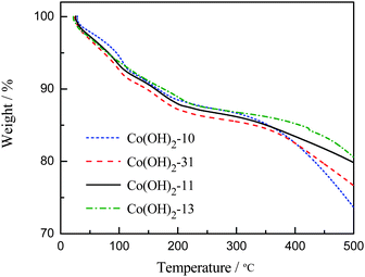
![[thin space (1/6-em)]](https://www.rsc.org/images/entities/char_2009.gif) :
:![[thin space (1/6-em)]](https://www.rsc.org/images/entities/char_2009.gif) 1 in the mixed solvent, the even more shortened Co3O4 nano-rods were achieved in the Co3O4-11 sample with ∼12 nm in length and ∼5.1 nm in diameter. A high-resolution TEM (HRTEM) image is also presented in the inset of Fig. 4c. From this HRTEM image, it can be observed that the crystalline nanorod is formed on the carbon powder during the nucleation and growth process. The TEM image of the Co3O4-13 sample is shown in Fig. 4d. It can be seen that the Co3O4 particles prepared in the water to DMF ratio of 1 to 3 are roughly spherical in shape, the mean particle size of the Co3O4 particles is 10.5 nm. This result indicates that the morphology control of Co3O4 nanostructures was achieved in the developed mixed solvent of water and DMF. It is believed that DMF plays three distinct roles in the mixed solvent system: solvent, pH adjustor and ligand. The pH can be adjusted in the mixed solvent because the anion solvating ability is slower in DMF than that of water, and DMF coordinated Co2+ ions may control the growth direction of crystals serving as structure-directing reagent. The same result was observed in Kumar's work.29 It can be observed from Fig. 4 that the incidental aggregation accrued for the entire carbon supported cobalt oxide samples. This phenomenon may result from the heat treatment process, which was absent in the cobalt hydroxide samples.
1 in the mixed solvent, the even more shortened Co3O4 nano-rods were achieved in the Co3O4-11 sample with ∼12 nm in length and ∼5.1 nm in diameter. A high-resolution TEM (HRTEM) image is also presented in the inset of Fig. 4c. From this HRTEM image, it can be observed that the crystalline nanorod is formed on the carbon powder during the nucleation and growth process. The TEM image of the Co3O4-13 sample is shown in Fig. 4d. It can be seen that the Co3O4 particles prepared in the water to DMF ratio of 1 to 3 are roughly spherical in shape, the mean particle size of the Co3O4 particles is 10.5 nm. This result indicates that the morphology control of Co3O4 nanostructures was achieved in the developed mixed solvent of water and DMF. It is believed that DMF plays three distinct roles in the mixed solvent system: solvent, pH adjustor and ligand. The pH can be adjusted in the mixed solvent because the anion solvating ability is slower in DMF than that of water, and DMF coordinated Co2+ ions may control the growth direction of crystals serving as structure-directing reagent. The same result was observed in Kumar's work.29 It can be observed from Fig. 4 that the incidental aggregation accrued for the entire carbon supported cobalt oxide samples. This phenomenon may result from the heat treatment process, which was absent in the cobalt hydroxide samples.


![[thin space (1/6-em)]](https://www.rsc.org/images/entities/char_2009.gif) 485 C mol−1), Co is the bulk concentration of O2 dissolved in the electrolyte, Do is the O2 diffusion coefficient, and ν is the kinematic viscosity of the electrolyte.32 Therefore, based on the Koutecky–Levich equation, a plot of the inverse of the current density J−1versus ω−1/2 should yield a straight line with the intercept corresponding to JK and the slopes reflecting the so-called B factor (eqn (8)). The number of electron transfer in the O2 reduction process can then be calculated from the B factor by using the literature data of Co = 0.93 × 10⁻⁶ mol cm−3, Do = 1.30 × 10⁻⁵ cm2 s−1 and ν = 5.45 × 10⁻³ cm2 s−1.33Fig. 8 shows the corresponding Koutecky–Levich plots for the Co3O4-11 electrode. It can be seen that at the Co3O4-11 electrode the slopes remain approximately constant over the potential range under study (−0.05 V to −0.20 V), indicating a consistent number of electron transfer for ORR at different electrode potentials. Specifically, based on eqn (7) and (8), the number of electron transfer (n) in oxygen reduction was estimated to be 4 at the potential region of −0.05 to −0.20 V. The estimation of n for other electrodes was also carried out in a similar manner and the same results are acquired. This result indicates that the complete 4-electron pathway for ORR was achieved on the four cobalt oxide electrodes. We also measured the Pd/C electrode at different rotating disk electrode rates, from which the number of the exchanged electrons during ORR were extracted. The number of n in oxygen reduction was estimated to be 4 in the potential region of 0.02 to −0.05 V and −0.15 to −0.60 V, which indicates an efficient reduction of oxygen on the Pd/C catalyst. However, in the potential region from −0.05 to −0.15 V, the calculated value was lower than 3.2, suggesting the incomplete reduction of oxygen on the Pd/C catalyst in this region.
485 C mol−1), Co is the bulk concentration of O2 dissolved in the electrolyte, Do is the O2 diffusion coefficient, and ν is the kinematic viscosity of the electrolyte.32 Therefore, based on the Koutecky–Levich equation, a plot of the inverse of the current density J−1versus ω−1/2 should yield a straight line with the intercept corresponding to JK and the slopes reflecting the so-called B factor (eqn (8)). The number of electron transfer in the O2 reduction process can then be calculated from the B factor by using the literature data of Co = 0.93 × 10⁻⁶ mol cm−3, Do = 1.30 × 10⁻⁵ cm2 s−1 and ν = 5.45 × 10⁻³ cm2 s−1.33Fig. 8 shows the corresponding Koutecky–Levich plots for the Co3O4-11 electrode. It can be seen that at the Co3O4-11 electrode the slopes remain approximately constant over the potential range under study (−0.05 V to −0.20 V), indicating a consistent number of electron transfer for ORR at different electrode potentials. Specifically, based on eqn (7) and (8), the number of electron transfer (n) in oxygen reduction was estimated to be 4 at the potential region of −0.05 to −0.20 V. The estimation of n for other electrodes was also carried out in a similar manner and the same results are acquired. This result indicates that the complete 4-electron pathway for ORR was achieved on the four cobalt oxide electrodes. We also measured the Pd/C electrode at different rotating disk electrode rates, from which the number of the exchanged electrons during ORR were extracted. The number of n in oxygen reduction was estimated to be 4 in the potential region of 0.02 to −0.05 V and −0.15 to −0.60 V, which indicates an efficient reduction of oxygen on the Pd/C catalyst. However, in the potential region from −0.05 to −0.15 V, the calculated value was lower than 3.2, suggesting the incomplete reduction of oxygen on the Pd/C catalyst in this region.


![[thin space (1/6-em)]](https://www.rsc.org/images/entities/char_2009.gif) :
:![[thin space (1/6-em)]](https://www.rsc.org/images/entities/char_2009.gif) 1 (∼12 nm in length and ∼5.1 nm in diameter) shows the highest catalytic activity for the ORR. It is found that this non-precious catalyst exhibits a higher activity than the noble Pd catalyst does at the low potential region. These results suggest that the Co3O4 with the nano-rod structures are promising non-precious electrocatalysts for ORR in direct AEM fuel cells. The optimization of this class of electrocatalyst will be pursued in the future work.
1 (∼12 nm in length and ∼5.1 nm in diameter) shows the highest catalytic activity for the ORR. It is found that this non-precious catalyst exhibits a higher activity than the noble Pd catalyst does at the low potential region. These results suggest that the Co3O4 with the nano-rod structures are promising non-precious electrocatalysts for ORR in direct AEM fuel cells. The optimization of this class of electrocatalyst will be pursued in the future work.
