Oxidative desulfurization of light gas oil using zinc catalysts prepared via different techniques
M.
Riad
* and
S.
Mikhail
Egyptian Petroleum Research Institute, Nasr City, Hai Al-Zehour, PO Box 11727, Cairo, Egypt. E-mail: mary_riad@hotmail.com; maryriad2006@yahoo.com
First published on 10th April 2012
Abstract
Zn-incorporated hydroxyapatite catalysts were prepared by two different techniques: wet impregnation and ion exchange with different zinc loadings. The prepared catalysts were characterized by different techniques. The catalytic activity of zinc catalysts was investigated towards oxidative desulfurization of light gas oil with a total sulfur content of 1281.8 ppm. The reaction was performed in a batch system and in the presence of hydrogen peroxide as oxidant. The influence of various operating parameters including reaction temperature, oxidation time and oxidant to sulfur molar ratio on the sulfur removal of light gas oil was investigated. The results revealed that an increase in the reaction temperature enhanced the sulfur removal. The maximum observed sulfur removal reached 89.7% using zinc catalysts prepared via the ion exchange technique. The formed active phase (parascholozite) and BET surface area could explain this activity.
1 Introduction
Hydrodesulfurization (HDS) is an important part in clean fuel technology to meet the new emission control standard. HDS technique must be operated at high temperature and pressure and consumes large amounts of hydrogen. Also, some specific sulfur-containing organic molecules, such as dibenzothiophene (DBT) and derivatives are however refractory to normal hydro-treating processes. Alternative technologies are being developed for ultra low sulfur fuels1 such as: catalytic oxidative desulfurization (ODS), selective adsorption, bio-desulfurization and oxidation/extraction.1–7 Oxidative desulfurization (ODS) process is the most promising alternative to HDS for the removal of benzothiophene derivatives. In this process, benzothiophene, dibenzothiophene, and their corresponding alkyl derivatives can be oxidized into the corresponding sulfoxides and ssulfones Basically, oxidative desulfurization (ODS) is a two-stage process of oxidation using an oxidant like H2O2 and basic catalysts, the second stage is the removal of sulfones by liquid extraction or adsorption.Lanju et al.,8 tested the ODS of simulated gasoline containing model sulfur compounds in the presence of: hydrogen peroxide & formic acid as an oxidative system and cerium oxide-loaded molecular sieve catalyst. The results indicate the phase transfer catalyst improved the removal of C4H4S and 3-MC4H4S (78.4 and 82.3% respectively) in the oxidation reaction system. Yan et al.,9 synthesized a series of mesoporous phosphotungstic acid/TiO2 (HPW/TiO2) which are used as catalysts for ODS of model fuel in the presence of H2O2 as oxidant. Kumagai et al.,10 studied ODS of a Mexican diesel fuel on Mo and/or V oxides supported on alumina using tert-butyl hydro-peroxide (TBHP) or H2O2 as an oxidant to obtain low sulfur diesel fuel. The catalytic results show that V-Mo based catalysts are more active during several ODS cycles using TBHP. Song et al.,11,12 have prepared Au/Ti-HMS by NH3 deposition–precipitation (NH3 DP), urea deposition–precipitation (Urea DP) and an in situ-reduction method using NaBH4 as reducing agent respectively and studied their performance towards ODS of n-octane containing BT, DBT and 4,6-DMDBT as model compounds (using in situ generated H2O2 from H2 and O2).
Haw et al.,13 studied ODS process of diesel fuel utilizing hydrogen peroxide and functionalized-activated carbon in a biphasic diesel–acetonitrile system, under the best operating conditions: temperature 50 °C, atmospheric pressure, 0.5 g activated carbon, 3 mol ratio of hydrogen peroxide to sulfur, 2 mol ratio of acetic acid to sulfur, 3 oxidation cycles with 1 h for each cycle using acetonitrile as an extraction solvent, the sulfur content in diesel was reduced from 2189 ppm to 190 ppm with 91.3% of total sulfur removal.
Toteva's14 work showed that the extraction processes after the oxidation lead to the loss of a significant amount of aromatic hydrocarbons. It is well known that the extraction of solvent in the ODS process may result in the separation problem between oil and solvent phase causing a loss of oil and further limitations for industrial applications, so it is suggested that for an ODS process with a solid catalyst, the use of solvent should be avoided.
Ma et al.,15 have investigated the ODS of a model jet fuel and a real jet fuel with molecular oxygen and an Fe(III) salt at 25 °C. The reaction products were adsorbed on activated carbon which has a high adsorptive affinity for the sulfones due to the higher polarity of the former. The remarkable advantage of the developed ODS can run in the presence of oxygen without using aqueous solvent and thus without involving the biphasic oil–aqueous solution system.
Jia et al.16 investigated the ODS process for model fuel which was performed with hydrogen peroxide and 14 wt% MoO3/γ-Al2O3 as a catalyst and an adsorbent in a solvent free system.
Hydroxyapatite (Hap) has two channels and has both acidic and basic sites in its crystal lattice, and so it is expected to perform as both acid and base catalyst. It is widely used as adsorbent,17,18 support19 and catalysts in oxidation20 and dehydrogenation reactions.21 Hap shows a high capacity for the substitutions of Ca2+ and PO43− ions by other cations and anions. The partially substituted hydroxyapatite by Co2+![[thin space (1/6-em)]](https://www.rsc.org/images/entities/char_2009.gif) 22 and Zn2+23 were investigated as catalysts for the oxidative dehydrogenation of propane and the Michael reactions. Limited work has been reported on the studies of hydroxyapatite as a catalyst in ODS process.
22 and Zn2+23 were investigated as catalysts for the oxidative dehydrogenation of propane and the Michael reactions. Limited work has been reported on the studies of hydroxyapatite as a catalyst in ODS process.
This work investigates the preparation of hydroxyapatite and Zn-hydroxyapatite catalysts by impregnation and ion exchange techniques. Besides, the performance of these catalysts was studied towards the catalytic oxidative desulfurization of light gas oil in one oxidation cycle for one hour and in a solvent free system, so the separation between oil phase and catalyst can be carried out easily by centrifugation, and the loss of oil phase can be reduced.
2 Experimental
2.1. Preparation of the support material
Hydroxyapatite (Hap) was prepared by a co-precipitation technique according to Narasaraju et al.,24 and Tkalcec et al.,25 methods.| 6(NH4)2HPO4 + 10Ca(NO3)2 + 8NH4OH → Ca10(PO4)6(OH)2 (Hap) + 20NH4NO3 + 6H2O |
2.2. Preparation of Zn-hydroxyapatite catalysts
2.3. Characterization
X-ray Diffraction (XRD) was carried out on an XD-D1 X-ray diffraction Schimadzu, Cu-Kα radiation was the light source. Two theta angles ranged from 4 to 80° with a speed of 2° min−1, the formed phases of the calcined materials were detected. The crystallite size was calculated from X-ray line broadening using the Scherrer equation.26 The values of the lattice parameter were determined based on the XRD data collected under the following conditions: 2θ range, 20–508; scan rate, 0.58 min−1; sampling width, 0.0068; internal standard, Si (silicon powder, 99.99%, Rare Metallic) using the Rietveld full profile method and Koalarie computer software.27Fourier Transformer Infra Red (FT-IR) spectra were run on Perkin Elmer FT-IR apparatus working in the range of 4000–400 cm−1 to identify the hydroxyl and functional groups contained in the calcined materials.
Differential Scanning Calorimetry Analysis (DSC) was carried out using the Differential Thermal Analyzer, Perkin Elmer apparatus, to study the phases formed upon thermal treatment and the enthalpy of prepared catalysts.
The Ca/P ratio and the metal loading were determined by X-ray fluorescence (XRF) using Rigaku Sequential Spectrometer (RI × 3100) equipment with Rh source.
N2 adsorption measurements:28 The surface area, pore volume and pore size distribution of the calcined catalysts were determined using a micromeritics adsorption equipment (Model ASAP2000) which was equipped with a micro-pore analysis program using N2 (Bixiou Gas Ltd., Shanghai, China) as the analysis gas. Prior to analysis, each catalyst was evacuated at 573 K at a vacuum of 0.54 kPa for 10 h. The surface area was evaluated using BET method and the Dubinin–Astakhov program was used in evaluating the micro-pore surface areas, while the Horvath–Kawazoe equation was used to estimate the median pore sizes of the studied materials.
2.4. Catalytic reaction
The physical characteristics of light gas oil supplied from the Cairo Refining Petroleum Company are included in Table 1. In each experimental run, about 250 ml of light gas oil with a total sulfur content of 1281.8 ppm was introduced into a three-necked glass reactor equipped with a condenser and a thermometer. The reactor was placed in a constant-temperature water bath with stirring. An appropriate amount of hydrogen peroxide (as oxidant) and the calcined catalysts were then added to the reactor The mixture was stirred continuously and heated to the desired reaction temperature. Then the mixture was settled to attain phase separation and the separated gas oil was adsorbed on activated bentonite-clay material at 25 °C. The H2O2 concentration was determined by iodometric titration6 and the sulfur concentration was measured by X-ray fluorescence analysis on a LAB-X3000 apparatus.| Characteristics | Light gas oil |
|---|---|
| Color D-1500 | 0.5 |
| Total sulfur (ppm) D-5453 | 1281.8 |
| Distillation characteristics | |
| Initial boiling point (°C IBP) D-2887 | 185 |
| 50% Recovery D-2887 | 270 |
| 90% Recovery D-2887 | 310 |
| End point D-2887 | 330 |
| Specific gravity at 60 °F D-4052 | 0.8530 |
| Pour point D-97 | 12 |
| Cloud point D-2500 | 15 |
| Flash point (°C) D-93 | 67 |
3. Results and discussion
3.1. Chemical analysis
The chemical compositions and Ca/P ratio of the studied materials are included in Table 2. The support hydroxyapatite material contains Ca (wt%):37.4 and P (wt%):17.92 with Ca/P ratio: 1.62 which are lower than the theoretical value of a stoichiometric hydroxyapatite (Ca/P = 1.67) and confirms its Ca-deficient feature. For the impregnated samples, the zinc content is nearly the same as that introduced in the solutions (10 and 20 wt%). Meanwhile, it decreases upon substitution of Ca by Zn species, in agreement with Faria et al.,29 who observed that Zn2+ cation incorporation was limited by a value of 6–7% of metal incorporated and it is possibly caused by a diffusion limit. Miyaji et al.,30 estimated also a limit of 15 mol% for Zn substitution in the Hap lattice. Also, Ca/P ratio is decreased with the increase in the exchanged zinc ions suggesting Ca2+ substitution by Zn2+ in the lattice of Hap.
| Catalyst | Ca (wt%) | P (wt%) | Zn (wt%) | Ca/P ratio |
|---|---|---|---|---|
| Hap | 37.40 | 17.92 | 0.0 | 1.62 |
| ZnHapIm1 | 37.40 | 17.92 | 9.71 | 1.62 |
| ZnHapIm2 | 37.40 | 17.92 | 19.57 | 1.62 |
| ZnHapIon1 | 34.78 | 17.35 | 3.40 | 1.55 |
| ZnHapIon2 | 31.10 | 17.89 | 5.60 | 1.35 |
3.2. Catalysts characterization

The impregnation of zinc on Ca-Hap and calcination treatment at 350 °C does not visibly modify the structure of the support, the two patterns are very similar to each other indicating that the impregnation step occurs without observable alteration in the framework lattice and losses in the crystallinity. Additional diffraction lines are observed at 2θ = 32.0, 37.2, 49.5° (Fig. 1d) when zinc species are present in high amounts, which are assigned to the ZnO phase. These additional diffraction lines cannot be found in the solids containing 10 wt% of zinc, in agreement with Faria et al.,29 who prepared Zn-based Hap catalysts by the deposition method, Singh et al.,31 and Wei et al.,32 who prepared Sr and V loaded Hap by the impregnation method respectively and found that the oxide species started to appear in the XRD pattern at up to 15% metal loading. Also, Aellach et al.33 discussed this result on a better dispersion of metal ions in the impregnation process which was caused by the presence of cationic vacancies in a higher amount at the surface of the Ca-deficient hydroxyapatite. Such ionic species are likely isolated, and thus do not contribute much to the formation of metal oxide at the stage of the calcination treatment. The pattern for ZnHapIon1,2 catalysts reveals a widening and a decreasing in the intensity of the major diffraction peaks of Hap (Fig. 1e and f), which indicated that the zinc substitution causes a decrease in the crystallinity and restrains the growth of Hap particles, in accordance with Wakamura et al., proposal34 that the divalent ions difficult to obtain in high crystallinity, cause lattice strain and greatly inhibit hydroxyapatite crystallization. Besides, the results of Anmin et al.,35 who prepared nano-crystals of titanium-substituted hydroxyapatite by the hydrothermal method and found that the intensity of hydroxyapatite diffraction peaks is weakened and half height width of major diffraction peaks is widened upon increasing the titanium content, this indicated a low crystallinity of the Ti-Hap catalyst compared to the pure Hap. On the other hand, parascholzite phase CaZn2(PO4)2·2H2O (formed upon the substitution of Ca by Zn species) appeared in the ZnHapIon2 catalyst at 2θ = 10, 12.5, 20.0, 33.5, 35.2, 38.2, 40.3, 45.1 and 49.5° (ASTM 76-0725), in agreement with the results of Mujaji et al.,29 who reported that the formation of Zn substituted hydroxyapatite by the precipitation technique and the formation of the parascholzite phase started to form at Zn fractions up to 18 wt%.
| Crystallite size (nm) | c/nm | a = b/nm | Catalysts |
|---|---|---|---|
| 49.0 | 0.6881 | 0.9423 | Hap |
| 41.5 | 0.6881 | 0.9423 | ZnHapIm1 |
| 38.7 | 0.6880 | 0.9423 | ZnHapIm2 |
| 23.0 | 0.6881 | 0.9421 | ZnHapIon1 |
| 14.0 | 0.6879 | 0.9418 | ZnHapIon2 |
Meanwhile, for ZnHapIon1 catalyst the lattice parameter a monotonously decreases while c nearly keeps its value. Meanwhile, the lattice parameters a, b and c decrease with the increase in the Zn content. This suggests that: with the increase in Zn substitution, the lattice disorder associated in the Hap lattice increases too. It is well known, the divalent ions smaller than Ca2+, such as Mg2+, Zn2+ and Mn2+ have an inhibitory effect, and this substitution of the smaller sized ion is difficult to obtain with high crystallinity and gives rise to lattice strain which inhibits hydroxyapatite,24,25 in agreement with the results of Jun et al.,39 and Boucetta et al.,40 who prepared Cr and Ni-Hap catalysts.
Therefore, the change of the lattice parameters corroborated the distortion in the crystalline structure of the original Hap after the substitution of Ca2+ for Zn2+ ions and demonstrated that Zn was structurally incorporated in Ca-Hap and does not cover the surface of the crystal.
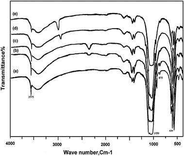 | ||
| Fig. 2 FT-IR spectrum for: (a) Hap, (b) ZnHapIm1, (c) ZnHapIm2, (d) ZnHapIon1, (e) ZnHapIon2. | ||
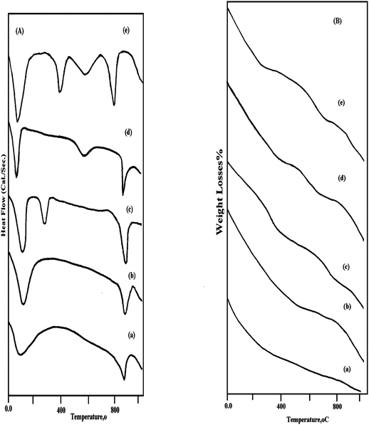 | ||
| Fig. 3 (A) Differential scanning calorimetery profile and (B) Thermogravimetric analysis for the prepared: (a) Hap, (b) ZnHapIm1, (c) ZnHapIm2, (d) Zn HapIon1, (e) Zn HapIon2. | ||
| Catalysts | Peaks location (°C) | Enthalpy (Cal g−1 s) | Weight loss (%) |
|---|---|---|---|
| Hap | 30–120 (endo) | 18.0 | 4.0 |
| 860–930 (endo) | 14.0 | 10.0 | |
| ZnHapIm1 | 35–125 (endo) | 27.0 | 10.0 |
| 850–930 (endo) | 19.0 | 13.0 | |
| ZnHapIm2 | 30–100 (endo) | 38.0 | 16.0 |
| 250–300 (endo) | 20.0 | 18.0 | |
| 860–920 (endo) | 23.0 | 20.0 | |
| ZnHapIon1 | 25–100 (endo) | 9.0 | 8.0 |
| 850–930 (endo) | 28.0 | 22.0 | |
| ZnHapIon2 | 30–160 (endo) | 18.0 | 11.0 |
| 220–320 (endo) | 16.0 | 6.0 | |
| 480–620 (endo) | 25.0 | 12.0 | |
| 650–820 (endo) | 40.0 | 29.0 |
The DSC profile for Hap revealed the appearance of an endothermic peak in the range of 30–120 °C which is attributed to the desorption of water adsorbed on the crystallite surface of hydroxyapatite. The second endothermic peak appeared at 860–930 °C which is related to the decomposition of the hydroxyapatite structure.47 Tkalcec et al.,25 established that non-stoichiometric hydroxyapatite prepared by the precipitation method starts to decompose at 800 °C when heated and transformed to calcium phosphate. Opre et al.,19 observed that non-stoichiometric Hap is decomposed at around 700 °C into stoichiometric Hap, calcium phosphate Ca3(PO4)2 and H2O. Tanaka et al.,48 suggested that the thermal decomposition of non-stoichiometric Hap has been proposed to result in the conversion of a portion of the original orthophosphate groups to the pyrophosphate form as,
| Ca10−x(HPO4)x (PO4)6−x(OH)2−x → Ca10−x(P2O7)x(PO4)6−2x(OH)2 (0 < x < 1) |
| Ca10−x(HPO4)x(PO4)6−x(OH)2−x → (1−x)Ca10(PO4)6(OH)2 + 3x Ca3(PO4)2 + xH2O |
For ZnHapIm1 catalyst the DSC profile in Fig. 3A shows the same behavior similar to hydroxyapatite material. With further increase in Zn loading to 20 w%, a new endothermic peak appeared at 250–320 °C which implied the formation of ZnO species. On the other hand, the heat of enthalpy for the endothermic peak appeared at 860–930 °C (Table 4) is increased with the increase in the zinc loading which reflected the more restrained hydroxyapatite structure.50
The DSC profile for ZnHapIon1 catalyst is comparable to that for the support, excepting an observed increase in the heat of enthalpy that is due to the incorporation of Zn species in the hydroxyapatite lattice, (Table 4). For ZnHapIon2 catalyst the DSC profile reveals the appearance of two endothermic peaks in addition to the surface adsorbed peak at 30–160 °C. The peak appearing at 480–660 °C, is related to the removal of lattice water, in accordance with Le Geros et al.,51,52 and Monma et al.,53 who reported that Ca-deficient hydroxyapatite incorporated water which is substituted for OH sites during the ion exchange process and called lattice water that vaporized gradually upon thermal treatment at 140–600 °C. The endothermic peak that appeared at 680–840 °C is ascribed to the transformation of hydroxyapatite to calcium phosphate which means Zn might promote this transformation process. Moreover, an exothermic peak appeared at 360–450 °C which implied the dehydroxylation of the hydroxyapatite structure and the formation of paraschlozite phase, in agreement with the FT-IR results.
It is noticed that, the weight losses due to the removal of adsorbed H2O and lattice H2O and the transformation from apatite to calcium phosphate increases with increase in the Zn fraction (Table 4 and Fig. 3B).
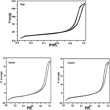 | ||
| Fig. 4 N2-adsorption–desorption isotherms for hydroxyapatite and zinc catalysts. | ||
| Catalysts | S BET (m2 g−1) | V p (cm3 g−1) | r H (Å) | Micropore surface area (m2 g−1) | Pore size distribution maxima | Consumed H2O2(%) | |
|---|---|---|---|---|---|---|---|
| Hap | 62.0 | 0.01985 | 64.0 | 7.0 | 90.0 | 7.0 | 60.0 |
| ZnHapIm1 | 56.5 | 0.01759 | 69.0 | 5.0 | 91.0 | 5.0 | 71.0 |
| ZnHap Im2 | 46.0 | 0.01710 | 77.0 | 4.0 | 93.3 | 4.0 | 78.0 |
| ZnHapIon1 | 68.0 | 0.02125 | 61.0 | 7.8 | 19.8 | 7.8 | 86.0 |
| ZnHapIon2 | 81.0 | 0.02350 | 57.0 | 9.5 | 19.8 | 9.5 | 92.0 |
All samples displayed type IV isotherms according to the IUPAC classification,54 typical of mesoporous solids. Hydroxyapatite exhibits an H1 hysteresis loop indicative of the existence of texture mesopores with cylindrical arrays of pore channels. Zinc catalysts exhibit a similar isotherm to the hydroxyapatite support suggesting that metal incorporation does not alter the support structure.55 Meanwhile, for ZnHapIon2 the amount of adsorbed gas increases abruptly at low P/P0 regions due to micro-pore filling. Subsequently, a hysteresis loop occurs at a relatively high range of 0.6 < P/P0 < 1.0 which is associated with capillary condensation taking place in mesopores.56
The data in Table 5 indicate that, the BET surface area for the Hap material is 62.0 m2 g−1 when Zn species are introduced using the impregnation method, the BET surface area of the catalyst possessed a low Zn content and is found to be similar to that of the support. This may be due to zinc species probably homogeneously distributed in the solid leading to a BET surface area similar to that of the pure support. Elazarifi et al.,57 concluded that, superficial defects and HPO42− groups that were evidenced on Ca-deficient material are necessary in order to provide a good dispersion of the metal oxide. Those superficial defects and surface HPO42− groups are grafting sites of oxides.
It should be noted that the increase in zinc loading slightly decreases the BET surface area (56.5 m2 g−1), probably because the channels of hydroxyapatite are partially packed with metal particles. This assumption is supported by the results of the micro-pore surface area (measure of the inner channel surface area of the micro-pores) which decreases slowly with the increase in Zn loading and by the slight increase in pore diameter.
Whereas, ZnHapIon1,2 catalysts show the reverse behavior, the BET surface area increases from 62.0 to 68.0 and then to 81.0 m2 g−1 upon increasing the substituted zinc cations that may be related to the decrease in particle size. In accordance with the results of Khachani et al.,58 who prepared Fe(x)/Ca-Hap catalysts by the ion exchange method and found that the specific surface area of the prepared samples increases with the iron content increases. The highest surface area resulted from the significant contribution of surface area of small crystals and voids between them due to their better accessibility in substantially smaller agglomerates. In parallel to the increase in the micro-pore surface area which is increased from 7.0 (Hap) to 9.0 m2 g−1 (ZnHapIon2).
 | ||
| Fig. 5 Pore size distribution for hydroxyapatite and zinc catalysts. | ||
3.3. Catalytic activity
As previously investigated,59 sulfur compounds containing light gas oil consist mostly of benzothiophene and dibenzothiophene derivatives. In order to determine the best conditions for oxidation reaction the following parameters, oxidation temperature, oxidation time and oxidant to feed molar ratio were considered: | ||
| Fig. 6 (a) Effect of reaction temperature on sulfur removal. (b) Effect of reaction temperature higher than 70 °C on sulfur removal. (c) Effect of oxidant to sulfur molar ratio on sulfur removal of light gas oil. | ||
:S = 1:1, 2:1 and 3:1 molar ratio). The experiments were performed at a temperature of 60 °C, and an oxidation time of 90 min. Results in Fig. 6c indicated that the lowest hydrogen peroxide concentration (H2O2:sulfur = 1:1) has the lowest efficiency to oxidize sulfur. This is because based on the ratio, the H2O2 concentration (O:S molar ratio 1:1) is lower than the stoichiometric ratio (O:S molar ratio 2:1). Thus, there is a limited amount of oxidant that can cause incomplete conversion of sulfur compounds to sulfone. So, oxidation is enhanced when higher concentrations of oxidant are used. On the other hand, when working with an excess of H2O2 (O:S molar ratio 3:1), the reaction rate is higher but it exceeds the stoichiometric ratio.60 The results are comparable with previous results that used commercial H2O2 (H2O2:S molar ratio = 4:1) as the oxidant.61 Horii et al.,62 reported that an oxidant is usually used in excess of the stoichiometric ratio because of the transport limitations in the two-liquid phase's reaction system.
:1. The results showed that, the sulfur oxidation without catalyst gives only 22.7% of sulfur removal in the presence of hydrogen peroxide including removal of sulfur compounds by adsorption on bentonite material (Fig. 6). This result is in agreement with the study conducted by García-Gutiérrez et al.,60 who reported that 23.8% of sulfur elimination was achieved in the reaction without the presence of catalyst. Meanwhile, the sulfur removal is sharply increased from 22.7% in the system without catalyst to 45.8% in the presence of hydroxyapatite. This indicated that the presence of hydroxyapatite can significantly improve the efficiency of the sulfur removal (23%). According to Zhu et al.,18 who studied the removal of cadmium ions from aqueous solutions by adsorption on synthetic hydroxyapatite in batch conditions. It is believed that, the prepared hydroxyapatite can act both as a catalyst and an adsorbent in this ODS process. Hydroxyapatite provides the adsorption surface for the sulfur compounds and oxidation reaction to take place.
The prepared catalysts exhibit remarkably high activities for the removal of sulfur compounds by mild oxidation with hydrogen peroxide compared with the support material. The sulfur content decreases from 1281.8 (Feed) to 442.3 then to 376.9 ppmw on using ZnHapIm1 and ZnHapIm2 catalysts respectively.
On the other hand, the content of sulfur decreases to 291 ppm on using ZnHapIon1 catalyst, with further increase in the replaced Zn cations, the removal shows a sharp increase reaching 89.7% (sulfur content = 132 ppm) after 90 min of reaction (Fig. 7). This result is in agreement with that studied by Ishihara et al.,59 who reported the removal of sulfur in light gas oil from 39 to 5 ppmw (∼90%) is attained by an oxidation–adsorption continuous flow process. Also, the sulfur content in the diesel decreased from 320 ppmw to 90 ppmw after the ODS process using WOx/ZrO2 catalyst.63 Moreover, Hulea et al.,64 and Venugopal et al.,65 studied the ODS of light petroleum fractions on titanium containing molecular sieve and gold supported on hydroxyapatite, where the sulfur removal reached 56% and 80% respectively under the same experimental conditions.
 | ||
| Fig. 7 Effect of preparation technique of Zn-Hap catalysts on sulfur removal of light gas oil. | ||
The data indicated that ZnHapIon1,2 catalysts have a better ODS activity compared with that prepared by the impregnation route. This could be due to these catalysts having:
– High surface area which allows more exposed active and adsorptive centers for reactants.
– Enough pore size required for the oxidation of bulky sulfur compounds. Whereas, hydroxyapatite maintains its entire mesoporous structure because small divalent Zn cations exchanged Ca2+ ions in the first channels, so on the stability of the phosphate second channels are not affected. According to Elkabouss et al.,20 who prepared Co-Hap by the ion exchange method and observed that the calcium cations in hydroxyapatite occupy two sites: Ca2+(I) is coordinated by nine oxygens belonging to six PO43− forming triangles and displaying a columnar arrangement (first channel). Ca2+(II) is hepta-coordinated by six oxygen atoms belonging to five PO43− anions and one OH− anion (second channel). The smallest distance between a cation and a coordinated oxygen is found at site II, while the smallest Ca–Ca distances are observed between Ca2+ ions at site I. Small ions are incorporated preferentially in the Hap structure at Ca2+(I).
– In addition, the formed parascholozite phase has a high activity for the decomposition of H2O2. Indeed, the consumed H2O2 (Table 5) increases with Zn incorporation increases i.e. ZnHapIon2 is the most active catalyst for ODS of light gas oil (sulfur removal = 89.7%).
3.4. Mechanism of reaction
According to García-Gutiérrez et al.60 who studied the ODS of organosulfur model compounds and diesel fuel using alumina-supported polymolybdates (Mo/Al2O3) catalyst and hydrogen peroxide as the oxidizing reagent, a plausible mechanism can be proposed (Scheme 1). Active hydroperoxy-Zn species (ZnO or Ca Zn2(PO4)2·2H2O) can be formed by the nucleophilic attack of hydrogen peroxide on Zn-species incorporated on hydroxyapatite. Electrons are withdrawn from the peroxyl moiety, thereby increasing the electrophilic character of the peroxidic oxygens.66 The oxidation of the sulfur atom in the organosulfur compounds must proceed by nucleophilic attack of an active hydroperoxy-Zn to form sulfoxide and a regenerated Zn-species. Subsequently, the sulfoxide undergoes further oxidation by the hydroperoxy-Zn species to form sulfone. It is possible to rationalize the presence of electronegative phosphate species containing hydroxyapatite, as they will help withdraw electron density from the Zn species, thereby conferring a higher electrophilic character to zinc species.67 So, the higher activity ZnHapIon2 catalyst is related to the formed parascholzite CaZn2(PO4)2·2H2O phase being more coordinated with phosphate groups containing the hydroxyapatite compared with the ZnO species formed on ZnHapIm catalyst.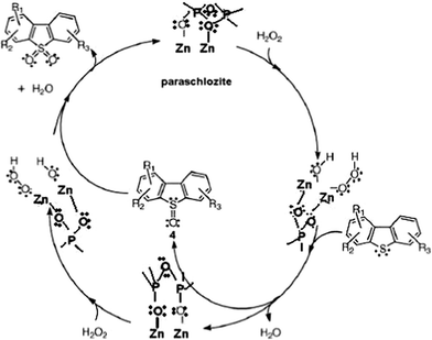 | ||
| Scheme 1 Reaction mechanism for oxidative desulfurization reaction as proposed by García-Gutiérrez et al.60 | ||
4. Conclusions
The present study describes the preparation of Zn catalysts supported on hydroxyapatite material by impregnation and ion exchange techniques using different zinc loadings. The catalysts were tested for the oxidative desulfurization reaction of light gas oil at selected parameters of oxidation temperature: 60 °C, oxidation time: 90 min, oxidant to sulfur molar ratio 2:1 and the oxidized sulfur compounds were adsorbed on bentonite clay materials. Zn/hydroxyapatite catalysts prepared by the ion exchange technique show high activity towards sulfur removal compared with that prepared by the impregnation one. The high surface area, sufficient pore size and the formed paraschlozite phase are the reasons for this activity which reached upto 89.7%.
References
- I. Babich and J. Moulijn, Fuel, 2003, 82, 607 CrossRef CAS.
- Sharipov and V. Nigmatullin, Khimiya i Tekhnologiya Topliv I Masel (in Russian), 2005, 41, 42 Search PubMed.
- L. Hao, Sh. Benxian and X. Zhou, Pet. Sci. Technol., 2005, 23, 991 CrossRef CAS.
- L. Ramirez-Verduzco, F. Murrieta-Guevara, J. Garcia-Gutierrez, R. Saint Martin-Castanon, M. del Martinez-Guerrero, M. del Montiel-Pacheco and R. Mata-Diaz, Pet. Sci. Technol., 2004, 22, 129 CrossRef CAS.
- O. González-García and L. Cedeño-Caero, Catal. Today, 2009, 148, 42 CrossRef.
- A. Chellamani, P. Sengu, N. Mohamed and I. Alhaji, J. Mol. Catal. A: Chem., 2010, 317, 104 CrossRef CAS.
- B. Pawelec, R. Navarro, J. Campos-Martin and J. Fierro, Catal. Sci. Technol., 2011, 1, 23 CAS.
- C. Lanju, G. Shaohu and Z. Dishun, Chin. J. Chem. Eng., 2007, 15, 520 CrossRef.
- X. Yan, P. Mei, J. Lei, Y. Mi, L. Xiong and L. Guo, J. Mol. Catal. A: Chem., 2009, 304, 52 CrossRef CAS.
- S. Kumagai, H. Ishizawa and Y. Toida, Fuel, 2010, 89, 365 CrossRef CAS.
- H. Song, G. Li, X. Wang and Y. Xu, Catal. Today, 2010, 149, 127 CrossRef CAS.
- H. Song, G. Li, X. Wang and Y. Chen, Microporous Mesoporous Mater., 2011, 139, 104 CrossRef CAS.
- K. Haw, W. Abu Bakar, R. Ali, J. Chong and A. Abdul Kadir, Fuel Process. Technol., 2010, 91, 1105 CrossRef CAS.
- V. Toteva, A. Georgiev and L. Topalova, Fuel Process. Technol., 2009, 90, 965 CrossRef CAS.
- X. Ma, A. Zhou and C. Song, Catal. Today, 2007, 123, 276 CrossRef CAS.
- Y. Jia, G. Li and G. Ning, Fuel Process. Technol., 2011, 92, 106 CrossRef CAS.
- M. Miyake, K. Watanabe, Y. Nagayama, H. Nagasawa and T. Suzuki, J. Chem. Soc., Faraday Trans., 1990, 86, 2303 RSC.
- R. Zhu, R. Yu, J. Yao, D. M. C. Xing and D. Wang, Catal. Today, 2008, 139, 94 CrossRef CAS.
- Z. Opre, J. Grunwaldt, M. Maciejewski, D. Ferri, T. Mallat and A. Baiker, J. Catal., 2005, 230, 406 CrossRef CAS.
- K. Elkabouss, M. Kacimi, M. Ziyad, S. Ammar and F. Bozon-Verduraz, J. Catal., 2004, 226, 16 CrossRef CAS.
- T. Hara, K. Mori, T. Mizugaki, K. Ebitani and K. Kaneda, Tetrahedron Lett., 2003, 44, 6207 CrossRef CAS.
- S. Sugiyama, T. Shono, D. Makino, T. Moriga and H. Hayashi, J. Catal., 2003, 214, 8 CrossRef CAS.
- R. Tahir, K. Banert, A. Solhy and S. Sebti, J. Mol. Catal. A: Chem., 2006, 246, 39 CrossRef CAS.
- T. Narasaraju and D. Phebe, J. Mater. Sci., 1996, 31, 1 CrossRef CAS.
- E. Tkalcec, M. Sauer, R. Nonninger and H. Schmidt, J. Mater. Sci., 2001, 361, 5233 Search PubMed.
- T. Burgués and R. Clemente, Cryst. Res. Technol., 2001, 36, 1075 CrossRef.
- H. Rietveld, J. Appl. Crystallogr., 1969, 2, 65 CrossRef CAS.
- P. Katikaneni Sai, D. John Adjaye, O. Idem Raphael and N. Bakhshi Narendra, Ind. Eng. Chem. Res., 1996, 35, 3332 CrossRef.
- R. Faria, D. César and V. Salim, Catal. Today, 2008, 133–135, 168 CrossRef CAS.
- F. Mujaji, Y. Kono and Y. Suyama, Mater. Res. Bull., 2005, 40, 209 CrossRef.
- S. Singh and S. Jonnalagadda, Catal. Lett., 2008, 126, 200 CrossRef CAS.
- C. Wei, H. Zhiliang and L. Qianjun, Catal. Commun., 2008, 9, 2509 CrossRef.
- B. Aellach, A. Ezzamarty, J. Leglise, C. Lamonier and J. Lamonier, Catal. Lett., 2010, 135, 197 CrossRef CAS.
- M. Wakamura, K. Kandori and T. Ishikawa, Colloids Surf., A, 2000, 164, 297 CrossRef CAS.
- H. Anmin, L. Ming, C. Chengkang and M. Dali, J. Mol. Catal. A: Chem., 2007, 267, 79 CrossRef.
- J. Ashok, S. Kumar, M. Subrahmanyam and A. Venugopal, Catal. Lett., 2007, 121, 283 CrossRef.
- R. Terpstra and F. Driessens, Calcif. Tissue Int., 1986, 39, 348 CrossRef CAS.
- J. Guerra-López, R. Pomés, C. O. D. Védova, R. Viña and G. Punte, J. Raman Spectrosc., 2001, 32, 255 CrossRef.
- J. Jun, T. Lee, T. Lim, S. Nam, S. Hong and K. Yoon, J. Catal., 2004, 221, 178 CrossRef CAS.
- C. Boucetta, M. Kacimi, A. Ensuque, J. Piquemal, F. Bozon-Verduraz and M. Ziyad, Appl. Catal., A, 2009, 356, 201 CrossRef CAS.
- R. Stulajterová and Ĺ. Medvecký, Colloids Surf., A, 2008, 316, 104 CrossRef.
- Y. Pang and X. Bao, J. Eur. Ceram. Soc., 2003, 23, 1697 CrossRef CAS.
- C. Lamonier, J. Lamonier, B. Aellach, A. Ezzamarty and J. Leglise, Catal. Today, 2011, 164, 124 CrossRef CAS.
- G. Kumar, E. Girija, A. Thamizhavel, Y. Yokogawa and S. Kalkura, J. Colloid Interface Sci., 2010, 349, 56 CrossRef CAS.
- C. Ergun, J. Eur. Ceram. Soc., 2008, 28, 2137 CrossRef CAS.
- K. Nakamoto, Infrared and Raman Spectra of Inorganic and Coordination Compounds Part B: Applications in Coordination, Organometallic and Bioinorganic Chemistry, John Wiley & Sons, New York, 2009 Search PubMed.
- F. Hanna and Z. Hamid, Pigment and Resine Technology, 2003, 5, 19 Search PubMed.
- H. Tanaka, M. Chikazawa, K. Kandori and T. Ishikawa, Phys. Chem. Chem. Phys., 2000, 2, 2647 RSC.
- Z. Boukhaa, M. Kacimi, M. Ziyad, A. Ensuque and F. Bozon-Verduraz, J. Mol. Catal. A: Chem., 2007, 270, 205 CrossRef.
- T. Sridhar, U. Mudali and M. Subbaiyan, Corros. Sci., 2003, 45, 2337 CrossRef CAS.
- R. LeGeros and J. LeGeros, Dense hydroxyapatite, in: An Introduction to Bio-ceramics, World Scientific, Singapore, 1993 Search PubMed.
- G. LeGeros, C. Bleiwas, M. Retino, R. Rohanizadeh and I. LeGeros, Am. J. Dent., 1999, 12, 65 Search PubMed.
- E. Monma, S. Ueno, M. Tsutsumi and T. Kanazawa, J. Ceram. Soc. Jpn., 1978, 86, 590 CrossRef.
- in Adsorption, Surface Area and Porosity, ed. S. Gregg and K. Sing, Academic Press, London, 1982 Search PubMed.
- T. Zepeda, B. Pawelec, J. Fierro, A. Montesinos, A. Olivas, S. Fuentes and T. Halachev, Microporous Mesoporous Mater., 2008, 111, 493 CrossRef CAS.
- T. Zepeda, J. Fierro, B. Pawelec, R. Nava, T. Klimova, G. Fuentes and T. Halachev, Chem. Mater., 2005, 17, 4062 CrossRef CAS.
- N. Elazarifi, M. Aït Chaoui, A. El Ouassouli, A. Ezzamarty, A. Travert, J. Legliseb, L. de Ménorval and C. Moreau, Catal. Today, 2004, 98, 161 CrossRef CAS.
- M. Khachania, M. Kacimia, A. Ensuqueb, J.-Y. Piquemalb, C. Connanb, F. Bozon-Verdurazb and M. Ziyada, Appl. Catal., A, 2010, 388, 113 CrossRef.
- A. Ishihara, D. Wang, F. Dumeignil, H. Amano, E. Qian and T. Kabe, Appl. Catal., A, 2005, 279, 279 CrossRef CAS.
- J. García-Gutiérrez, G. Fuentes, M. Hernández-Terán, F. Murrieta, J. Navarrete and F. Jiménez-Cruz, Appl. Catal., A, 2006, 305, 15 CrossRef.
- Y. Wang, G. Li, X. Wang and C. Jin, Energy Fuels, 2007, 21, 1415 CrossRef CAS.
- Y. Horii, H. Onuki, S. Doi, T. Mori, T. Takatori, H. Sato, T. Ookuro and T. Sugawara, U.S. Pat., 5494572, 1996 Search PubMed.
- L. Ramírez-Verduzco, E. Torres-García, R. Gómez-Quintana, V. González-Peña and F. Murrieta-Guevara, Catal. Today, 2004, 98, 289 CrossRef.
- V. Hulea, F. Fajula and J. Bousquet, J. Catal., 2001, 198, 179 CrossRef CAS.
- A. Venugopal and M. S. Scurrecll, Appl. Catal., A, 2003, 245, 137 CrossRef CAS.
- F. Basolo and R. G. Pearson, Mechanisms of Inorganic Reactions, Wiley, New York, 2nd edn, 1964 Search PubMed.
- R. Burch, E. Holpin, M. Hayes, K. Ruth and J. A. Sullivan, Appl. Catal., B, 1998, 19, 199 CrossRef CAS.
| This journal is © The Royal Society of Chemistry 2012 |