Solar hydrogen production with semiconductor metal oxides: new directions in experiment and theory
Álvaro
Valdés
*ab,
Jeremie
Brillet
c,
Michael
Grätzel
c,
Hildur
Gudmundsdóttir
d,
Heine A.
Hansen
e,
Hannes
Jónsson
df,
Peter
Klüpfel
d,
Geert-Jan
Kroes
a,
Florian
Le Formal
c,
Isabela C.
Man
e,
Rafael S.
Martins
g,
Jens K.
Nørskov
f,
Jan
Rossmeisl
e,
Kevin
Sivula
c,
Aleksandra
Vojvodic
f and
Michael
Zäch
g
aLeiden Institute of Chemistry, Gorlaeus Laboratories, Leiden University, P.O. Box 9502, 2300 RA Leiden, The Netherlands
bInstituto de Física Fundamental (IFF-CSIC), CSIC, Serrano 123, 28006 Madrid, Spain. E-mail: alvaro.v@iff.csic.es
cLaboratory of Photonics and Interfaces (LPI), Ecole Polytechnique Federale de Lausanne, CH-1015 Lausanne, Switzerland. Tel: +41 21 693 51 78
dScience Institute, VR-III, University of Iceland, 107 Reykjavìk, Iceland
eCenter for Atomic-scale Materials Design, Department of Physics, Nano-DTU, Technical University of Denmark, 2800 Kgs. Lyngby, Denmark
fSUNCAT Center for Interface Science and Catalysis, SLAC National Accelerator Laboratory, 2575 Sand Hill Road, Menlo Park, CA 94025, Department of Chemical Engineering, Stanford University, Stanford, CA 94305, USA
gDepartment of Applied Physics, Chalmers University of Technology, SE-41296 Gothenburg, Sweden
First published on 14th November 2011
Abstract
An overview of a collaborative experimental and theoretical effort toward efficient hydrogen production via photoelectrochemical splitting of water into di-hydrogen and di-oxygen is presented here. We present state-of-the-art experimental studies using hematite and TiO2 functionalized with gold nanoparticles as photoanode materials, and theoretical studies on electro and photo-catalysis of water on a range of metal oxide semiconductor materials, including recently developed implementation of self-interaction corrected energy functionals.
Introduction
During the last decades, the increasing worldwide demand for energy along with the evidence of the environmental effect of atmospheric CO2, mainly produced by the combustion of fossil fuels, and other economical and political factors, have urged the search for new and clean sources of energy. In this context, solar energy emerges as the most promising energy source in terms of abundance and sustainability.1 One of the main challenges for the extensive use of solar energy is the variability of sunlight conditions arising from the night hours or the atmospheric and seasonal changes. It is necessary to convert and store the solar energy in order to provide a more uniform energy supply.2 Another main challenge is to convert solar energy to chemical energy in a form that allows its use in mobile applications.Hydrogen is an attractive energy carrier, advantages being its high energy density by weight and the absence of CO2 emissions when used, provided that the hydrogen is produced in a carbon free manner. However, so far the main commercial process for producing hydrogen is steam reforming of methane.3,4Hydrogen can also be produced from coal using gasification technology, but both these methods have the disadvantage that they result in CO2 emission. Carbon free hydrogen production can be achieved by water splitting through an electrolyser powered by photovoltaics, but a potentially more cost effective route is to perform direct photoelectrolysis.5,6 The solar production of hydrogen provides a clean and sustainable carrier of solar energy, so a large research effort is now focused on this method. Most of these studies are concentrated on the development of photoelectrochemical cells (PEC)7,8 that involve a semiconductor photoanode and a metal cathode in an electrolyte. The process results in oxygen evolution at the photoanode and hydrogen evolution at the cathode.
Unfortunately, a material suitable to work as an efficient photo-anode has to meet specific requirements which, despite the large amount of research effort since the pioneering work 40 years ago of J. P. Boddy8 and A. Fujishima7 with TiO2, have not yet been met by any candidate. The requirements include high chemical stability, good visible light absorption, conduction and valence band edges straddling the reduction and oxidation potentials of water and rapid charge transfer, and a high efficiency for converting solar to chemical energy.9
The most extensively studied materials for the photoanode are metal oxides, and among them, TiO2 has received special attention.10–15 However, the overall performance of titania as a solar photoanode is low due to its large band gap of 3.2 eV, which allows only 4% of the solar energy to be absorbed at best. Also, the conduction band of TiO2 lies slightly positive to the hydrogen evolution redox potential. Several strategies are followed to overcome these limitations. New classes of semiconductor materials are continuously being tested in order to use less energetic but more abundant visible light and various cell configurations composed of several semiconductor anodes connected in series are being developed.16,17 Also, the addition of noble metal nanoparticles has been a widely used strategy to enhance the photocatalytic activity of semiconductor photoanodes. Metallic nanoparticles on the semiconductor surface capture photogenerated electrons, thereby increasing the electron–hole pair separation.
In this article, we present some of the most recent advances in the photoelectrochemical water splitting both theoretical and experimental. These advances were made in the framework of the research of the Marie-Curie Research Training Network “HYDROGEN” that also covered topics related to hydrogen storage, presented elsewhere.18 In the first, experimental, part we address the influence of lithographically-fabricated gold nanoparticles on the photoelectrochemical performance of TiO2 photoanodes. With titania being an extremely well studied material, both theoretically and experimentally, we focus here on demonstrating the power of lithographically fabricated model systems to study selected aspects of photochemical energy conversion in great detail. Functionalization with metal nanoparticles has long been known to enhance the photocatalytic activity of titania. The overall activity is, however, decreased if the particle loading exceeds a certain level19 since part of the semiconductor's active surface area is blocked by the metal nanoparticles, and photon absorption in the semiconductor is compromised due to competitive absorption in the metal. Here the influence of gold nanoparticle size and spatial distribution on the optical and photoelectrochemical properties of titania photoanodes has been studied for a selected set of sample geometries. Next, we present some state-of-the-art results on hematite (α-Fe2O3) as photoanode material. Hematite is a more suitable photoanode material than TiO2 due to its much smaller band gap of 2.1 eV which in principle enables conversion efficiencies of up to 16%. Furthermore, its chemical stability in aqueous environments, its widespread availability, and its relatively low cost make it an attractive candidate for water photo-oxidation. However, α-Fe2O3 has been studied for decades and many intrinsic drawbacks toward PEC oxygen evolution have been identified: First, the hole diffusion length is relatively short as compared to the light penetration depth.20,21 Second, the poor oxygen evolution kinetics at the hematite semi-conductor–liquid junction (SCLJ), necessitates the application of a large overpotential. Finally, the position of the conduction band in hematite is too low to allow spontaneous water reduction by the photogenerated electrons. These three main drawbacks of hematite used for water splitting are examined below.
In the second part we present an overview of recent theoretical work. Because theoretical methods for modeling photoelectrolysis of water have not yet reached the same level of maturity as experimental methods, the theoretical work addresses benchmark materials rather than the materials studied experimentally in this work. We first present work dealing with the properties of metal oxides in some reactions associated with the electrocatalytic production of hydrogen such as the oxygen evolution reaction (OER). Next, the treatment of the electrocatalytic OER is extended to that of the photo-oxidation of water on semiconductor surfaces by including the effect of the photoinduced electron–hole pair. Two different methodologies are considered for that. In the first one a periodic model of the system is used and the effect of the photo-induced electron–hole pair on the semiconductor is included as a potential term accounting for the holes at the upper edge of the valence band.22,23 In the second one, a cluster model of the oxide semiconductor is used and the photo-induced electron–hole pair creation is accounted for by considering each reaction step going from a positively charged cluster to a neutral cluster.24
Most of the recent theoretical studies on hydrogen production are based on density functional theory (DFT) methods. DFT has become a widely used tool in calculations of the properties of solids, liquids and molecules.25 However, a number of shortcomings are known in the practical implementations of DFT, particularly in those commonly used to study solids, such as the generalized gradient approximation (GGA). This includes the inability to predict band gaps of solids, a tendency to over delocalize defect states and an underestimation of the activation energy for atomic rearrangements—issues that are particularly relevant in the design of photoelectrochemical solar cells. These problems are a consequence of the approximate nature of the energy functional used. In the last section, we therefore discuss an extension of the form of the energy functional, including a self-interaction correction, in order to improve the accuracy of the calculations.
Experimental research
Titania thin film photoanodes with lithographically fabricated gold nanodisks for water splitting
Titania suffers from two major limitations which compromise the photon-to-hydrogen conversion efficiency: its wide bandgap of around 3.2 eV prevents the absorption of visible light, and electron–hole recombination is fast.26The addition of noble metal nanoparticles has been a widely used strategy to enhance the photocatalytic activity of titania. Metallic nanoparticles on the semiconductor surface capture photogenerated electrons, thereby increasing the electron–hole pair separation. On the other hand, their presence covers part of the semiconductor's active surface, and they may compromise photon absorption in TiO2. Consequently, the overall activity is decreased if the particle loading exceeds a certain level.19
Normally, production and loading of metallic nanoparticles have been achieved using wet chemical or electrochemical methods. Although these methods are convenient, they offer limited control on nanoparticle size and spatial distribution, which complicates the interpretation of experimental results. We have therefore fabricated metal–nanoparticle functionalized model photoanodes with excellent control over particle size, spacing and arrangement using electron beam lithography. The influence of these parameters on the optical and photoelectrochemical properties of the photoanodes has been studied for a selected set of sample geometries as detailed in Table 1 and illustrated schematically in Fig. 1.
| Sample | Nanodisk material | Disk diameter/nm | Disk height/nm | Center-to-center spacing/nm | Disk position |
|---|---|---|---|---|---|
| (a) TiO2 reference | n/a | n/a | n/a | n/a | n/a |
| (b) Au 100–200 | Au | 100 | 20 | 200 | Surface |
| (c) Au 100–500 | Au | 100 | 20 | 500 | Surface |
| (d) Au 100–500 Rand | Au | 100 | 20 | n/a | Surface |
| (e) SiO2/Au 100–500 | SiO2 + Au | 100 | 20+20 | 500 | Surface |
| (f) Au 100–500 Sand | Au | 100 | 20 | 500 | Embedded in TiO2 |
| (g) Au 250–500 | Au | 250 | 20 | 500 | Surface |
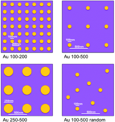 | ||
| Fig. 1 Schematics illustrating gold nanodisk size, spacing and mutual arrangement for different sample geometries. Illustrations are roughly to scale. See Table 1 and text for a more detailed description of the samples. | ||
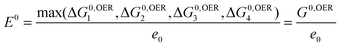
Samples were imaged using scanning electron microscopy and atomic force microscopy, as exemplified in Fig. 2 for sample (g) Au 250–500. A J.A. Woollam M2000 ellipsometer was used to measure the optical properties of the titania films. The total light absorption was determined using a Cary 5000 photospectrometer operated in transflectance mode. The photoelectrochemical behavior was evaluated by recording I–V characteristics in a three-electrode configuration with 1 M NaOH (pH 13.6) as electrolyte, a Pt-wire counter electrode and a Ag/AgCl reference electrode. The potential was scanned at 50 mV s−1 between −1000 and 500 mV versusAg/AgCl. The samples were illuminated from the front side with a 100 W Hg lamp (Newport, ozone free) using a 0.5 neutral density filter.
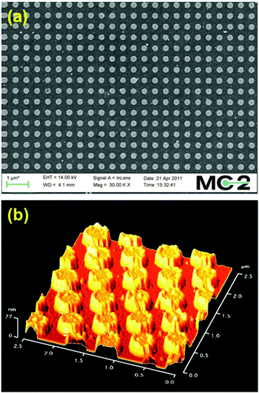 | ||
| Fig. 2 Scanning electron (a) and atomic force (b) microscopy images of sample (g) Au 250–500. | ||
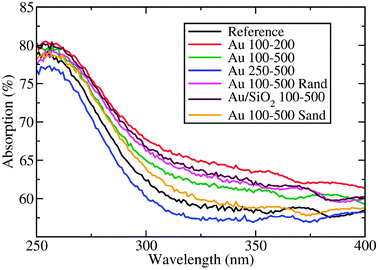 | ||
| Fig. 3 Total absorption of various gold/titania photoanodes in the TiO2 bandgap region. See Table 1 and the text for a description of sample geometries. | ||
The photocurrent densities deriving from water splitting for the different photoanodes are shown in Fig. 4. The presence of metallic nanoparticles, and their distribution, size, and surface coverage, affect the performance of the TiO2 photoanodes.
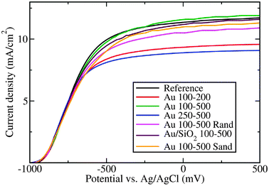 | ||
| Fig. 4 I–V characteristics of all studied photoanodes under illumination from a 100 W Hg arc lamp. See Table 1 and the text for a detailed description of sample geometries. | ||
Samples possessing a high density of nanodisks on their surface (Au 100–200 and Au 250–500) performed the worst, since the titania surface area available for the reaction is largely reduced and light absorption in the gold competes with absorption in titania. The slightly better performance of Au 100–200 as compared to Au 250–500 is attributed to the antireflective properties of 100 nm nanodisks mentioned above. The Au 100–500 sample has a slightly higher photocurrent density than the reference sample, which is a consequence of improved light absorption and improved interfacial charge transfer kinetics due to the presence of the nanodisks.28 In this case, the nanodisk coverage is small enough for the increased overall absorption to compensate for a negative effect of having less titania surface area available. Since the silicon dioxide layer acts as an insulating layer between the titania and the gold, interfacial charge transfer is hindered in the case of SiO2/Au 100–500, explaining the somewhat reduced performance as compared to the case without SiO2 (Au 100–500).
Although photospectrometry measurements showed that gold nanoparticles embedded in the TiO2 photoanode (Au 100–500 Sand sample) lead to an increased total absorption, the photoelectrochemical activity is somewhat smaller than for the reference titania. This is likely due to charge carriers being trapped in the embedded gold nanoparticles.
Finally, the effect of the particles' mutual arrangement on photocurrent generation was analyzed. Despite identical nanodisk coverage, the Au 100–500 sample presented the best performance among all samples tested in this work, whereas its random counterpart (Au 100–500 Rand) displayed considerably smaller photocurrents. This observation indicates that judiciously designed nano-architectures might provide a way towards the more efficient use of expensive noble metal co-catalysts. The detailed mechanism underlying the observed differences is subject of further investigations.
Hematite (α-Fe2O3)
As stated above, hematite is very attractive as photoanode material in terms of band gap (2.1 eV absorbing 16% of solar energy), chemical stability in aqueous environment, availability, and its relatively low cost.29 However, it has some intrinsic drawbacks. First, the hole diffusion length is relatively short compared to the light penetration depth. This causes most electron–hole pairs to recombine if photogenerated holes are not produced close to the semiconductor–liquid junction SCLJ. The balance between having small feature size to ensure charge generation close to the SCLJ but also having films thick enough to absorb a sufficient amount of solar photons brings the need to develop and control the morphology of such films at the nanometre length scale. Second, application of a large overpotential is required to observe water splitting photocurrent due to the slow oxygen evolution reaction (OER) caused by surface traps and poor OER kinetics30. Fig. 5 describes the expected effect of the application of nanostructuring and catalytic31,32 (surface) strategies on the hematite current–voltage response. Finally, the position of the conduction band in hematite is too low to allow spontaneous water reduction by the photogenerated electrons.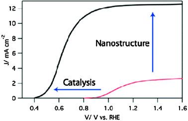 | ||
| Fig. 5 Typical current–voltage response of a hematite photoanode under solar irradiation. The red curve shows the performances of the state-of-the-art atmospheric pressure chemical vapor deposited sample as of 2006. The black curve represents the response of an ideal photoelectrode. The effect of nanostructuring and catalysis strategies are depicted as enhancing the plateau photocurrent and reducing the onset of the photocurrent, respectively.44 (Copyright Wiley-VCH Verlag GmbH & Co. KGaA. Reproduced with permission.) | ||
This last drawback is addressed by assembling the hematite photoanode in a tandem device where a photocathode or an inexpensive photovoltaic (PV) cell (e.g. a Dye-Sensitized Solar Cell, DSC) is connected in series to apply extra bias for completing the water splitting reaction, as shown in Fig. 6. However, given the current state of the art in hematite and PV devices, two PV devices are needed to afford overall water splitting.33 In this case, DSCs have the advantage of only absorbing part of the visible light, especially with the development of new organic dyes having absorption spectral selectivity. This prerogative permits different tandem architectures to be studied. Three possible configurations of a hematite/2DSC tandem device were compared.17 First, the “back DSC” features two DSCs side-by-side collecting the light transmitted by the hematite photoanode. This structure allows the use of a broad range of different dyes. Second, the “front DSC” geometry is made possible with sensitizers having a transparent window in the visible like squaraine-based dyes.34 This architecture benefits from the reflections caused by the high refractive index of hematite and allows the growth of photoactive material on low-cost non-transparent substrates, such as metal foils. Finally, the “tri-level” architecture consisting of the superposition of the hematite photoanode, a squaraine dye based DSC, and a panchromatic dye based DSC eliminates the need to construct two DSCs side by side in the complete device. An electro-optical study of these different architectures was performed by measuring the current/voltage response (I–V curves) under solar irradiation (AM 1.5) of each device under appropriate optical filter (top devices) in order to determine the expected operating point (OP) of the full tandem device and therefore the expected overall efficiencies. The transmission and spectral incident photon to current efficiencies (IPCE) at the OP permitted to assess the limiting factors in terms of optical response and internal quantum efficiencies.
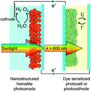 | ||
| Fig. 6 Scheme of the tandem cell approach to solar water splitting. A nanostructured hematite photoanode and a second photocell, here a dye sensitized solar cell, that absorb complementary wavelengths of sunlight, can achieve unassisted water cleavage with only sunlight as an input. | ||
The immediate interpretation of the I–V curves points out the detrimental effect of the late onset potential of the hematite photoanode photocurrent, regardless of the architecture. Even with the voltage from two DSCs, this causes the OP to be far from the maximum power point of the photovoltaic devices and far from the plateau current of the photoanode. Because of this limitation, an estimated STH efficiency of only 1.36% was found (tri-level approach) compared to a possible STH of ca. 4% based on the photocurrent of the hematite electrodes used. This drawback can be addressed by developing surface catalysts and passivation layers to enhance the water oxidation kinetics at the SCLJ, as discussed at the end of this section.
The second finding of this study is the need to enhance the internal quantum efficiency of the hematite photoanode, especially near the band edge. This material absorbs much light in a region where solar photons are abundant yet has poor photon to current conversion efficiency in this same region, leaving only a small portion of the photons available for the device below. This issue can be addressed by controlling the feature size of hematite thin films.
Indeed, as stated before, the photoactivity of hematite is limited by the light penetration depth (α−1 = 118 nm at λ = 550 nm according to Balberg and Pinch21) being much larger than the hole diffusion length (determined by Kennedy et al. as being in the range of 2 to 4 nm). Using a solution processed colloidal approach to make mesoporous films from nanoparticles of a size on the order of the hole diffusion length is an effective strategy to ensure charge photogeneration close to the SCLJ. Sivula et al. have succeeded in making thin film photoanodes based on approximately 10 nm nanoparticles obtained from thermal decomposition of iron pentacarbonyl.35 However, a thermal treatment at 800 °C was found to be essential to obtain photoactivity due to the diffusion and activation of dopant from the substrate. This thermal activation resulted in the sintering of the nanoparticles and an increase of the average particle size up to 75 nm (Fig. 7a). As a result, the maximum photocurrent obtained before the onset of the dark current was only about 1.0 mA cm−2.
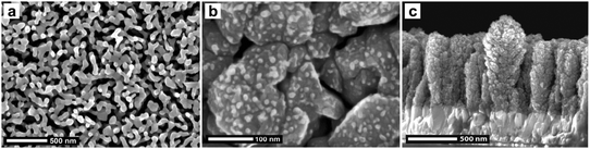 | ||
| Fig. 7 Scanning electron micrographs of hematite samples resulting from different nanostructuring strategies developed to counter-balance the hematite drawbacks for water splitting. (a) Nanoparticle assembly, prepared by gas phase decomposition of Fe(CO)5, deposited on FTO and annealed at 800 °C (similar sample as in ref. 36). (b) The ETA strategy: the iron oxide nanoparticles are seen just starting to cover the WO3 host scaffold (APCVD of Fe(CO)5 at low deposition rate, edge of the deposition spot). (Reprinted in part with permission from ref. 38. Copyright 2011 American Chemical Society.) (c) Cauliflower-like silicon-doped iron oxide photoanodes prepared by APCVD of Fe(CO)5 and TEOS with a carrier gas flow rate of 6 L min−1.42 (Copyright Wiley-VCH Verlag GmbH & Co. KGaA. Reproduced with permission.) | ||
Next, a strategy was developed to permit thermal activation of the photoactive material with control over the morphology.36 By encapsulating the mesoporous film with a conformal and temperature stable rigid scaffold (in this case silica) before thermal activation, it was possible to decouple the feature size and functionality during an annealing process. The subsequent scaffold removal by etching allowed the measurement of the resulting photoelectrode. The water oxidation photocurrent increased by a factor of 49% under standard AM 1.5 illumination. The absorptivity of the hematite thin film also decreased from 67% to 48%, but the IPCE increased from 13% to 24% at 550 nm wavelength. In addition, a morphological annealing step prior to the encapsulation was found to select the best balance between particle connectivity, particle size and surface recombination. This strategy was successful in enhancing the internal quantum efficiency of hematite and could potentially be applied to any kind of complex substrate-based nanostructure where an annealing step is complicated by the sintering and collapse of the architecture.
Another interesting nanostructuring strategy to overcome the discord between the long penetration length of the long wavelengths and the small positive charge diffusion length is to deposit an iron oxide layer, with a thickness similar to this material characteristic, onto a conductive, transparent and high surface area substrate. The so-called “ETA approach” (“Extremely Thin Absorber,” or host–guest) consists therefore in decoupling the light absorption/reaction center role, played by iron oxide in this configuration, and the electron transport role to the external circuit, played by another semiconductor.
This concept increases the efficiency of long wavelength conversion, as expected, with using tungsten trioxide porous thin films as host.37,38 Thin films of WO3 with high roughness were deposited with atmospheric pressure chemical vapor deposition (APCVD) onto conductive glass substrates and subsequently covered with the APCVD of Fe2O3 using iron pentacarbonyl. This led to the formation of a conformal α-Fe2O3 layer (see nucleation of hematite particles on WO3 crystallites in Fig. 7b). When using this configuration with a 300 nm thick tungsten trioxide film and a 60 nm iron oxide layer, a ca. 20% increase in photocurrent was observed as compared to only Fe2O3 control devices. This enhancement was confirmed with absorbed-photon-to-current efficiency measurements, which showed increased quantum efficiency, especially for the wavelengths near the band edge where absorbed photons have the longest penetration depth. Thus, the ETA strategy has been successfully employed for water splitting. Additionally, use of a more appropriate host material than WO3, which partly absorbs visible light with a band gap of 2.6 eV, should lead to even greater enhancement of the photoanode performance. The results presented in this study have also been limited by the minimum thickness of iron oxide required to observe photoactivity of the device. It was observed that a 60 nm thick hematite layer (10 times the hole diffusion length)20 was needed for the water splitting reaction to occur. This is probably due to crystallographic and electronic issues at the interface between the iron oxide and the substrate, with formation of a “dead layer”.39
This same interface has been scrutinized by inserting a buffer layer between the hematite thin film and the substrate. Different materials have been tested in this configuration, but the greatest enhancement of the iron oxide thin film photoelectrochemical properties has been obtained when using an ultrathin layer of silicon sub-oxide.40Tetraethyl orthosilicate (TEOS) is decomposed when sprayed onto the fluorine tin oxide (FTO) substrate heated at 550 °C. FTIR and XPS experiments confirmed that the reaction of TEOS with the substrate surface formed an ultrathin layer of silicon sub-oxide. This reaction was self-limiting, most likely by the availability of the basic sites on the FTO surface, which resulted in only a monolayer of SiOx formed. This modification of the FTO surface dramatically enhanced the photoactivity of iron oxide thin films deposited by spray pyrolysis of iron acetylacetonate, Fe(acac)3. Thus, photocurrent was already observed from a thickness of 12.5 nm when iron oxide was deposited on the TEOS pretreated substrate whereas 23 nm were required on bare conductive glass. The morphological analysis of these thin films suggested that the difference is due to separate film formation processes: a Franck–van der Merwe growth (compact film) on the SiOx modified substrate compared to a Volmer–Weber growth mode (island formation) on the bare FTO substrate. This difference also causes different film properties as the film grown on the modified substrate exhibited more crystallographic organization and less energetic traps at the interface with electrolyte. It was demonstrated40 that control of nucleation and growth of the iron oxide layer was achievable with modifying the substrate surface, leading to increased water-splitting photocurrents. This also suggests that control of the hematite/substrate interface is essential to allow use of iron oxide extremely thin films for water splitting, possibly in the framework of a host–guest approach.
The last nanostructure presented here also shows evidence of the importance of interfaces for the use of α-Fe2O3 photoanodes in a water splitting device. Cauliflower-like nanostructures of silicon doped iron oxide photoanodes are obtained from the APCVD of iron pentacarbonyl and TEOS, according to the method developed by Kay et al.41 (see Fig. 7c). This method has been optimized by increasing the carrier gas flow rate, enhancing the state-of-the-art photoanode performance: an onset potential of 1.0 V vs. the reversible hydrogen electrode (RHE) was achieved and a photocurrent plateau of 3.2 mA cm−2 was reached at a potential of 1.3 V vs. RHE. Investigation of many of the APCVD parameters led to a better understanding of the unequalled performance of these photoanodes.42 The increase in performance was attributed to a higher aspect ratio of the single cauliflower-like nanostructures and to a more pronounced preferential alignment of the highly conductive (001) basal plane of hematite normal to the substrate.
Further amelioration of the system was obtained by depositing a catalyst on top of the hematite nanostructure. While cobalt-based catalysts have been used before,41,43 electrophoretically depositing iridium oxide nanoparticles atop the hematite nanostructure gave the largest improvement reported to date. The catalyst deposition brought the hematite-based device to unprecedented performance for an oxide semiconductor photoanode as the photocurrent onset was cathodically shifted by 200 mV to reach 800 mV and the photocurrent density was measured to be >3 mA cm−2 at an applied potential of 1.23 V versusRHE under AM 1.5 G illumination.44 Even though the onset potential was significantly decreased with the catalyst (from 1.0 V to 0.8 V vs. RHE), the difference between the observed and the theoretical value (0.5 V based on measured flat band potential) remains important and further suggests that other processes occurring at the SCLJ delay the onset of the photocurrent. This additional loss is likely to be caused by the trapping of photogenerated charges at surface states.45
The coating of a cauliflower-like hematite photoanode by an ultrathin layer of alumina, deposited by atomic layer deposition, also results in significant decrease in the overpotential required to photo-oxidize water.46 The detailed investigation into the effect of the alumina overlayer by electrochemical impedance spectroscopy, transient photocurrent and photoluminescence spectra revealed significant modification of the surface capacitance and radiative recombination, which discredit any possible catalytic effect and provide convincing evidence of surface trap passivation. In addition to presenting the best water-splitting photocurrent density obtained with hematite at 0.9 V vs. RHE, this study efficiently decoupled the reasons for the large required overpotential for the water oxidation reaction into surface charge trapping and slow oxygen evolution reaction kinetics and introduced a new method (ALD of oxide layers) to passivate surface traps on hematite photoanodes.
Within this work on hematite photoanodes, different nanostructuring approaches were followed and exhibited, as expected, an increase in the light to current efficiencies especially at wavelengths near the band gap. The overpotential required to observe water photolysis has also been successfully decreased with decoupling its origin in two phenomena: OER catalysis and surface trap passivation.
Additional strategies to nanostructuring for reducing the distance photogenerated carriers have to diffuse to reach the SCLJ have been pursued. In spirit with the work reported in the preceding section with TiO2, metal nanoparticles, 20 nm gold nanoparticles produced by flame pyrolysis of a gold chloride salt in this case, have been incorporated in the bulk and on the surface of hematite thin film. This study highlighted the key role of the overlap between the hematite absorption spectrum and the plasmonic resonance of the nanoparticles to increase local absorption close to the SCLJ. However, performance enhancement of the photoanode for water splitting has not been observed, likely due to the increase in photogenerated charges recombination at the metal semiconductor interface.47
Theoretical research
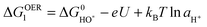
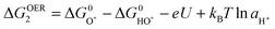
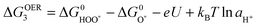
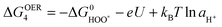
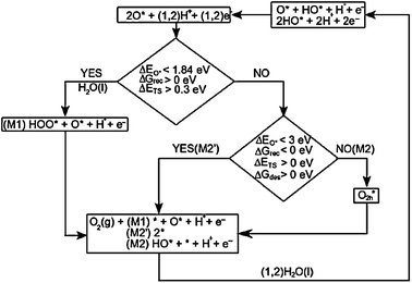
As pointed out in the experimental part on hematite photoanodes, the oxygen evolution reaction is subject to larger overpotentials, which limits the performance of many metal oxides in practical applications. Detailed knowledge concerning the origin of this overpotential and ways to reduce it to a minimum are therefore essential. While these issues are rather difficult to be addressed experimentally (e.g. due to short lifetimes of reaction intermediates), theoretical approaches are very powerful in this respect since they allow one to access individual reaction steps and reaction intermediates. This has prompted us to study the OER using theoretical tools. Also, the relation of the OER with the photo-oxidation of water on semiconductor surfaces is studied and, finally, an extension of the form of the energy functional design to overcome the limitations of the GGA functional approximations to correctly describe defect states and band gap energies is presented.Descriptor OER for catalyst screening
The overall reaction for oxygen evolution is the following:| 2H2O + electricity → O2 + 2H2 | (1) |
| ΔG0w,298 = 4e × 1.23 V = 4.92 eV | (2) |
The overall reaction is divided in two half redox reactions. The hydrogen evolution reaction (HER) occurs at the cathode with the standard equilibrium potential 
Cathode:
| 4H+ + 4e− ↔ 2H2(g) | (3) |
 (vs. SHE):
Anode:
| 2H2O ↔ O2 + 4H+ + 4e− | (4) |
We present a recently developed theoretical model to study the trends in OER overpotential for different materials. The concepts have been developed in the previous papers48–51 and reviews.52,53 We found that the variations in activity for oxygen evolution can be explained in terms of a single ‘descriptor’, namely the free energy change ΔG of one of the intermediate steps along the OER reaction. The derivation of this descriptor is based on a four intermediate steps reaction path. Later we will discuss other reaction paths, but the path below turns out to be the relevant one for most catalysts. These steps are: firstly, a water molecule is oxidized, one proton and one electron are released and a HO* intermediate is formed:
| H2O + * ↔ HO* + H+ + e− | (5) |
 | (6) |
| HO* ↔ O* + H+ + e− | (7) |
 | (8) |
| H2O + O* ↔ HOO* + H+ + e− | (9) |
 | (10) |
| HOO* ↔ * + O2(g) + H+ + e− | (11) |
 | (12) |
Each step includes a proton and an electron transfer and the free energy of the reaction steps varies with the applied potential (U) and the pH. We are only interested in the trends in overpotential, which is determined by the step that has the highest change in free energy. Since the change in free energy of all steps depends on potential and pH in the same manner as the equilibrium potential does, the overpotential value is independent of these two parameters. For notational simplicity, we report the changes in the free energy at U equal to zero, and aH+ = 1 or pH = 0 at room temperature.
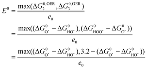
Kinetic barriers between intermediates may play a role, but this is not included in the model, because we make the basic assumption that the barriers scale linearly with the reaction free energies.55 We expect that the trends found with this analysis based on the reactivity of the surface are quite robust, due to cancellations of errors when similar systems are compared and due to the fact that activation barriers are determined by the reactivity. The sum of the free energy of the reaction steps equals the formation energy of O2: 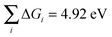 . The intermediate step with the highest reaction free energy is the potential determining step:
 | (13) |
This means that the overpotential is zero if and only if ΔG1 = ΔG2 = ΔG3 = ΔG4 = 1.23 eV and this would define the ideal catalyst. HO*, O* and HOO* are the intermediates during the OER. Therefore the difference between the HOO* and the HO* levels for the ideal case is 2.46 eV, with the O* level placed in the middle. This is illustrated in Fig. 8 by the solid black line and in Fig. 9 by the red stars. However, in a recent review by M. T. M. Koper53 it was pointed out that the binding energies ΔEHO* and ΔEHOO* generally differ by about 3.2 eV for both metals and some oxides.50,51![[thin space (1/6-em)]](https://www.rsc.org/images/entities/char_2009.gif) † This was confirmed recently for a wide range of oxides.54 Here, this is illustrated for rutile oxides and WO3 in Fig. 9, where the adsorption free energies of HOO*, HO* and O* are plotted vs. the adsorption free energy of HO*. It is seen that the energies scale with each other. Due to the approximately constant difference between
† This was confirmed recently for a wide range of oxides.54 Here, this is illustrated for rutile oxides and WO3 in Fig. 9, where the adsorption free energies of HOO*, HO* and O* are plotted vs. the adsorption free energy of HO*. It is seen that the energies scale with each other. Due to the approximately constant difference between  and
and  the approximate minimum obtainable overpotential is given by: (3.2 eV − 2.46 eV)/2e ≈ 0.4 V. As indicated in the previous study the standard deviation is ∼0.2 V. It is therefore desirable to have the
  level in the middle between
  and
and  , in order to get as close as possible to the minimum 0.4 V overpotential.
 | ||
| Fig. 8 The free energy diagram for the OER ideal catalyst. All free energies of the intermediate steps have the same magnitude and are equal to 1.23 V (black continuous line). Red lines indicate the actual HOO* and HO* levels for the catalysts, which, in order to get closer to the ideal ones, have to be moved down and up, respectively, by about 0.37 eV. Unfortunately, when the metal oxide catalyst is changed these two levels tend to move in the same direction with the same magnitude (as indicated by the red and blue arrows). For the OER the way the O* level is positioned between the HOO* and HO* levels determines the potential determining step. | ||
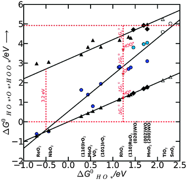 | ||
| Fig. 9 HOO*, O*, HO* binding free energies on rutile surfaces (110 and 101 crystal surface orientations) and for WO3 (200,020,002). Filled symbols represent the adsorption energies on the surfaces with a high coverage of oxygen. The hollow symbols represent adsorption energies on the clean surfaces with no nearest neighbors. Triangles are for HOO* and HO* species, while the circles are for O* species. The difference between the two red dashed horizontal lines is the standard free energy for oxygen molecule to be formed. The differences between the free energy of intermediates give the free energy of each proposed intermediate step as related by eqn (6), (8), (10) and (12). All data were reproduced from I. C. Man et al.,54 A. Valdes and G.-J. Kroes.23 | ||
For the most active catalysts the possible potential determining step is one of two intermediate steps: HO* oxidation to O* or O* oxidation to HOO*. The potential associated with the potential determining step becomes:
 | (14) |
 is very close to the
  level. For weak binding, the O* level gets closer to the HOO* level. For the best catalysts the
  is in the middle. This is illustrated graphically in Fig. 9 where the difference between the two horizontal red dashed lines indicates the formation free energy for an oxygen molecule, while the difference between two consecutive vertical points corresponds to the free energy of each proposed intermediate steps (ΔG01,ΔG02,ΔG03,ΔG04, graphically depicted for the ideal catalyst by the distances between the red stars). In most cases the potential determining step is indeed one of the two intermediate steps indicated in eqn (14).
Therefore we choose  as a good descriptor of the overpotential trends. This is illustrated in Fig. 10. The most active catalysts at the top of the volcano are: RuO2, IrO2, MnO2, PtO2 and RhO2. On the left side of the volcano the potential determining step is the formation of HOO*. After the O* level passes the midpoint between the HO* and the HOO* level, the formation of O* becomes the potential determining step and this is on the right side of the volcano. The HO* intermediate present at the surface can be stable close to the H2O/O2 equilibrium potential when the binding strength of the intermediates weakens. Therefore, the number of H bonds increases and the magnitude of the overpotential is shifted slightly towards higher values. The WO3 data were obtained using a different code and setups.23 When added in this scheme they lie on the right side of the volcano confirming the robustness of the analysis.
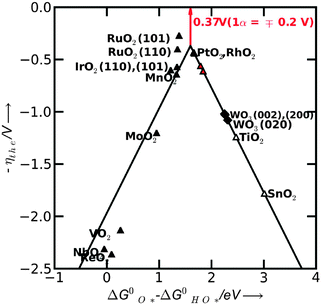 | ||
| Fig. 10 Activity trends for oxygen evolution (OER) on the rutile surfaces (black line). The negative value of theoretical overpotential is plotted against the descriptor for OER (the standard free energy of HO* oxidation). Solid black triangles include the effect of the interaction with the oxygen from the neighboring sites, while the red triangles include the effect of the interaction with the HO* specie. The diamond symbols represent the overpotentials for WO3. The minimum possible overpotential for any oxide is shown by the red arrow (the difference between the peak of the volcano and the zero line). | ||
A direct quantitative comparison between the theoretical and experimental overpotentials cannot be made, due to limitations on both sides.54 However, from a qualitative point of view the trends agree with the experiments.56,57 Some of the oxides are not stable under operating conditions58 and no experimental evidence is available for these oxides. However the theoretical values could be valuable for assessing the activity of oxide mixtures with improved resistance to corrosion.59–62
Close to the top of the volcano, a change of mechanism is possible together with a change of the potential determining step. This feature becomes important only if the magnitude of the free energy of the potential determining step is significantly lower than what was predicted in the present analysis. The reaction path depends on the structure and adsorbates on the surface and these are prone to changes when the binding strength of the intermediates varies from one surface to another. In the following we examine this possible influence on the potential determining step.
We construct the generalized phase diagram48,63 showing the most stable surfaces as a function of potential U and the surface reactivity measured with ΔEO*.The analysis is done at pH = 0 and T = 298 K. The first thing to do is to relate the binding energy of the different surface species to the binding energy of O*, by using scaling relations. This is done for the species O*, O2c*, O2h*, O2v*, shown in Fig. 11, together with their scaling relations. Further on, in Fig. 12a, we depict graphically for three different cases the free energy levels for 2O*, O2h* and O2(g) and the way they affect the activation energy for oxygen recombination (or transition state energy—ΔETS), the free energy of oxygen recombination (ΔGrec) and the free energy of oxygen desorption from the surface to the gas phase (ΔGdes) at room temperature. It is important to remember that the oxygen recombination step is temperature dependent and not potential dependent. If the 2O* and O2h* levels are well below the O2(g) level two cases are possible: if the 2O* level is below O2h*, the recombination and the desorption of the oxygen molecule from the surface are not spontaneous while, in addition, an activation barrier for oxygen recombination has to be overcome (IrO2 case in Fig. 12a). If the recombination becomes spontaneous (the 2O* level is above O2h*), for most of the cases an activation barrier for oxygen recombination still exists and also the desorption of molecular oxygen is not spontaneous (see RuO2 example in the Fig. 12a). If both levels are above the free energy of oxygen in the gas phase, all reactions free energies are downhill in free energy (occur spontaneously), with no activation barrier (see MnO2 example in Fig. 12a).
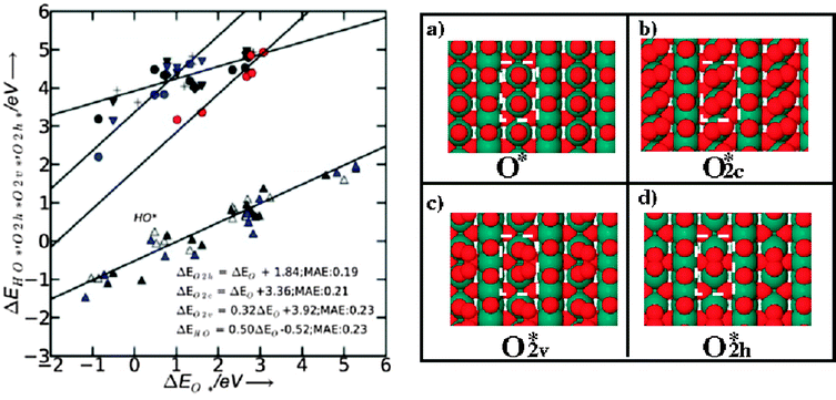 | ||
| Fig. 11 Linear relations for adsorbents formed at CUS sites of rutile (110) surfaces. Hollow, black and blue triangles pointing upwards represent the HO* binding energy on the clean surface, the surface with O*, and with HO* as spectator, respectively. Red circles represent the binding energies for O2h* (oxygen molecule binds between two CUS sites—see the top view of the surface on the right side in the panel d). Black circles, triangles pointing downwards, crosses and squares represent the binding energies of O2v* (oxygen molecule binds vertical on the surface, see right side c panel—top view of the surface) on the clean surface and the surface with O*, HO*, O2v* as next neighbor spectator, respectively. Blue circles, triangles pointing downwards, and crosses represent the binding energies of O2c* on the clean surface and the surface with O* and O2c* as spectator, respectively (see also panel d for a top view). | ||
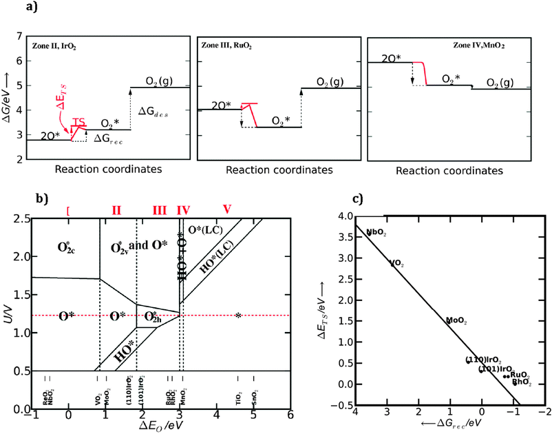 | ||
| Fig. 12 (a) Free energy diagram for IrO2, RuO2 and MnO2 (110) showing the free energy levels of 2O*, O2* and O2 (g) together with the transition state energy for oxygen recombination. (b) Generalized phase diagram calculated at pH = 0 and room temperature. The most stable surfaces are shown for each set of potentials and oxygen binding energies. (LC) means low coverage regime, when the surfaces are partially covered with O* and HO* species. (c) Calculated transition state energies (ΔETS) as a function of recombination energy (ΔGrec). | ||
These concepts will now be generalized for all oxides in the generalized stability surface diagram depicted in Fig. 12b. As expected, at the standard equilibrium potential (1.23 V the red dashed line) the surface structure changes with the strength of the oxygen binding energy. At strong oxygen binding the surface is covered with atomic oxygen (zones I and II). In the limit of the weak oxygen binding, the surface will become covered with molecular oxygen (zone III) because the recombination of oxygen becomes spontaneous (ΔGrec < 0 eV), but oxygen still has to overcome an activation barrier to leave the surface. As mentioned above, this process is not potential dependent, but temperature dependent, therefore, the extent of zones II and III will change depending on the temperature. In Fig. 12c the oxygen activation energy (ΔETS) is plotted against the recombination free energy, ΔGrec. As the recombination energy decreases, the activation barrier decreases as well and approaches zero when the recombination becomes spontaneous (ΔGrec < 0 eV). At a certain value the recombination becomes barrierless. When compared with the oxygen binding energy the trend is the same. The activation energy decreases with decreasing oxygen binding energy and the reaction becomes barrierless when the binding is sufficiently weak. Ir(110) is in zone II, close to zone III with a positive oxygen recombination energy (ΔGrec > 0) and with an activation energy of approximately 0.5 eV (see also the IrO2 example in Fig. 12a). Ir(101) is in zone III, close to the border of zone II. For this surface the recombination free energy is zero, with an activation barrier of approximately 0.3 eV. On RuO2 (110) and (101) the recombination is exothermic with an activation barrier of approximately 0.2 eV and for RhO2(110) the process is barrier less. In the zones where the molecular oxygen binds strongly enough it cannot leave the surface directly. For weaker bindings, the oxygen molecules desorb directly and the surface becomes clean.‡ From the linear relations63 it was found that O2h* = O2 (g) + 2* has ΔGdes < 0 for ΔEO* > 3 eV.
The change of surface configuration of each zone is expected to induce other reaction paths for the OER. In the following we show that this change does not significantly modify the magnitude of the potential determining steps.
 | ||
| Fig. 13 Three main reaction paths through which the OER can proceed. | ||
If we scan through each zone of the phase diagram (Fig. 12b) and in the same time move along the volcano curve (Fig. 10) we find that:
(1) For zone I and II oxygen binds strongly on the surface and the recombination of oxygen is not possible (ΔGrec > 0 eV, ΔETS > 0.5 eV). So the most probable path to follow is the initially proposed mechanism, for which the potential determining step is the formation of OOH. With the exception of MnO2, the oxides on the left side of the volcano are in this zone (see M1 mechanism in Fig. 13).
(2) In zone II the oxygen recombination becomes exothermic with ΔETS decreasing from 0.3 eV to 0. These values are relatively small and the second proposed reaction path including oxygen recombination becomes likely (M2 mechanism in Fig. 13). However, since the oxygen binding at the surface is strong enough, the direct release of oxygen molecules from the surface is not thermodynamically favorable ΔGdes > 0. Therefore, the removal of the oxygen molecule from the surface is the only step that may compete with the other previous potential limiting steps (HOO* to O* or HO* to O*). This competition is possible only in a narrow range of oxygen binding energies close to the top of the volcano. However, at the top of the volcano the potentials of the three possible potential determining steps are believed to be roughly equal, which means that the value of the overpotential will not change much, even though the potential determining step might change.
(3) For zone IV the oxygen recombination is barrierless and the direct desorption of the oxygen molecule from the surface is thermodynamically favorable (ΔGdes < 0, M2′ mechanism in Fig. 13). On the right side of the volcano the overpotential is determined by HO* oxidation, which will be rate limiting also if the mechanism including OOH* formation is assumed.
(4) In zone V the surface coverage with reaction intermediates is low and both reaction paths can be followed. The potential determining step is again HO* oxidation or it can turn out to be also water splitting on the surface, especially when we move to very weak bindings.
We can conclude that for a wide range of oxygen binding energies the potential determining step remains the same. Only at the top of the volcano the flexibility is higher in terms of the potential determining steps, however at the volcano top several steps might have approximately the same magnitude in terms of overpotential. Alternative paths become important for our analysis only if they reduce the overpotential significantly. For determining the overpotential, to a good approximation only the mechanism involving reactions (5), (7), (9), and (11) needs to be considered, even though the actual mechanism might be different and not involve OOH* formation.
Photo-oxidation of water
DFT calculations with periodic boundary conditions were performed for these systems using the atomic simulation environment (ASE) package65 and the ab initio simulation package VASP (Vienna Ab initio Simulation Program) developed at the Institut für Theoretische Physik of the Technische Universität Wien,66–69 respectively.
The free energy differences for the 4 one-electron transfer reaction steps in eqn (5), (7), (9) and (11) are calculated, for pH = 0, as:
| ΔG = ΔE + ΔZPE − TΔS − ΔGU | (15) |
The free energy of the pair H+ + e− is calculated as half the free energy of a hydrogen molecule by considering the reference potential to be that of the standard hydrogen electrode (SHE). This avoids the treatment of charged particles. In addition a potential bias is included on all states involving one electron in the electrode, by shifting the energy of this state by ΔGU = −eU. To study the photo-electrolysis of water we make U = UVB, where UVB is the electrode potential associated with the valence band of the semiconductor relative to the standard hydrogen electrode.
Before analyzing the reaction steps the relative stability of different possible surface coverages is calculated. For TiO2 we have considered the surface with all bridge sites occupied with O (S1), with the fully O-covered surface (S2), the surface with oxygen in the bridge sites and HO* in the CUS sites (S3), the surface fully covered by HO (S4), and the surface that alternates dissociated and molecularly adsorbed water (S5). The free energy of the S1 surface is taken as energy zero. For WO3 we considered SFi where i = 0,1,2,3,4 refers to the surface terminations with i surface tungsten atoms covered with oxygen and F accounts for the different crystal faces (200), (020) and (002). In Fig. 14 we represent the relative stability of the different coverages for the (110) TiO2 surface and the (200) WO3 surface as a function of the applied potential U at pH = 0. In both cases UVB is marked with an arrow. For the (020) and (002) surfaces of WO3 we find results very similar to those ones plotted in Fig. 14 for the (200) surface. According to our calculations for the studied surfaces, at the bias potential corresponding to UVB, which corresponds to strongly oxidizing conditions, the (110) surface of rutile TiO2 and the (200), (020), and (002) surfaces of WO3 are completely covered by oxygen.
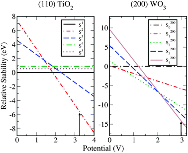 | ||
| Fig. 14 Left panel: the phase-diagram of the H2O + TiO2 (110) surface system calculated as a function of the potential. We compare the free energy of the surface with all bridge sites occupied with O, S1 (ΔG = 0, black line), with the fully O-covered surface, S2 (red line), the surface with oxygen in the bridge sites and HO* in the CUS sites, S3 (blue line), the surface fully covered by HO, S4 (green line) and the surface that alternates dissociated and molecularly adsorbed water, S5 (brown line). The free energy of the S1 surface is taken as energy zero. Right panel: the phase-diagram of the H2O + WO3 (200) surface system calculated as a function of the potential. The surface coverages S200i with i = 0,1,2,3,4 referring to the surface terminations with i surface tungsten atoms covered with oxygen. The free energy of surface with no oxygen on top of the tungsten atoms plus four water molecules is taken as energy zero. | ||
To study the photo-electrolysis using a completely oxygen covered surface we assume the mechanism validated in the previous section for water electrolysis, although we consider the steps to take place in a different order. We take the first step of the reaction to correspond to the oxidation of a water molecule on top of the O* species at the CUS (eqn (9)) to form a superoxide intermediate. In the second step this intermediate is oxidized and the oxygen molecule is formed leaving an empty CUS (eqn (11)). In the third step a water molecule is oxidized on the vacancy forming a OH* intermediate (eqn (5)) and finally in the fourth step the proton is released and the O* species is recovered (eqn (7)). The changes of the free energy at U = 0 V and pH = 0 for the different surfaces are presented in Table 2.
| Step | TiO2 (110) | WO3 (200) | WO3 (020) | WO3 (002) |
|---|---|---|---|---|
| OOH* formation | 1.54 | 0.72 | 0.93 | 0.98 |
| O2 formation | −0.40 | 0.15 | 0.18 | −0.04 |
| OH* formation | 2.01 | 1.78 | 1.47 | 1.70 |
| O* formation | 1.77 | 2.27 | 2.33 | 2.28 |
For TiO2 an overpotential of 0.78 V (V = 1.23 + 0.78 = 2.01) is needed for the rate limiting step H2O + * → HO* + H+ + e−. This result is smaller in comparison with the overpotential of 1.19 V calculated in a previous work51 but still bigger compared to other semiconductor oxides with rutile structures like RuO2 and IrO2 (0.37 and 0.56 V, respectively).51 The difference with the previously calculated overpotential comes from the energetically more favorable peroxo-species at the CUS site for TiO2,71 that was not taken into account in ref. 51. For the other catalysts studied in ref. 51IrO2 and RuO2, the binding of O at the CUS site is much stronger and, therefore, the original structures used in ref. 51 for O* were correct.
The inclusion of the peroxo-species mentioned above at the CUS sites changes the rate limiting step from O* formation to OH* formation. The earlier, incorrect result would imply a large surface coverage with OH*, in contradiction with experimental results.72–74 Moreover, the most favored step is HOO* ↔ * + O2 (g) + H+ + e−. This result explains the experimental difficulties in identifying the HOO* peroxo-species on the rutile samples of TiO2 under conditions where photo-excitation takes place.73
The oxidation of water on the (200) WO3 surface requires an overpotential of 1.04 eV, the overpotential being only slightly higher on the other two other surfaces studied, i.e. 1.10 V for the (020) and 1.05 V for the (002) surface. These overpotentials correspond to a bias of ≈2.3 V on the three surfaces to have every step downhill, and this value is in reasonably good agreement with the experimental findings that electrolysis takes place in the dark for potentials >2.0 V.75 In the three surfaces the rate limiting step for the oxidation process is HO* → O* + H+ + e− suggesting the presence of the reactants (hydroxyl radicals) on the WO3 surfaces. The formation of these radicals upon illumination of WO3 aqueous dispersions has been demonstrated by electron spin detection and spin trapping.76
The free energies of the intermediates for different values of the applied bias, U, for the (110) TiO2 and the (200) WO3 surface are plotted in Fig. 15. As shown in the figure, for no applied bias (U = 0) and for U = 1.23 V (which is the difference between the oxygen and hydrogen evolution redox levels) there are still steps which are uphill in free energy. For TiO2, a bias potential corresponding to the valence band (UVB = 3.25 V) provides enough overpotential for every step in the OER so the photo-evolution of O2 in the TiO2 anode is thermodynamically favorable and kinetically allowed according to our model. This is in agreement with the experimental findings that, in the photoelectrolysis of water using a TiO2 photoanode, the photo-oxidation of water does not need external assistance other than an anodic bias needed to reduce the H+ ions to form H2.77–79
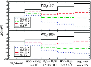 | ||
| Fig. 15 Top/bottom panel: the free energies of the intermediates on the rutile (110)TiO2/monoclinic (200) WO3 surfaces at pH = 0. At the equilibrium potential (U = 1.23 V) some reaction steps are uphill in free energy. At 2.01/2.27 V all reaction steps are downhill in free energy. We also compare to the case with UVB = 3.25/2.97 V, the corresponding values of the redox potential versusNHE for the photogenerated holes in the valence band of TiO2/WO3 in contact with H2O under intense irradiation. | ||
Also for WO3, a bias corresponding to the valence band (UVB = 2.97 V) provides enough overpotential for every step in the OER allowing the photo-evolution of O2 in agreement with the experiments75,80 that observed the oxygen evolution at the photo-anode.
During the last few years, a big effort has been made to study structural and electronic properties of TiO2 nanoclusters from first principles,81–86 but the CUS site of the (110) rutile TiO2 surface was not yet fully described with these clusters. A stochiometric (TiO2)26 cluster that exhibits a rutile structure and exposes a surface much like the (110) surface with a well described CUS has recently been found and used to study the photo-oxidation of water.24 A special effort was made to avoid dangling oxygen atoms because holes tend to localize at these Ti![[double bond, length as m-dash]](https://www.rsc.org/images/entities/char_e001.gif) O structural defects.73 DFT calculations were done using the GAUSSIAN 0387 program for the cluster structure calculations and TURBOMOLE88 for the surface relaxations. The B3LYP functional,89 and the standard LANL2DZ ECP basis set90–93 were chosen. For a better description of the surface species the augmented basis LANL2DZdp was used in the calculation of the intermediates of the photo-oxidation process.
O structural defects.73 DFT calculations were done using the GAUSSIAN 0387 program for the cluster structure calculations and TURBOMOLE88 for the surface relaxations. The B3LYP functional,89 and the standard LANL2DZ ECP basis set90–93 were chosen. For a better description of the surface species the augmented basis LANL2DZdp was used in the calculation of the intermediates of the photo-oxidation process.
The structure of the cluster is shown in Fig. 16 and some of its characteristics are presented below.
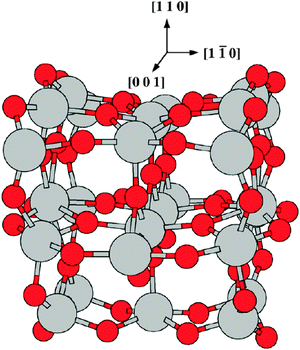 | ||
| Fig. 16 View of the (TiO2)26 cluster. Light grey spheres represent metal ions and red spheres represent oxygen atoms. | ||
The cluster formation energy per TiO2 unit is ECF[(TiO2)26] = E[(TiO2)26]/26 − E[(TiO2)] = 4.83 eV, where E[(TiO2)26] and E[(TiO2)]are the total energies including ZPE corrections of the (TiO2)26 cluster and the free TiO2 molecule, respectively. This value is close to the formation energy of bulk rutile, −5.57 eV,84 and is in good agreement with the value obtained previously for a rutile type cluster with 15 TiO2 units,86ECF = −4.82 eV. This result is also in good agreement with recent periodic DFT calculations of the formation energy of rutile bulk TiO2 that obtained −4.83 eV and −3.97 eV with the PBE-GGA and RPBE-GGA functionals, respectively.94
The band gap estimated from the HOMO–LUMO gap of about 3.05 eV is in good agreement with the experimental value of the rutile TiO2 bulk band gap of 3.0 eV.95 This result is also consistent with the bulk and surface band gaps of 3.2 and 3.7 eV, respectively, obtained from B3LYP periodical calculations.96
In our alternative method to study the OER24 the photo-induced electron–hole creation is accounted for by considering each reaction step going from a positively charged cluster to a neutral cluster. The interaction of the positive hole with the intermediate species on the semiconductor surface is described by means of density functional theory (DFT) calculations so the term related to the redox potential corresponding to the valence band is no longer necessary in the calculation of the free energy.
The steps are now:
| H2O + *+ → HO*n + H+ | (16) |
| HO*+ → O*n + H+ | (17) |
| H2O + O*+ → OOH*n + H+ | (18) |
| OOH*+ → O2 + *n + H+ | (19) |
| ΔG = ΔE + ΔZPE − TΔS + G+H | (20) |
| G+H = ½G(H2) − ΔGe− | (21) |
The reaction free energies at pH = 0 are presented in Table 3 and a diagram of the process is presented in Fig. 17. The rate limiting step is again the formation of the OH* species (eqn (16)) in agreement with the periodic model discussed above.
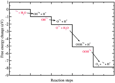 | ||
| Fig. 17 Change of the free energy at pH = 0 for the intermediates of the photo-oxidation of water on the rutile TiO2 (110) using the (TiO2)26 cluster. Every step is indicated with an arrow that goes from a reactant state (in red) to a product state (in black). The black solid line shows the free energy changes at each step. | ||
Every step is indicated with an arrow that goes from a reactant state (in red) to a product state (in black). The black solid line shows the free energy changes at each step. We consider that after each step a new photo-induced electron–hole is produced taking the system to the next reactant state. As seen from Table 3 and Fig. 17 every reaction step is downhill in free energy. Therefore, our cluster calculations also suggest that the illumination of the rutile (110) surface of the TiO2 drives the photo-oxidation of water process spontaneously at the CUS. This is in agreement with the already mentioned experimental finding that, in the photo-electrolysis of water using a TiO2 photo-anode, the photo-oxidation of water does not need external assistance, except the anodic bias needed to reduce the H+ ions formed to H2. The cluster calculations also reproduce the earlier finding from the periodic calculations that OH* formation is the rate limiting step.
This cluster model may form a good starting point for the calculation of possibly existing kinetic barriers between the intermediates of the photo-oxidation of water on the rutile TiO2 (110) surface using a method to locate the transition state, such as the CI-NEB method.97 An advantage of the cluster model is that artefacts due to the interaction of charges with their periodic images, as would occur in periodic calculations, are avoided.
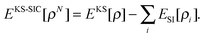
Orbital density dependent energy functionals
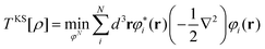
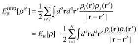
As mentioned in the introduction, commonly used implementations of DFT/GGA have several shortcomings for modeling photoelectrolysis, such as the inability to predict band gaps and tendency to over delocalize defect states. Given the importance of defect states and band gap energies in practical applications, improving theoretical methods with regard to these properties is of great importance in order to be able to exploit the full predictive power of theory to screen large material libraries and to identify interesting novel materials. In this last section, we discuss an extension of the form of the energy functional that includes, as an important component, a self-interaction correction. An application is presented to test the accuracy of the calculated binding energy of an O-adatom at a CUS site and to explore the nature of the O-atom vacancy at the TiO2(110) rutile surface.In the Kohn–Sham approach (KS),98 the energy due to the Coulomb interaction between the electrons, the Hartree energy,
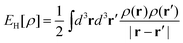 | (22) |
| Eext[ρ] = ∫d3rυext(r)ρ(r) | (23) |
 | (24) |
 | (25) |
 where ρi(r) = |φi(r)|2. Here, N is the total number of electrons in the system. The remaining contributions to the energy, which include the quantum mechanical exchange and correlation energy as well as a correction to the orbital based estimate of the kinetic energy, are combined in EXC[ρ]. This functional is approximated by comparison with numerically exact calculations of the homogeneous electron gas (when using the LDA approximation) and—in most calculations today—also includes the effect of local variations based on the gradient of the density (the GGA approximation):25
| EKSxc[ρ] = ∫d3rεKSxc(ρ, ∇ρ) | (26) |
| EKS[ρ] = TKS[ρ] + EH[ρ] + EKSxc[ρ] + Eext[ρ] | (27) |
Functionals of this type are widely used in the modeling of solids. Various semi-local approximations to EXC[ρ] have been proposed, the GGA functionals, and powerful software packages have been developed utilizing highly efficient optimization algorithms to solve the fundamental minimization problem.99 However, several limitations of the GGA functional approximations have also become apparent:
(a) The predicted total energy is generally not accurate enough, although useful estimates of energy differences can still be obtained in many cases because of cancellation of error. This, however, is problematic when the two systems being compared are qualitatively different. For example, the energy of saddle points (transition states) is typically underestimated compared to the energy of minima (stable states) in estimates of activation energy barriers.100–103
(b) Neither the orbitals nor the energy eigenvalues associated with the orbitals, have a well defined meaning, but the latter are sometimes used in estimates of the ionization energy or the band gap, giving generally poor approximations.
(c) Electronic defect states tend to be overly delocalized and even unstable.104–106
For additional discussions, see ref. 107.
One approach to improve the semi-local approximation is to mix in some Hartree–Fock (HF) exchange through a linear combination with LDA and GGA functionals in so-called hybrid functionals, for example B3LYP and PBE0.108–111 Hybrid functionals can cure some of the deficiencies mentioned above, and their application can lead to improved estimates of binding energies, bond lengths and activation energies.100,103,112 The optimal linear combination coefficients, i.e.mixing parameters, are, however, not the same for all types of systems (for example molecules vs. solids) and these hybrid functionals should be regarded as a semi-empirical approach which relies on tuned cancellation of errors of different origin. For metallic systems, hybrid functionals give poorer results than GGA functionals. Although hybrid functionals are available in most major DFT software packages today, their application to systems with appreciable numbers of electrons, in particular solids with periodic boundary conditions, is hampered by the expensive evaluation of the non-local, orbital-dependent Hartree–Fock exchange. An alternative approach is described below.
The ODD functional form can, in particular, be used to reduce the so-called self-interaction error in KS functionals. The evaluation of the Coulomb energy from the total electron density as in (22) includes interaction of the electrons with themselves, a self-interaction energy. Ideally, the EXC correction term should remove this error as in Hartree–Fock, but in practice the approximations used for EXC in GGA only partly cancel this error. A better estimate of the Coulomb interaction is the orbital density dependent expression
 | (28) |
Perdew and Zunger114 proposed an estimate of the net self-interaction energy for each orbital as
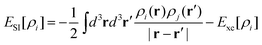 | (29) |
 | (30) |
The orbitals obtained from a ODD functional do not have the arbitrariness associated with the unitary invariance of KS orbitals and the density of each orbital, ρi, could, in principle, give a meaningful estimate of the probability distribution of an electron. Although there have been surprisingly few self-consistent calculations using this functional form in the 30 years since the publication of the article by Perdew and Zunger (compared with the very large number of GGA calculations), it is clear that this functional form can remove several deficiencies of the KS functionals. The reason PZ-SIC has not been used much is in part because of the numerical difficulties in solving the resulting equations and the lack of commonly available software for carrying out such calculations. Another issue is the accuracy of PZ-SIC. Below, we present briefly our approach and applications to TiO2. We emphasize that the algorithms discussed here may be utilized for various functionals of the ODD form, i.e., not just for the PZ-SIC. An efficient algorithm for minimizing ODD functionals115 is described briefly below. Next, an application to adatom binding to the TiO2 surface and the formation of an O-atom vacancy with comparison to results obtained with the GGA approach is described.
We have developed a new algorithm based on explicitly enforcing the requirement for a Hermitian matrix and solving numerically the so-called “localization condition”119 at each iteration. The efficiency of the minimization algorithm depends on fast and reliable solution of this equation.
Also, to make it easier to incorporate ODD functionals into existing DFT codes, which typically rely on the formulation of the minimization problem as an eigenvalue problem,99 it is possible to use a double basis-set approach as has been used in time-dependent calculations.120 A unitary transformation can be chosen in such a way as to optimize the orbital density dependent part of the functional without changing the kinetic energy or any other unitary invariant contribution to the energy. A first set of orbitals, referred to as the energy optimal basis, given by the orbitals {φN}, should converge to the solutions of the ODD problem. The second set of orbitals, the canonical basis-set {ψN}, is used to decouple the defining equations into single-particle equations strictly in the sense of unitary invariant KS-DFT. Both sets of orbitals span the same total density ρ and represent the same kinetic energy T. They are related to each other by a unitary transformation W.
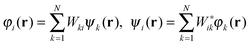 | (31) |
(Ĥ0 + ![[V with combining circumflex]](https://www.rsc.org/images/entities/i_char_0056_0302.gif) k)ψk(r) = εkψk(r) k)ψk(r) = εkψk(r) | (32) |
k is structurally simpler than the non-local exchange operator of exact exchange. The Hamiltonian now becomes unitary invariant with respect to unitary transformations amongst the occupied states {ψN} in a subtle way: Any unitary transformation to the canonic states is simply compensated by an inverse change to W in eqn (31) maintaining the same energy optimal states{φN}. The canonic orbitals can be expected to converge faster than the energy optimal ones as they merely act as a reference set for representing the energy optimal orbitals. The minimization algorithm is explained in more detail elsewhere.115,121
 | (33) |
This is certainly a rough estimate and not the optimal ODD functional, but will be used here to assess the effect of including SIC in the calculations.
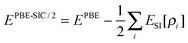
As discussed in previous sections of this paper, an important task for the theoretical calculations is to obtain an estimate of the binding energy of various species on the surface. We have calculated the binding energy of an O-adatom at the CUS site and checked the effect of applying SIC on the calculated binding energy, Eb = Esurface+O − Esurface − EO 2/2. This was done for a perfect surface using the simulation cell illustrated in Fig. 18. The calculated binding energy was 2.18 eV when using PBE and 2.21 eV when using PBE-SIC/2. The application of SIC in this case does not make significant difference. This is surprising given the fact that the binding energy of the O2 molecule is strongly affected:112 it is estimated to be too large by 1.0 eV using PBE, but only by 0.2 eV for PBE-SIC/2. The small effect on the adatom binding energy on the surface is therefore due to cancellation of errors.
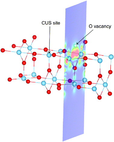 | ||
| Fig. 18 Spin density: an illustration of the simulation cell used in calculations of the rutile TiO2(110) surface. Periodic boundary conditions are applied, but the cell is so long in the direction normal to the surface (see the blue cross section plane) that periodic images in that direction do not interact. The figure shows both the CUS site used for testing the effect of SIC on the O-adatom binding energy, and the O-atom vacancy (the missing O-atom is illustrated with a white sphere). The position of O-atoms is shown with red spheres and that of Ti-atoms with blue spheres. In the calculations presented here, the O-adatom and O-atom vacancy are not present at the same time. The spin density near the vacancy calculated using PBE-SIC/2 is shown with color coding in the cross section plane, red color indicating the highest density. The results show that in the ground, triplet state, two electrons become localized at the site of the vacancy when an O-atom is removed from the surface. | ||
An important aspect of oxide surfaces is the presence of O-atom vacancies. Such a defect on the rutile surface is illustrated in Fig. 18. Associated with these atomic defects are defect electronic states which could play a role in metal island formation127 and catalysis. Considering TiO2 as an ionic solid, the removal of an O-atom will leave the excess electrons of the O-anion behind in the lattice and a central question is how these electrons get distributed.128,129 The PBE calculations predict several electronic states and atomic relaxations that are close in energy but all involve substantial delocalization. For example, there is only a 0.08 eV difference between the singlet and triplet states. The spin density (the difference between electron density of spin up electrons and spin down electrons) in the lower triplet state is shown in Fig. 19. Most of the spin density is at the Ti ions, but it extends over several atoms. The PBE-SIC/2 calculation, however, predicts that the triplet state is 0.5 eV lower in energy and the spin density of the optimal orbitals is localized at the vacancy site, as shown in Fig. 20. The energy eigenvalues (energy of canonical orbitals) obtained from the two calculations is shown in Fig. 21. Note that an estimate of a band gap from the PBE values is much too small, only 1.7 eV as compared with the experimental estimate of the band gap of 3.2 eV. The PBE-SIC/2 calculation, however, gives a somewhat too large estimate of the band gap, 3.7 eV. The two canonical states associated with the defect are significantly lower than the bottom of the conduction band in the PBE-SIC/2 calculation while they are close to the conduction band edge in the in the PBE calculation. These results, however, are tentative as the simulated system was small and effects of periodic boundary conditions could be present.
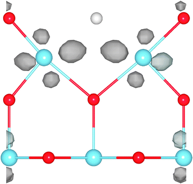 | ||
| Fig. 19 Spin density (grey isosurfaces) near a O-atom vacancy in a triplet state calculated using the PBE functional. High spin density is mainly found near Ti-atoms even at some distance from the vacancy. Color coding of atoms as in Fig. 18. | ||
 | ||
| Fig. 20 Spin density (grey isosurfaces) near a O-atom vacancy in a triplet state calculated using the PBE-SIC/2 functional. High spin density is mainly found at the site of the vacancy. The atoms adjacent to the vacancy are displaced by about 0.1 Å away from the vacancy site during the structural relaxation. Color coding of atoms as in Fig. 18. | ||
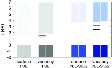 | ||
| Fig. 21 Energy of orbitals in relaxed rutile TiO2(110) surface and in a surface with a O-atom vacancy, calculated for the triplet ground state with PBE functional (gray bars) and with PBE-SIC/2 (blue bars). The zero of the energy is chosen to be at the top of the valence band in each case. The highest energy shown in each case is for the lowest unoccupied state, i.e. bottom of the conduction band. Note the large difference in calculated band gap in the two approximations. When an O-atom vacancy is formed, two states appear in the gap: in the PBE-SIC/2 calculation, the energy of these states is 0.6 eV and 1.2 eV below the conduction band edge, while it is only 0.2 eV and 0.5 eV below the conduction band edge in the PBE calculations. The spin density is mainly localized at the site of the vacancy in the PBE-SIC/2 calculation while it is quite delocalized over several Ti atoms in the PBE calculation, as shown in Fig. 19 and 20. | ||
An important characteristic of the O-vacancy is its formation energy: Eformation = Esurface-O + EO2/2 − Esurface. Here, the results of the two calculations are also quite different, 4.2 eV from PBE and 5.0 eV from PBE-SIC/2. The higher formation energy is consistent with the larger band gap and higher orbital energy of the defect states.
The conclusion of these two preliminary tests of the importance of SIC when modeling the TiO2 surface indicate that the perfect surface and the binding of adatoms and admolecules on the surface are quite well predicted by PBE, but when it comes to the properties of surface defects the SIC makes a substantial difference both on the energy of the electronic defect states and the formation energy. More complete assessment of these issues is being made and will be presented elsewhere.
Conclusions
This paper provides a description of the work on solar hydrogen production developed in the framework of the Research Training Network “HYDROGEN”. Several areas were covered and interesting advances were achieved both on the experimental and theoretical sides.Lithographic methods such as electron beam lithography (EBL) are powerful tools to fabricate metal–semiconductor nanocomposites with excellent control over metal nanoparticle chemistry, size, shape, density and mutual arrangement. Such nanocomposites constitute valuable model systems to study the influence of metallic nanoparticles on the performance of idealized photoanodes for water splitting. To illustrate this, we have shown here that the photoelectrochemical performance of EBL-fabricated gold/titania thin film photoanodes depends critically on the size, density, mutual arrangement and placement of the metallic nanoparticles. It is rather straightforward to extend the approach towards other metal oxides such as hematite. Also, the approach is very suitable to study the mechanism of plasmon-enhanced photochemistry due to the high degree of control it offers, not the least with respect to the size distribution of metallic nanoparticles and the associated inhomogeneous broadening of the plasmon resonance. Here the photoelectrochemical performance of EBL-fabricated gold/titania thin film photoanodes was shown to depend critically on the size, density, mutual arrangement and placement of the metallic nanoparticles. Nanocomposites with randomly arranged gold nanoparticles were found to be inferior to photoanodes with regularly arranged nanoparticles, with all other parameters being identical. This finding indicates that judiciously designed nano-architectures might provide a way towards the more efficient use of often expensive noble metal co-catalysts, thus contributing to the development of cheaper hydrogen production schemes, which are urgently needed for the technology to see a market breakthrough. Certainly EBL will not be the method of choice for the large-scale fabrication of practical metal–semiconductor nanocomposites; other, cheaper methods will have to be considered in order for the additional nanofabrication cost to be offset by larger efficiency and/or reduced noble metal consumption. The conclusions presented here for water splitting are likely to be relevant in the context of other sunlight-driven reactions as well, including for instance carbon dioxide conversion to short hydrocarbon fuels and/or base chemicals, a topic which has recently attracted rapidly growing interest.
The three main drawbacks of hematite for water splitting, i.e. unsuitable conduction band energy for spontaneous hydrogen evolution, the discord between light penetration depth and hole diffusion length and the large overpotential to observe oxygen evolution photocurrent, have been examined. The first limitation can be overcome by using hematite in tandem with other solar cells, such as dye-sensitized solar cells, and different configurations have been compared in order to determine the best design. This study resulted in defining a need for improving water splitting photocurrent density as well as reducing the required potential furnished by the solar cell(s). The increase of the photocurrent density is fully correlated with the second limitation of hematite, which requires photogenerated carriers to be produced close to the SCLJ, motivating the nanostructuring approach. Several different nanostructuring strategies have been developed: nanoparticle assembly, the ETA approach and the cauliflower-type growth produced by APCVD. All of these approaches have shown increased quantum efficiency, especially for the long wavelengths, and the best photoanode performance for hematite to date has been obtained with APCVD samples covered with iridium oxide catalyst (over 3 mA cm−2 at 1.23 V vs. RHE). Additional strategies to nanostructuring for reducing the distance photogenerated carriers have to diffuse to reach the SCLJ, such as increasing local light absorption using gold nanoparticles plasmons, have also been pursued.47 Finally, the required overpotential for oxygen evolution has been demonstrated to originate from two distinct phenomena: slow OER kinetics and the presence of surface states. These issues have been separately addressed by two different means: deposition of IrO2 nanoparticle catalysts and coverage of the hematite surface by a passivating alumina layer.
These studies not only raise the state-of-the-art of using hematite in the field of water splitting but also contribute to the knowledge of this material in general, especially on the role of particle size and on the importance of interfaces. Utilization of the knowledge obtained with this recent work should undoubtedly lead to the use of this abundant and inexpensive material for efficient solar-to-chemical energy conversion.
The oxygen evolution reaction on metal oxide surfaces has been widely studied using theoretical methods. The lowest possible overpotential for oxygen evolution in electrolysis is found to be a consequence of the scaling relations between the different reaction intermediates in the applicable four-step mechanism (eqn (5), (7), (9) and (11)). This results in a lowest possible overpotential of 0.4 V. The overpotential for a given catalyst is determined by the energy difference between the two reaction intermediates OH* and O*. This energy difference was used as a descriptor for the oxygen evolution activity. Based on the structure of the most stable surfaces at the reaction conditions, we discussed the robustness of the analysis if other possible reactions paths are considered. The use of alternative reaction mechanisms may result in slightly different calculated overpotentials, but only for a few catalysts closed to the top of the volcano. Therefore the activity descriptor can be used to screen for better catalysts.
The photo-oxidation of water on semiconductor metal oxides was studied based on the thermochemistry of the reactions using both periodic and cluster models of the materials. In the periodic case the rutile TiO2 (110) surface and the (200), (020) and (002) faces of WO3 were studied. The rate limiting steps were found to be in good agreement with the experimental information available and the experimentally observed spontaneous oxygen evolution in a PEC using these materials as photo-anodes was confirmed theoretically, by adding to the free energy analysis a term accounting for the redox potential corresponding to the valence band of the semiconductor metal oxide surface under irradiation in contact with H2O. A stable (TiO2)26 cluster that resembles bulk rutile, and exhibits a (110) like surface that does not contain dangling oxygen atoms but does incorporate a CUS site, was also used in a somewhat different model to study the photo-oxidation of water on the rutile TiO2 (110) surface. A method, in which every step starts with a reactant state containing a photo-induced positively charged cluster proceeding to a product state containing a neutral cluster plus a proton is used to determine the free energy changes. The main results, including which step is rate limiting and whether the photo-oxidation of water can proceed spontaneously on the TiO2 (110) surface, are consistent with those of the periodic model. This is important because the cluster model forms a good starting point for the study of kinetic barriers, as artifacts arising from Coulomb interactions between charges and their periodic images, which arise in periodic model studies, are avoided.
A minimization procedure was developed for ODD functionals and used in calculations where self-interaction correction was applied to the PBE functional. This methodology opens the way for the development and large scale application of this extended functional form in DFT. The scaling of the computational effort with system size is similar to DFT/GGA and the additional computations lend themselves well to parallel implementation. We find that the self-interaction correction greatly affects the formation energy and electronic structure of the O-atom vacancy at the rutile TiO2(110) surface. The formation energy of the vacancy is increased by 0.9 eV as compared with PBE results and the excess electrons become localized at the site of the vacancy while PBE predicts a more delocalized state with spin density mostly at Ti ions. The binding energy of an O-adatom on a perfect surface is, however, not affected significantly and the various results presented here on the binding of adatoms and admolecules on the rutile surface are, therefore, expected to be reliable and give at least the right qualitative trends.
As a result of the lower level of maturity of the theoretical methods applicable to photo-electrolysis, the theoretical studies addressed benchmark systems rather than the more promising systems addressed in the experiments presented here, such as hematite. However, the study of the OER in electrolysis presented here has offered many useful insights, such as the universal applicability of the four step mechanism used here to analyse the reaction on metaloxides. We have shown that the method also used here to study the OER in electrolysis can be successfully generalised to the study of the photo-oxidation of water. The development of a new, computationally efficient ODD functional incorporating a self-interaction correction offers the perspective of applying the new method for studying photooxidation of water to more promising materials, such as hematite, for which GGA functionals are inaccurate, in future.
Acknowledgements
We thank the EU for financial support of the Marie Curie Research Training Network “Hydrogen” (Contract No. MRTN-CT-2006-032474). In addition, economic support from the Swiss Federal Office of Energy (Project Number 102326, PECHouse), the Foundation for Strategic Environmental Research (Mistra, Dnr 2004-118), the Icelandic Research Foundation, the Danish Center for scientific computing, the Center for Atomic Scale Material Design, the Catalysis for Sustainable Energy (CASE) initiative, the Danish Strategic Research Council's HyCycle program, and the Danish Council for Technology and Innovation's FTP program is also acknowledged. We also thank the Dutch National Computing Facilities Foundation (NCF) for computing resources and Dr S. D. Tilley for his help. JKN, AV, and HJ acknowledge support from the Office of Science of the U.S. Department of Energy to the SUNCAT Center for Interface Science and Catalysis at SLAC.References
- N. S. Lewis, Science, 2007, 315, 798–801 CrossRef CAS.
- T. R. Cook, D. K. Dogutan, S. Y. Reece, Y. Surendranath, T. S. Teets and D. G. Nocera, Chem. Rev., 2010, 110, 6474–6502 CrossRef CAS.
- S. C. Tsang, J. B. Claridge and M. L. H. Green, Catal. Today, 1995, 23, 3–15 CrossRef CAS.
- G. A. Olah, A. Molnar, Hydrocarbon chemistry, 1995 Search PubMed.
- T. Bak, J. Nowotny, M. Rekas and C. C. Sorrell, Int. J. Hydrogen Energy, 2002, 27, 991–1022 CrossRef CAS.
- H. G. Park and J. K. Holt, Energy Environ. Sci., 2010, 3, 1028–1036 RSC.
- A. Fujishima and K. Honda, Nature, 1972, 238, 37–38 CAS.
- P. J. Boddy, J. Electrochem. Soc., 1968, 115, 199 CrossRef CAS.
- R. M. Navarro, M. C. Alvarez-Galvan, J. A. Villoria de la Mano, S. M. Al-Zahrani and J. L. G. Fierro, Energy Environ. Sci., 2010, 3, 1865–1882 RSC.
- M. A. Henderson, Surf. Sci. Rep., 2011, 66, 185–297 Search PubMed.
- F. E. Osterloh, Chem. Mater., 2008, 20, 35–54 CrossRef CAS.
- R. van de Krol, Y. Q. Liang and J. Schoonman, J. Mater. Chem., 2008, 18, 2311–2320 RSC.
- B. D. Alexander, P. J. Kulesza, L. Rutkowska, R. Solarska and J. Augustynski, J. Mater. Chem., 2008, 18, 2298–2303 RSC.
- K. Shankar, J. I. Basham, N. K. Allam, O. K. Varghese, G. K. Mor, X. J. Feng, M. Paulose, J. A. Seabold, K. S. Choi and C. A. Grimes, J. Phys. Chem. C, 2009, 113, 6327–6359 CrossRef CAS.
- L. Vayssieres, On solar hydrogen & nanotechnology, John Wiley & Sons, Asia, 2009 Search PubMed.
- M. G. Walter, E. L. Warren, J. R. McKone, S. W. Boettcher, Q. X. Mi, E. A. Santori and N. S. Lewis, Chem. Rev., 2010, 110, 6446–6473 CrossRef CAS.
- J. Brillet, M. Cornuz, F. Le Formal, J. H. Yum, M. Gratzel and K. Sivula, J. Mater. Res., 2010, 25, 17–24 CrossRef CAS.
- A. J. Churchard, E. Banach, A. Borgschulte, R. Caputo, J.-C. Chen, D. Clary, K. J. Fijalkowski, H. Geerlings, R. V. Genova, W. Grochala, T. Jaron, J. C. Juanes-Marcos, B. Kasemo, G.-J. Kroes, I. Ljubic, N. Naujoks, J. K. Norskov, R. A. Olsen, F. Pendolino, A. Remhof, L. Romanszki, A. Tekin, T. Vegge, M. Zach and A. Zuttel, Phys. Chem. Chem. Phys., 2011, 13, 16955–16972 RSC.
- Z. Yu and S. S. C. Chuang, Appl. Catal., B, 2008, 83, 277–285 CrossRef CAS.
- J. Kennedy and K. Frese, J. Electrochem. Soc., 1978, 125, 709–714 CAS.
- I. Balberg and H. Pinch, J. Magn. Magn. Mater., 1978, 7, 12–15 CrossRef.
- A. Valdes, Z. W. Qu, G. J. Kroes, J. Rossmeisl and J. K. Norskov, J. Phys. Chem. C, 2008, 112, 9872–9879 CrossRef CAS.
- A. Valdes and G. J. Kroes, J. Chem. Phys., 2009, 130, 114701 Search PubMed.
- A. Valdes and G. J. Kroes, J. Phys. Chem. C, 2010, 114, 1701–1708 CrossRef CAS.
- W. Kohn, Rev. Mod. Phys., 1999, 71, 1253–1266 CrossRef CAS.
- M. Takahashi, K. Tsukigi, T. Uchino and T. Yoko, Thin Solid Films, 2001, 388, 231–236 CrossRef CAS.
- B. T. Liu and W. D. Yeh, Thin Solid Films, 2010, 518, 6015–6021 Search PubMed.
- N. Chandrasekharan and P. V. Kamat, J. Phys. Chem. B, 2000, 104, 10851–10857 CrossRef CAS.
- K. Sivula, F. Le Formal and M. Gratzel, ChemSusChem, 2011, 4, 432–449 CrossRef CAS.
- M. P. Dareedwards, A. Hamnett and P. R. Trevellick, J. Chem. Soc., Faraday Trans. I, 1983, 79, 2111–2124 RSC.
- J. Sun, D. K. Zhong and D. R. Gamelin, Energy Environ. Sci., 2010, 3, 1252–1261 RSC.
- L. Duan, L. Tong, Y. Xu and L. Sun, Energy Environ. Sci., 2011, 4, 3296–3313 RSC.
- H. Arakawa, C. Shiraishi, A. Tatemoto, H. Kishida, D. Usui, A. Suma, A. Takamisawa and T. Yamaguchi, in Photovoltaic Cell and Module Technologies, ed. B. VonRoedern and A. E. Delahoy, 2007, vol. 1, pp. XXIX–XXXVIII Search PubMed.
- C. Li, W. Wang, X. Wang, B. Zhang and Y. Cao, Chem. Lett., 2005, 554–555 Search PubMed.
- K. Sivula, R. Zboril, F. Le Formal, R. Robert, A. Weidenkaff, J. Tucek, J. Frydrych and M. Graetzel, J. Am. Chem. Soc., 2010, 132, 7436–7444 CrossRef CAS.
- J. Brillet, M. Grätzel and K. Sivula, Nano Lett., 2010, 10, 4155–4160 CrossRef CAS.
- Y. Lin, G. Yuan, S. Sheehan, S. Zhou and D. Wang, Energy Environ. Sci., 2011 10.1039/C1031EE01850G.
- K. Sivula, F. Le Formal and M. Graetzel, WO3/Fe2O3 Photoanodes for Water Splitting: A Host Scaffold, Guest Absorber Approach, Chem. Mater., 2009, 21, 2862–2867 CrossRef CAS.
- K. Itoh and J. Bockris, J. Appl. Phys., 1984, 56, 874–876 Search PubMed.
- F. Le Formal, M. Graetzel and K. Sivula, Adv. Funct. Mater., 2010, 20, 1099–1107 CrossRef.
- A. Kay, I. Cesar and M. Gratzel, J. Am. Chem. Soc., 2006, 128, 15714–15721 CrossRef CAS.
- M. Cornuz, M. Grätzel and K. Sivula, Preferential Orientation in Hematite Films for Solar Hydrogen Production via Water Splitting, Chem. Vap. Deposition, 2010, 16, 291–295 CrossRef CAS.
- D. K. Zhong and D. R. Gamelin, J. Am. Chem. Soc., 2010, 132, 4202–4207 CrossRef CAS.
- S. D. Tilley, M. Cornuz, K. Sivula and M. Graetzel, Light-Induced Water Splitting with Hematite: Improved Nanostructure and Iridium Oxide Catalysis, Angew. Chem., Int. Ed., 2010, 49, 6405–6408 CrossRef CAS.
- H. Dotan, K. Sivula, M. Gratzel, A. Rothschild and S. C. Warren, Energy Environ. Sci., 2011, 4, 958–964 RSC.
- F. Le Formal, N. Tetreault, M. Cornuz, T. Moehl, M. Gratzel and K. Sivula, Chem. Sci., 2011, 2, 737–743 RSC.
- E. Thimsen, F. Le Formal, M. Grätzel and S. C. Warren, Nano Lett., 2011, 11, 35–43 CrossRef CAS.
- H. A. Hansen, J. Rossmeisl and J. K. Norskov, Phys. Chem. Chem. Phys., 2008, 10, 3722–3730 RSC.
- J. K. Norskov, J. Rossmeisl, A. Logadottir, L. Lindqvist, J. R. Kitchin, T. Bligaard and H. Jonsson, J. Phys. Chem. B, 2004, 108, 17886–17892 CrossRef CAS.
- J. Rossmeisl, A. Logadottir and J. K. Norskov, Chem. Phys., 2005, 319, 178–184 CrossRef CAS.
- J. Rossmeisl, Z. W. Qu, H. Zhu, G. J. Kroes and J. K. Norskov, J. Electroanal. Chem., 2007, 607, 83–89 CrossRef CAS.
- H. Dau, C. Limberg, T. Reier, M. Risch, S. Roggan and P. Strasser, ChemCatChem, 2010, 2, 724–761 Search PubMed.
- M. T. M. Koper, Thermodynamic theory of multi-electron transfer reactions: Implications for electrocatalysis, J. Electroanal. Chem., 2011, 660, 254–260 CrossRef CAS.
- I. C. Man, H. Y. Su, F. Calle-Vallejo, H. A. Hansen, J. I. Martinez, N. G. Inoglu, J. Kitchin, T. Jaramillo, J. K. Norskov and J. Rossmeisl, Chem. Cat. Chem., 2011, 3(7), 1159–1165 Search PubMed.
- V. Tripkovic, E. Skulason, S. Siahrostami, J. K. Norskov and J. Rossmeisl, Electrochim. Acta, 2010, 55, 7975–7981 CrossRef CAS.
- Y. Matsumoto, T. Tazawa, N. Muroi and E. I. Sato, J. Electrochem. Soc., 1986, 133, 2257–2262 Search PubMed.
- S. Trasatti, Electrochim. Acta, 1984, 29, 1503–1512 CrossRef CAS.
- Atlas of electrochemical equilibria, ed. M. Pourbaix, Pergamon Press, 1966 Search PubMed.
- R. Forgie, G. Bugosh, K. C. Neyerlin, Z. C. Liu and P. Strasser, Electrochem. Solid State Lett., 2010, 13, D36–D39 Search PubMed.
- K. Macounova, J. Jirkovsky, M. V. Makarova, J. Franc and P. Krtil, J. Solid State Electrochem., 2009, 13, 959–965 Search PubMed.
- K. Macounova, M. Makarova, J. Franc, J. Jirkovsky and P. Krtil, Electrochem. Solid State Lett., 2008, 11, F27–F29 Search PubMed.
- K. C. Neyerlin, G. Bugosh, R. Forgie, Z. C. Liu and P. Strasser, J. Electrochem. Soc., 2009, 156, B363–B369 Search PubMed.
- H. A. Hansen, I. C. Man, F. Studt, F. Abild-Pedersen, T. Bligaard and J. Rossmeisl, Phys. Chem. Chem. Phys., 2010, 12, 283–290 RSC.
- L. I. Krishtalik, Electrochim. Acta, 1981, 26, 329–337 CrossRef CAS.
- ASE, p. An open source code available at http://wiki.fysik.dtu.dk/ase.
- G. Kresse and J. Hafner, Phys. Rev. B: Condens. Matter Mater. Phys., 1993, 47, 558 CrossRef CAS.
- G. Kresse and J. Hafner, Phys. Rev. B: Condens. Matter Mater. Phys., 1994, 49, 14251 CrossRef CAS.
- G. Kresse and J. Furthmüller, Comput. Mater. Sci., 1996, 6, 15 CrossRef CAS.
- G. Kresse and J. Furthmüller, Phys. Rev. B: Condens. Matter Mater. Phys., 1996, 54, 11169 CrossRef CAS.
- P. W. Atkins, Physical Chemistry, Oxford, UK, 6th edn, 1998 Search PubMed.
- Z. W. Qu and G. J. Kroes, J. Phys. Chem. B, 2006, 110, 23306–23314 CrossRef CAS.
- J. Augustynski, Struct. Bonding, 1988, 69, 1–61 CAS.
- R. F. Howe and M. Gratzel, J. Phys. Chem., 1987, 91, 3906–3909 CrossRef CAS.
- J. Augustynski, private communication.
- H. L. Wang, T. Lindgren, J. J. He, A. Hagfeldt and S. E. Lindquist, J. Phys. Chem. B, 2000, 104, 5686–5696 CrossRef CAS.
- A. Leaustic, F. Babonneau and J. Livage, J. Phys. Chem., 1986, 90, 4193–4198 Search PubMed.
- A. J. Nozik, Nature, 1975, 257, 383–386 CrossRef CAS.
- A. J. Nozik and R. Memming, J. Phys. Chem., 1996, 100, 13061–13078 CrossRef CAS.
- M. Tomkiewicz and H. Fay, Appl. Phys., 1979, 18, 1–28 CAS.
- G. Hodes, D. Cahen and J. Manassen, Nature, 1976, 260, 312–313 CAS.
- S. Hamad, C. R. A. Catlow, S. M. Woodley, S. Lago and J. A. Mejias, J. Phys. Chem. B, 2005, 109, 15741–15748 CrossRef CAS.
- A. Iacomino, G. Cantele, D. Ninno, I. Marri and S. Ossicini, Phys. Rev. B: Condens. Matter Mater. Phys., 2008, 78, 075405 CrossRef.
- M. J. Lundqvist, M. Nilsing, P. Persson and S. Lunell, Int. J. Quantum Chem., 2006, 106, 3214–3234 CrossRef.
- D. J. Zhang, H. Sun, J. Q. Liu and C. B. Liut, J. Phys. Chem. C, 2009, 113, 21–25 CrossRef CAS.
- Z. W. Qu and G. J. Kroes, J. Phys. Chem. B, 2006, 110, 8998–9007 CrossRef CAS.
- Z. W. Qu and G. J. Kroes, J. Phys. Chem. C, 2007, 111, 16808–16817 CrossRef CAS.
- M. J. Frisch, G. W. Trucks, H. B. Schlegel, G. E. Scuseria, M. A. Rob, J. R. Cheeseman, J. A. Montgomery Jr., T. Vreven, K. N. Kudin, J. C. Burant, J. M. Millam, S. S. Iyengar, J. Tomasi, V. Barone, B. Mennucci, M. Cossi, G. Scalmani, N. Rega, G. A. Petersson, H. Nakatsuji, M. Hada, M. Ehara, K. Toyota, R. Fukuda, J. Hasegawa, M. Ishida, T. Nakajima, Y. Honda, O. Kitao, H. Nakai, M. Klene, X. Li, J. E. Knox, H. P. Hratchian, J. B. Cross, V. Bakken, C. Adamo, J. Jaramillo, R. Gomperts, R. E. Stratmann, O. Yazyev, A. J. Austin, R. Cammi, C. Pomelli, J. W. Ochterski, P. Y. Ayala, K. Morokuma, G. A. Voth, P. Salvador, J. J. Dannenberg, V. G. Zakrzewski, S. Dapprich, A. D. Daniels, M. C. Strain, O. Farkas, D. K. Malick, A. D. Rabuck, K. Raghavachari, J. B. Foresman, J. V. Ortiz, Q. Cui, A. G. Baboul, S. Clifford, J. Cioslowski, B. B. Stefanov, G. Liu, A. Liashenko, P. Piskorz, I. Komaromi, R. L. Martin, D. J. Fox, T. Keith, M. A. Al-Laham, C. Y. Peng, A. Nanayakkara, M. Challacombe, P. M. W. Gill, B. Johnson, W. Chen, M. W. Wong, C. Gonzalez and J. A. Pople, Gaussian 03, Revision C.02, Gaussian, Inc., Wallingford, CT, 2004 Search PubMed.
- TURBOMOLE V6.0 2009, a development of University of Karlsruhe and Forschungszentrum Karlsruhe GmbH, 1989–2007, TURBOMOLE GmbH, since 2007; available from http://www.turbomole.com.
- C. Lee, W. Yang and R. G. Parr, Phys. Rev. B: Condens. Matter Mater. Phys., 1988, 37, 785–789 CrossRef CAS.
- T. H. Dunning and P. J. Hay, Modern Theoretical Chemistry, Plenum Press, New York, 1977, p. 1976 Search PubMed.
- P. J. Hay and W. R. Wadt, J. Chem. Phys., 1985, 82, 299 CrossRef CAS.
- W. R. Wadt and P. J. Hay, J. Chem. Phys., 1985, 82, 284 CrossRef CAS.
- P. J. Hay and W. R. Wadt, J. Chem. Phys., 1985, 82, 270 CrossRef CAS.
- J. I. Martinez, H. A. Hansen, J. Rossmeisl and J. K. Norskov, Phys. Rev. B: Condens. Matter Mater. Phys., 2009, 79, 045120 Search PubMed.
- D. C. Cronemeyer and M. A. Gilleo, Phys. Rev., 1951, 82, 975 CrossRef CAS.
- M. Nilsing, P. Persson, S. Lunell and L. Ojamäe, J. Phys. Chem. C, 2007, 111, 12116 CrossRef CAS.
- G. Henkelman, B. P. Uberuaga and H. Jónsson, J. Chem. Phys., 2000, 113, 9901 CrossRef CAS.
- W. Kohn and L. J. Sham, Phys. Rev., 1965, 140, A1133–A1138 CrossRef.
- E. R. Davidson, Comput. Phys. Commun., 1989, 53, 49–60 Search PubMed.
- P. Nachtigall, K. D. Jordan, A. Smith and H. Jonsson, J. Chem. Phys., 1996, 104, 148–158 Search PubMed.
- S. Patchkovskii, J. Autschbach and T. Ziegler, J. Chem. Phys., 2001, 115, 26–42 CrossRef CAS.
- S. Patchkovskii and T. Ziegler, J. Chem. Phys., 2002, 116, 7806–7813 CrossRef.
- J. J. Zheng, Y. Zhao and D. G. Truhlar, J. Chem. Theory Comput., 2009, 5, 808–821 CrossRef CAS.
- R. H. D. Nuttall and J. A. Weil, Can. J. Phys., 1981, 59, 1696–1708 CAS.
- G. Pacchioni, F. Frigoli, D. Ricci and J. A. Weil, Phys. Rev. B: Condens. Matter Mater. Phys., 2001, 63, 054102.
- J. Laegsgaard and K. Stokbro, Phys. Rev. Lett., 2001, 86, 2834–2837 CrossRef CAS.
- S. Kummel and L. Kronik, Rev. Mod. Phys., 2008, 80, 3–60 CrossRef.
- A. D. Becke, J. Chem. Phys., 1988, 88, 1053–1062 CrossRef CAS.
- A. D. Becke, J. Chem. Phys., 1993, 98, 5648–5652 CrossRef CAS.
- A. D. Becke, J. Chem. Phys., 1996, 104, 1040–1046 CrossRef CAS.
- J. P. Perdew, M. Emzerhof and K. Burke, J. Chem. Phys., 1996, 105, 9982–9985 CrossRef CAS.
- S. Kurth, J. P. Perdew and P. Blaha, Int. J. Quantum Chem., 1999, 75, 889–909 CrossRef CAS.
- E. J. Bylaska, K. Tsemekhman, S. B. Baden, J. H. Weare and H. Jonsson, J. Comput. Chem., 2011, 32, 54–69 Search PubMed.
- J. P. Perdew and A. Zunger, Phys. Rev. B: Condens. Matter Mater. Phys., 1981, 23, 5048–5079 CrossRef CAS.
- P. Klüpfel, S. Klüpfel, K. Tsemekhman and H. Jónsson, Lecture Notes in Computer Science, 2011 Search PubMed , accepted for publication.
- R. A. Heaton, J. G. Harrison and C. C. Lin, Phys. Rev. B: Condens. Matter Mater. Phys., 1983, 28, 5992–6007 Search PubMed.
- J. G. Harrison, R. A. Heaton and C. C. Lin, J. Phys. B: At. Mol. Phys., 1983, 16, 2079–2091 Search PubMed.
- S. Goedecker and C. J. Umrigar, Phys. Rev. A: At., Mol., Opt. Phys., 1997, 55, 1765–1771 CrossRef CAS.
- M. R. Pederson, R. A. Heaton and C. C. Lin, J. Chem. Phys., 1984, 80, 1972–1975 CrossRef CAS.
- J. Messud, P. M. Dinh, P. G. Reinhard and E. Suraud, Phys. Rev. Lett., 2008, 101, 096404 Search PubMed.
- P. Klüpfel, S. Klüpfel and H. Jónsson, in preparation.
- J. Enkovaara, C. Rostgaard, J. J. Mortensen, J. Chen, M. Dulak, L. Ferrighi, J. Gavnholt, C. Glinsvad, V. Haikola, H. A. Hansen, H. H. Kristoffersen, M. Kuisma, A. H. Larsen, L. Lehtovaara, M. Ljungberg, O. Lopez-Acevedo, P. G. Moses, J. Ojanen, T. Olsen, V. Petzold, N. A. Romero, J. Stausholm-Moller, M. Strange, G. A. Tritsaris, M. Vanin, M. Walter, B. Hammer, H. Hakkinen, G. K. H. Madsen, R. M. Nieminen, J. Norskov, M. Puska, T. T. Rantala, J. Schiotz, K. S. Thygesen and K. W. Jacobsen, J. Phys.: Condens. Matter, 2010, 22, 253202 CrossRef CAS.
- H. Jónsson, Proc. Natl. Acad. Sci. U. S. A., 2011, 108, 944–949 CrossRef CAS.
- J. Harris and R. O. Jones, J. Phys. F: Met. Phys., 1974, 4, 1170–1186 CrossRef.
- O. Gunnarsson and B. I. Lundqvist, Phys. Rev. B: Solid State, 1976, 13, 4274–4298 CrossRef CAS.
- D. C. Langreth and J. P. Perdew, Phys. Rev. B: Solid State, 1977, 15, 2884–2901 CrossRef.
- L. J. Xu, G. Henkelman, C. T. Campbell and H. Jonsson, Surf. Sci., 2006, 600, 1351–1362 CrossRef CAS.
- P. M. Kowalski, M. F. Camellone, N. N. Nair, B. Meyer and D. Marx, Phys. Rev. Lett., 2010, 105, 146405 Search PubMed.
- S. Chretien and H. Metiu, J. Phys. Chem. C, 2011, 115, 4696–4705 Search PubMed.
Footnotes |
| † ΔEHOO* = 0.53ΔEO* + 3.18 and ΔEHO* = 0.5ΔEO* + 0.05, the effect of water was considered for these values. |
| ‡ Clean means that the surface is covered with undissociated water molecules. |
| This journal is © the Owner Societies 2012 |