Ultra simple catalyst layer preparation for the growth of vertically aligned CNTs and CNT-based nanostructures†
Ricardo M.
Silva
a,
Andrea
Pucci
a,
Catherine
Marichy
a,
Diogo
Mata
b,
Marta C.
Ferro
b,
Rui F.
Silva
b and
Nicola
Pinna
*ac
aDepartment of Chemistry, CICECO, University of Aveiro, 3810-193, Aveiro, Portugal. E-mail: pinna@ua.pt
bDepartment of Ceramics and Glass Engineering, CICECO, University of Aveiro, 3810-193, Aveiro, Portugal
cWorld Class University (WCU) Program of Chemical Convergence for Energy and Environment (C2E2), School of Chemical and Biological Engineering, College of Engineering, Seoul National University (SNU), Seoul, 151-744, Korea
First published on 7th November 2011
Abstract
A simple and rapid route for the preparation of iron-based catalyst layers for CVD growth of carbon nanotubes is introduced. The catalyst was deposited by a microwave-assisted nonaqueous sol–gel process onto silicon wafers with or without an Al2O3 buffer layer and onto colloidal silica spheres. High quality vertically aligned carbon nanotube (VACNT) mats were grown on planar substrates. The versatility of the catalyst preparation is highlighted by the growth of CNTs onto non-planar surfaces such as the silica spheres.
Introduction
Carbon nanotubes (CNTs) have been extensively explored in an attempt to take advantage of their exceptional physical properties for specific applications such as polymer reinforcement, energy storage, microelectronics and catalysis.1,2 A dense mat of vertically aligned CNTs (VACNTs) can be formed if CNTs are efficiently grown by chemical vapor deposition (CVD) from an inorganic catalyst (generally Fe, Ni, Co) deposited on a substrate.3 The vertical alignment is caused by van der Waals forces between CNTs and the high packing density. The CVD approach can be regarded as one of the most promising techniques for VACNTs production, due to its flexibility and scalability up to the industrial level.4,5 Devices based on VACNTs can greatly benefit from the high electron mobility along the CNTs. Moreover, due to the well known CNTs surface chemistry, their surface functionalization allows fine tuning of the chemical and electrical properties, for example.6–8 Finally, it is of utmost importance to address structure–property relationships in CNT based nanostructures. To give just a peculiar example, vertically aligned multiwalled carbon nanotubes (MWCNTs) showed superior electronic conductivity while vertically aligned single walled carbon nanotubes showed superior thermal diffusivity.2,9A generally accepted growth mechanism for VACNTs by CVD is based on the thermal decomposition of a carbon gas source, such as acetylene, in the presence of small catalyst particles (e.g. iron).7 The growth process starts with diffusion of carbon into the metallic iron catalyst particles. When the carbon concentration inside the catalyst attains supersaturation, the precipitation of the excess carbon present in the catalyst leads to the growth of CNTs. Two mechanisms can be observed differing on whether or not the catalyst particle is lifted up during the growth (tip growth and base growth).7,10,11 Due to the role of the catalyst particles, the CNTs diameter can be controlled by their size.7,10,11 Various factors can influence the quality of the VACNTs such as the catalyst, substrate materials, carbon source and the process parameters.
Different techniques can be used to prepare active catalyst for VACNTs growth. Usually, thin metallic catalyst films are deposited by sputtering12–14 or e-beam evaporation.12,13,15 In order to hinder the metal catalyst diffusion into the substrate, or the intermixing of the catalyst and substrate, oxide thin films are used as catalyst supports. Silica and alumina proved to be suitable due to their stability and chemical inertness at the VACNTs growth temperature.3,16
Metal oxide nanostructures can also be used as starting material for in situ catalyst fabrication. In this case, the metal oxide is reduced in situ prior to the CNTs growth. For example, Felisberto et al.17 described the synthesis of an aligned nanotubes array using commercial magnetite nanoparticles. This approach allowed the growth of CNTs in large areas onto the Si substrate and a precise control of the density by simply modifying the concentration of the magnetite nanoparticles.
In order to simplify the catalyst preparation, allowing an industrially viable process, one-pot soft chemistry approaches are sought after. These routes are especially suitable for coating structured substrates such as wires, spheres, tips, etc. In this context, we already showed that non aqueous sol–gel routes are elegant approaches for the synthesis of metal oxide nanocrystals18 and ordered organic–inorganic hybrid materials.19 These routes, involving the reaction of metal oxide precursors in organic solvents (e.g. benzyl alcohol) at moderate temperature and pressure, offer advantages such as high crystallinity of the as synthesized oxides, high purity, high reproducibility and the ability to control the crystal growth without the need of using additional ligands.18,20 The advantages of these approaches for the synthesis of catalyst layers for CNTs growth are their simplicity and the possibility to uniformly coat non-planar substrates and complex nanostructures. Recently, the “benzyl alcohol route”18 was extended to microwave chemistry for the fabrication of nanoparticles in solution and their deposition onto planar substrates.21–23 In this work, we will show that in only few minutes well defined particulate-like catalyst layers can be deposited on various substrates and can be used to efficiently grow VACNTs. As a proof of concept, we will also show that CNTs can be easily grown from colloidal silica nanoparticles coated with a thin layer of iron-based catalyst. The quality and the properties of the CNTs grown from these catalysts will be discussed and compared to the ones obtained from CNTs grown from state of the art catalysts.
Experimental section
Fe(III) acetylacetonate ≥99.9% metals basis, benzyl alcohol ACS ≥99.0%, tetraethyl orthosilicate puriss and ammonium hydroxide ACS reagent 28.0–30.0% NH3 basis were purchased from Sigma-Aldrich, and absolute ethanol PA grade from Panreac. All the chemicals were used as received.Si wafers with 200 nm thermally grown SiO2 with and without an Al2O3 buffer layer of 10 nm, deposited from trimethyl aluminium and water by ALD at 200 °C, were used as substrates for the deposition of iron oxide.
The synthesis of 100 nm silica spheres was carried out by the Stöber method.24 Upon catalyst deposition the spheres were spin coated (1000 rpm, 30 s from ethanol solution of 2 mg mL−1 of silica) on a Si wafer before being introduced into the CVD reactor.
Films of iron oxide particles were prepared by a modified method based on a recent report.23 Briefly, a substrate (wafer or colloidal silica spheres) was introduced into a 10 mL microwave vessel containing a reaction solution of iron precursor in benzyl alcohol. The solution was prepared in a glovebox under inert atmosphere mixing the proper amount of Fe(acac)3 in 7 mL of benzyl alcohol in order to obtain a concentration of 20, 60, and 90 mM, in the case of iron oxide deposition onto silica spheres, silicon wafers with thermally grown SiO2 and silicon wafers with thermally grown SiO2 and Al2O3 ALD, respectively. The reaction mixture was heated by microwave irradiation (CEM Discovery SP) to 170 °C in the presence of the substrate. In the case of the spheres, the solution was stirred in order to obtain a good dispersion. After 10 minutes dwelling, the reaction vessel was cooled down by compressed air flow. The wafers were removed from the solution, washed with ethanol and dried under air at 65 °C. Silica particles were separated by centrifugation and washed with ethanol.
Carbon nanotubes were grown by thermal chemical vapor deposition in a furnace reactor at 750 °C. The CVD set-up consists of a horizontal mounted quartz tube (diameter ≈ 5 cm) coupled with a thermal heater, equipped with various gas lines and standard mass flow controllers to regulate the flow of carbon source (acetylene ≥99.6%), reducing gas (hydrogen ≥99.999%) and inert gas into the furnace (argon). The substrates coated with the catalytic layer were cut into 5 × 5 mm2 and placed into the quartz tube of the furnace. The reactor was evacuated to 3.0 × 10⁻³ mbar with a rotary pump and was subsequently filled with Ar up to atmospheric pressure. The substrate was pulled to the center of the quartz tube and heated to 750 °C under a flow of Ar (1000 sccm) for 5 minutes. Afterwards, H2 (500 sccm) and Ar (100 sccm) were introduced for 1 minute in order to completely reduce the iron oxide catalyst to metallic iron. Immediately after, C2H2 (10 sccm), H2 (100 sccm) and Ar (400 sccm) were introduced for 30 minutes, or less, in the case of the silica spheres. The gas flows were stopped and the sample removed from the furnace and cooled down to room temperature.
Atomic force microscopy (AFM) measurements were performed with a Ntegra Prima, NT-MDT. Scanning electron microscopy (SEM) was performed with a Hitachi SU-70 microscope operated in secondary electron mode at 15 kV. Transmission Electron Microscopy (TEM) measurements were carried out on a Hitachi H-9000 microscope operated at 300 kV. Samples for TEM measurements were prepared by removing the CNTs from the substrates and dispersing them in ethanol. Finally, a drop of this solution was deposited on a holey carbon grid. The XPS experiments were performed in a UHV multipurpose surface analysis system (SIGMA PROBE, Thermo Fisher Scientific, UK) operating at base pressures <10−10 mbar. Raman spectroscopy was carried out at a 532 nm excitation wavelength on the as-grown VACNTs.
Results and discussion
Catalyst layer deposition
The facile synthesis of iron oxide or ferrite nanoparticles by microwave-assisted solvothermal synthesis was recently reported by Bilecka and Niederberger.22 It involves the reaction of Fe(acac)3 in benzyl alcohol at moderate temperature (i.e. lower than 200 °C). The formation of iron oxide occurs under an aldol condensation reaction as previously reported.20,25,26 In this work, the “benzyl alcohol route” was further developed for the deposition of a very thin layer of iron oxide nanoparticles onto silicon wafers with thermally grown SiO2 with and without a terminal 10 nm Al2O3 buffer layer, and colloidal silica spheres. The “benzyl alcohol route” greatly benefits from microwave heating for heterostructure formations. As a matter of fact, the low dipolar moment of benzyl alcohol makes it a bad microwave absorber compared to the substrates used. This allows preferential nucleation of metal oxides onto the substrate in contrast to the homogeneous solution.23,27 In particular, the reaction of a low concentrated solution of Fe(acac)3 in benzyl alcohol (i.e. below 100 mM), in the presence of the substrates, leads to the deposition of a very thin layer of iron oxide nanoparticles. Upon solvothermal reaction the occurrence of the iron oxide deposition could be monitored by the coloration of the wafers changing from the typical light yellow metallic color of SiO2/Si wafers to dark yellow/reddish.Fig. 1 shows the SEM images of the three substrates coated with iron oxide, before and after annealing under hydrogen. Iron oxide nanoparticles deposited onto Al2O3/SiO2/Si and SiO2/Si substrates appear as a granular film made of around 20 nm particles (Fig. 1a and c). The annealing step at 750 °C in Ar and H2 for 1 min leads to a smoothing of the surface with the creation of more isolated particles (Fig. 1b and d). The two different wafers were chosen in order to investigate the effect of the stabilizing Al2O3 buffer layer on the CNT growth process. It is well known that aluminium oxide is a better substrate for stabilizing iron-based catalysts compared to silica.3 This is clearly observable in these experiments as well, where after annealing at 750 °C in the presence of hydrogen the particles remain much smaller in size and are better dispersed on the Al2O3/SiO2/Si substrate (Fig. 1b) compared to SiO2/Si (Fig. 1d). These findings are also in good agreement with AFM studies on the same samples (see below). The same microwave-assisted solvothermal synthesis could be applied to non-planar substrates such as nanoparticles. The deposition onto colloidal silica spheres, 200 nm in diameter, leads to the complete coverage of their surface with a granular iron oxide film (Fig. 1e). The inset shows a TEM image of the same spheres coated with a lower amount of iron oxide highlighting the homogeneous deposition of the nanoparticles. These findings prove that the deposition approach is rather general and can be applied to a large variety of surfaces. After annealing the thin and continuous granular film is converted to isolated nanoparticles of a larger size (Fig. 1f) similarly to the ones obtained on the SiO2/Si wafer (cf.Fig. 1d).
 | ||
| Fig. 1 SEM images after iron oxide deposition (a, c and e) and after annealing treatment (b, d and f) for Al2O3/SiO2/Si, SiO2/Si wafers and silica spheres, respectively. Inset of (e): TEM image of iron oxide coated silica spheres. | ||
Fig. 2a and c show the surface profiles, obtained by AFM, of the as-deposited iron oxide film onto Al2O3/SiO2/Si and SiO2/Si substrates, respectively. These profiles reveal that the initial film consists of a granular film with a root mean square (RMS) roughness of 27 and 23 nm, respectively. Fig. 2b and d show the AFM images of the same substrates after annealing at 750 °C under hydrogen, proving that the annealing step caused the formation of smaller particles and a decrease of the RMS roughness to 11 and 18 nm, respectively. These results are in good agreement with the SEM observations. In order to investigate the chemical composition of the iron nanoparticles X-ray photoelectron spectroscopy (XPS) was carried out on the Al2O3/SiO2/Si and SiO2/Si substrates after iron oxide deposition (Fig. S1†). The Fe 2p core level exhibits broad asymmetric peaks at about 711.0 and 725.0 eV, corresponding to the Fe 2p3/2 and 2p1/2 levels of iron oxide and two satellites centered at 716 and 730 eV. These spectra match better to Fe2O3 than Fe3O4, proving that the microwave-assisted nonaqueous sol–gel approach leads to the formation of Fe2O3 in contrast to what happens in the homogeneous solution.25
 | ||
| Fig. 2 AFM images after iron oxide deposition (a and c) and after the annealing treatment (b and d) for Al2O3/SiO2/Si and SiO2/Si wafers, respectively. | ||
VACNTs growth
Before CNTs growth, the iron oxide was reduced to metallic iron by in situ annealing in the CVD reactor at 750 °C in the presence of H2. In the next step the growth of vertically aligned CNTs begin when the C2H2 is introduced into the reaction chamber. As demonstrated by SEM (Fig. 3a–c), on both wafer substrates VACNTs were grown. The CNTs are generally well vertically aligned although the bottom part of samples appears to be more straight than the middle or the top, which show a curly aspect. Similar morphologies are obtained, independent of the substrate used. Nevertheless, when comparing the VACNTs obtained with the two substrates the role of the Al2O3 buffer layer can be highlighted. On the one hand, the height of the vertically aligned CNTs grown from catalyst supported onto Al2O3 is one order of magnitude larger (419 μm) as compared to the catalyst supported on SiO2 (53 μm), i.e. the growth rates were 14 and 2 μm min−1, respectively. This confirms that, compared to SiO2, Al2O3 is a superior support in order to achieve a good distribution and stabilization of the catalytically active species. These results are in agreement with the ones of Mattevi et al.3 that compared the activity of thin metallic catalyst films, prepared by physical vapor deposition, supported on Al2O3 and SiO2. On the other hand, the density of CNTs is also higher when an Al2O3 buffer layer is present, leading to better aligned CNTs (cf.Fig. 3b and c). TEM studies reveal the formation of homogeneous MWCNTs of 20 nm in diameter (Fig. 3d and e). The high resolution TEM image (Fig. 3e) shows the highly graphitic walls. The amount of amorphous carbon at the surface of the as-synthesized CNTs is almost negligible, proving the high quality of the pristine material.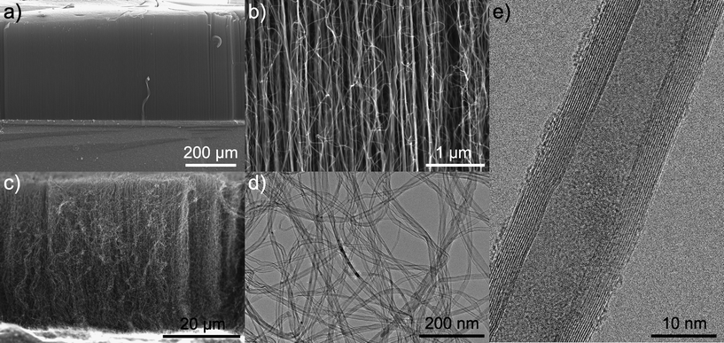 | ||
| Fig. 3 SEM images of nanotubes grown on Al2O3/SiO2/Si (a and b). SEM, TEM and HRTEM images of nanotubes grown on SiO2/Si (c–e). | ||
Raman spectra of the as-grown vertically aligned CNTs permitted the evaluation of their purity and degree of graphitization. The spectra exhibit two main bands centered around 1340 cm−1 (D band) and 1575 cm−1 (G band), characteristics of MWCNTs (Fig. 4).28–30 The strong G band corresponds to the stretching mode of the C–C bond in the graphitic plane and demonstrates the presence of crystalline graphitic carbon. On the other hand, the D band originates from defects and amorphous carbon. The intensity ratio (ID/IG) is indicative of the degree of crystallinity of the CNTs. A low intensity ratio corresponds to a superior degree of graphitization and a small amount of defects and amorphous carbon. The ID/IG ratios estimated from Raman studies are ID/IG = 0.70 and 1.04 for the VACNTs grown onto SiO2/Si and Al2O3/SiO2/Si wafers, respectively.
 | ||
| Fig. 4 Raman spectra of the vertically aligned CNTs obtained from the iron catalyst deposited onto SiO2/Si (dashed line) and Al2O3/SiO2/Si (full line) wafers. | ||
These results confirm the structural quality of the VACNTs. For comparison similar ID/IG ratios are obtained for CVD grown VACNTs from iron-based catalysts deposited by state of the art and more complex physical vapor deposition techniques.14,31–33
In order to demonstrate the versatility of the synthesis of the catalyst layer, CNTs were also grown onto non-planar surfaces. As demonstrated above the microwave-assisted nonaqueous sol–gel route permitted the homogeneous deposition of iron oxide nanoparticles onto silica spheres (cf.Fig. 1e and f). These iron oxide-coated silica spheres were deposited on a silicon wafer by spin coating prior to processing in the CVD reactor for CNTs growth, similarly to the planar substrates. After CVD growth for 10 or 30 s a black coloration could be noticed indicating the formation of carbon materials onto these nanostructured substrates. SEM revealed the formation of CNTs arising from the silica particles (Fig. 5a and b). The CNTs do not grow vertically oriented with respect to the substrate and present a curly morphology. This is attributed to the suppression of the steric interaction which in planar substrates promotes the vertical alignment when CNTs are grown from planar substrates. Nevertheless, wool ball and urchin-like heterostructures proved to be of a great interest for applications in composite materials.34
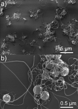 | ||
| Fig. 5 SEM images of CNTs grown onto SiO2 spheres for 10 (a) and 30 s (b). | ||
Conclusions
In this communication, it was demonstrated that the microwave-assisted nonaqueous sol–gel route is a versatile approach for the deposition of iron-based catalysts for CNTs growth. It was shown that the deposition of iron oxide nanoparticles can be accomplished onto various substrates including silica and aluminium oxide-terminated silicon wafers and colloidal silica nanoparticles. On one hand, the growth of high quality vertically aligned CNTs was demonstrated onto planar substrates. On the other hand, novel nanostructures were obtained when CNTs were grown from catalyst nanoparticles deposited onto colloidal silica spheres. Finally, this work paves the way for the utilization of unusual supports for CNTs growth and will certainly lead to the development of novel CNT-based devices.Acknowledgements
Seung-Ho Yu from Seoul National University is acknowledged for XPS measurements and fruitful discussion, Igor Bdikin and A. J. S. Fernandes from the University of Aveiro for AFM and Raman spectra, respectively. This work was partially supported by the WCU (World Class University) program through the National Research Foundation (NRF) of Korea funded by the Ministry of Education, Science and Technology (R31-10013) and FCT projects (PTDC/CTM/098361/2008), (SFRH/BD/71453/2010), and (SFRH/BD/45177/2008).Notes and references
- R. H. Baughman, A. A. Zakhidov and W. A. de Heer, Science, 2002, 297, 787–792 CrossRef CAS.
- H. Chen, A. Roy, J.-B. Baek, L. Zhu, J. Qu and L. Dai, Mater. Sci. Eng., R, 2010, 70, 63–91 CrossRef.
- C. Mattevi, C. T. Wirth, S. Hofmann, R. Blume, M. Cantoro, C. Ducati, C. Cepek, A. Knop-Gericke, S. Milne, C. Castellarin-Cudia, S. Dolafi, A. Goldoni, R. Schloegl and J. Robertson, J. Phys. Chem. C, 2008, 112, 12207–12213 CrossRef CAS.
- R. Philippe, A. Morançais, M. Corrias, B. Caussat, Y. Kihn, P. Kalck, D. Plee, P. Gaillard, D. Bernard and P. Serp, Chem. Vap. Deposition, 2007, 13, 447–457 CrossRef CAS.
- R. Philippe, B. Caussat, A. Falqui, Y. Kihn, P. Kalck, S. Bordère, D. Plee, P. Gaillard, D. Bernard and P. Serp, J. Catal., 2009, 263, 345–358 CrossRef CAS.
- S. Banerjee, T. Hemraj-Benny and S. S. Wong, Adv. Mater., 2005, 17, 17–29 CrossRef CAS.
- G. D. Nessim, Nanoscale, 2010, 2, 1306–1323 RSC.
- A. Hirsch., Angew. Chem., Int. Ed., 2002, 41, 1853–1859 CrossRef CAS.
- K. J. MacKenzie, O. M. Dunens and A. T. Harris, Ind. Eng. Chem. Res., 2010, 49, 5323–5338 CrossRef CAS.
- B. Zhao, D. N. Futaba, S. Yasuda, M. Akoshima, T. Yamada and K. Hata, ACS Nano, 2008, 3, 108–114.
- A. Gohier, C. P. Ewels, T. M. Minea and M. A. Djouadi, Carbon, 2008, 46, 1331–1338 CrossRef CAS.
- K. B. K. Teo, C. Singh, M. Chhowalla and W. I. Milne, Encycl. Nanosci. Nanotechnol., 2003, X, 1–22 Search PubMed.
- A. V. Melechko, V. I. Merkulov, T. E. McKnight, M. A. Guillorn, K. L. Klein, D. H. Lowndes and M. L. Simpson, J. Appl. Phys., 2005, 97, 041301–041339 CrossRef.
- S. Chakrabarti, H. Kume, L. Pan, T. Nagasaka and Y. Nakayama, J. Phys. Chem. C, 2007, 111, 1929–1934 CrossRef.
- R. G. Villoria, S. L. Figueredo, A. J. Hart, S. A. Steiner, A. H. Slocum and B. L. Wardle, Nanotechnology, 2009, 20, 405611 CrossRef.
- S. Esconjauregui, M. Fouquet, B. C. Bayer, S. Eslava, S. Khachadorian, S. Hofmann and J. Robertson, J. Appl. Phys., 2011, 109, 044303–044307 CrossRef.
- M. Felisberto, L. Sacco, I. Mondragon, G. H. Rubiolo, R. J. Candal and S. Goyanes, Mater. Lett., 2010, 64, 2188–2190 CrossRef CAS.
- N. Pinna and M. Niederberger, Angew. Chem., Int. Ed., 2008, 47, 5292–5304 CrossRef CAS.
- N. Pinna, J. Mater. Chem., 2007, 17, 2769–2774 RSC.
- M. Niederberger and N. Pinna, Metal Oxide Nanoparticles in Organic Solvents, Springer, London, 2009 Search PubMed.
- I. Bilecka, I. Djerdj and M. Niederberger, Chem. Commun., 2008, 886–888 RSC.
- I. Bilecka and M. Niederberger, Nanoscale, 2010, 2, 1358–1374 RSC.
- I. Bilecka, M. Kubli, E. Amstad and M. Niederberger, J. Sol-Gel Sci. Technol., 2011, 57, 313–322 CrossRef CAS.
- W. Stöber, A. Fink and E. Bohn, J. Colloid Interface Sci., 1968, 26, 62–69 CrossRef.
- N. Pinna, S. Grancharov, P. Beato, P. Bonville, M. Antonietti and M. Niederberger, Chem. Mater., 2005, 17, 3044–3049 CrossRef CAS.
- M. Niederberger and G. Garnweitner, Chem.–Eur. J., 2006, 12, 7282–7302 CrossRef CAS.
- S. Baek, S.-H. Yu, S.-K. Park, A. Pucci, C. Marichy, D.-C. Lee, Y.-E. Sung, T. Hyeon, Y. Piao and N. Pinna, RSC Adv., 2011 10.1039/c1ra00797a.
- F. Tuinstra and J. L. Koenig, Raman Spectrum of Graphite, AIP, 1970 Search PubMed.
- A. M. Rao, A. Jorio, M. A. Pimenta, M. S. S. Dantas, R. Saito, G. Dresselhaus and M. S. Dresselhaus, Phys. Rev. Lett., 2000, 84, 1820 CrossRef CAS.
- M. S. Dresselhaus, G. Dresselhaus, R. Saito and A. Jorio, Phys. Rep., 2005, 409, 47–99 CrossRef.
- B. H. Choi, H. Yoo, Y. B. Kim and J. H. Lee, Microelectron. Eng., 2010, 87, 1500–1505 CrossRef CAS.
- T. de los Arcos, M. G. Garnier, P. Oelhafen, D. Mathys, J. W. Seo, C. Domingo, J. V. Garci-Ramos and S. Sanchez-Cortes, Carbon, 2004, 42, 187–190 CrossRef CAS.
- V. I. Alexiadis and X. E. Verykios, Mater. Chem. Phys., 2009, 117, 528–535 CrossRef CAS.
- X. H. Nguyen, Y. B. Lee, C. H. Lee and D.-S. Lim, Carbon, 2010, 48, 2910–2916 CrossRef CAS.
Footnote |
| † Electronic supplementary information (ESI) available: Fe 2p XPS spectra and high resolution version of Fig. 1–3 and 5. See DOI: 10.1039/c1ce06130e |
| This journal is © The Royal Society of Chemistry 2012 |