A novel class of nonlinear optical materials based on host–guest composites: zeolites as inorganic crystalline hosts
Hyun Sung
Kim
,
Tung Cao Thanh
Pham
and
Kyung Byung
Yoon
*
Korea Centre for Artificial Photosynthesis, Centre for Microcrystal Assembly, Centre for Nanomaterials, Department of Chemistry, Sogang University, Seoul-121-742, Korea. E-mail: yoonkb@sogang.ac.kr; Fax: +82-2-706-4269
First published on 20th March 2012
Abstract
The demand for nonlinear optical (NLO) materials with exceptional NLO properties is very large, and hence the search for such materials should be continued not only to enhance their functions in current applications but also to help expedite the materialization of photonics in which photons instead of electrons are used for signal processing, transmission, and storage. This article summarizes the preparation, characteristics, and the future perspectives of novel second order nonlinear optical (2NLO) materials prepared by orientation-controlled incorporation of 2NLO molecules into zeolite channels and third order nonlinear optical (3NLO) materials prepared by compartmentalization of very small (<1.3 nm) PbS QDs within zeolite nanopores under different environments, and the novel chemistry newly unveiled during the preparation of novel zeolite based NLO materials.
 Hyun Sung Kim | Hyun Sung Kim is currently Assistant Professor in Center for Nanomaterials in Sogang University (Korea). He received BS (1998), MS (2003), and PhD (2007) in chemistry from Sogang University (supervisor: Prof. Kyung Byung Yoon) and was a Postdoctoral Fellow at Northwestern University. His main research interests include: synthesis and application of porous material and membrane in nonlinear optics, solar energy conversion and molecular separation. |
 Tung Cao Thanh Pham | Tung Cao Thanh Pham received BS degree in 1999 and MS degree in 2003 from the Department of Chemistry, University of Natural Sciences—Ho Chi Minh City National University (Vietnam). From 2000 to 2006 he worked at Institute of Chemical Technology, Vietnamese Academy of Science and Technology. He obtained his PhD degree in 2011 in chemistry from Sogang University (supervisor: Prof. Kyung Byung Yoon) where he is continuing his research as a postdoctoral fellow. His research field is synthesis of oriented zeolite film for NLO materials and molecule sieve membrane applications. |
 Kyung Byung Yoon | Kyung Byung Yoon received his BS in 1979 from the Department of Chemistry, Seoul National University. In 1981, he obtained his MS from the Department of Chemistry, Korea Advanced Institute of Science and Technology (KAIST), Seoul. From 1981 to 1984 he was employed by Chon Engineering Co. LTD, Seoul, Korea. In 1989, he earned his PhD degree from the Department of Chemistry, University of Houston. He has been an Assistant (1989), Associate (1993) and Full Professor (1998) in Sogang University. He also served as the Dean of the College of Natural Science in the period of 2010–2011. He is currently the Director of the Korea Center for Artificial Photosynthesis (KCAP) located in Sogang University. His current research interests are in the areas of artificial photosynthesis, nonlinear optical zeolite films, synthesis of novel zeolites, organization of nano and micro building blocks, preparation and application of semiconductor quantum dots in zeolites. |
1. Introduction
1.1. General background
The production of new light beams whose amplitudes, frequencies, and phases are altered from the incident laser beam by passing it through dielectric media is one of the fascinating features of the nonlinear optical (NLO) phenomenon.1–4 This phenomenon arises from light-induced polarization of the nonlinear optically active components or bulk materials by the strong oscillating electric fields of the laser beam. Here, the nonlinear optically active components such as molecules or particles dispersed in inert matrices or the integrated nonlinear optically active bulk materials are called NLO materials.In the case when a molecule is nonlinear optically active, the light-induced polarization pd in the molecule is described as a function of the electric field vector (E) as described in eqn (1),
| pd = p0 + αE + βEE + γEEE + ⋯ | (1) |
In the case when a bulk dielectric medium or material is nonlinear optically active, the light-induced polarization Pd of the dielectric medium is described as a function of the electric field vector (E) as described in eqn (2),
| Pd = P0 + χ(1)E + χ(2)EE + χ(3)EEE + ⋯ | (2) |
In the above equations, due to spatial symmetry restrictions, the quadratic terms βEE and χ(2)EE become nonzero when there exist net dipole moments in the molecules and bulk materials, respectively. In such cases, the characteristic 2nd-order NLO (2NLO) phenomena are observed, and such molecules and bulk materials are specifically called 2NLO materials. Unlike 2NLO activity, a 3rd-order NLO (3NLO) process occurs from any material regardless of the presence of a net dipole moment in the medium. In this respect all materials can be regarded in principle as 3NLO materials but the question is how high their 3rd-order hyperpolarizabilities or susceptibilities are. In this respect, those materials having large 3rd-order hyperpolarizabilities and susceptibilities are called 3NLO materials.
A 2NLO material generates a second harmonic (2ω) from the incident laser beam with the frequency of ω and shows the electro-optic property. In the case of a bulk 2NLO material, the intensity of 2ω depends on the path length of the laser beam in the dielectric medium. Accordingly, the intrinsic values, namely, tensor components of the quadratic NLO susceptibilities (dmn) are often compared between 2NLO materials to compare their 2NLO activities.
A 3NLO material not only produces the third harmonic (3ω) from the incoming laser beam but also reversibly changes its refractive index (n) and absorption coefficient (α) as the intensity of the incident beam (I) changes according to eqn (3) and (4),
| n = no + n2I | (3) |
| α = αo + α2I | (4) |
| [χ(3)]R = 2no2εocn2 | (5) |
| [χ(3)]i = [no2εoc2α2]/ω | (6) |
After the first discovery of the 2NLO phenomenon from a quartz crystal in 1961,1 innumerable numbers of 2NLO and 3NLO materials have been developed5 and some of them are currently widely used as key materials in various fields which require light frequency alteration, light signal amplification, and modulation of intensity or phase of the light, namely, as key materials for optical communication, optical switching, laser components, waveguides, optical limiters, saturable absorbers, and IR detectors for medical and military applications. However, the demand for NLO materials with exceptional NLO properties is still very large, and hence the search for such materials should be continued not only to enhance their functions in current applications but also to help expedite the materialization of photonics in which photons instead of electrons are used for signal processing, transmission, and storage.
1.2. 2NLO materials
Various 2NLO ionic crystals such as potassium dihydrogen phosphate (KDP = KH2PO4), lithium niobate (LiNbO3), barium sodium niobate (Ba2NaNb5O15), β-barium borate (BBO = BaB2O4), and so on have been developed and are currently widely used. However, the growths of these inorganic crystals are time consuming, often requiring 1–8 weeks, and they are usually hygroscopic, requiring humidity controlled environments. Most of all, their dmn values are not high enough (1–18 pm V−1) to be used in miniature integrated photonic devices.In fact, there are a large number of organic, inorganic, and organometallic molecules having large β values,6 which can be assembled or organized into 2NLO materials with very high sensitivities. The first methodology for their organization has been the crystallization into 2NLO materials. However, the dipolar molecules have an intrinsic tendency to crystallize into centrosymmetric crystals, having a zero overall dipole moment. Accordingly, there have been great efforts to develop methods to crystallize them noncentrosymmetrically.7,8 However, the efforts have been of limited success.
The second methodology has been the formation of NLO films on substrates by orientation-controlled layer-by-layer deposition of the dipolar molecules by forming physical,9–13 covalent,14–23 or ionic24 linkages between the neighbouring layers. The physical method is often called Langmuir–Blodgett type layer-by-layer deposition9–13 and the chemical method is often referred to as self-assembled monolayer (SAM) deposition.14–23 The latter is in fact a vague notation because the former (Langmuir–Blodgett) type of layer-by-layer deposition also starts from self-assembly or self-organization of molecules. Regardless of the types of linkage formation, the procedures are highly time-consuming, and the mechanical and thermal stabilities of the obtained thin 2NLO films are poor.
The third methodology has been the incorporation of dipolar molecules into polymer matrices by physically blending or by covalently anchoring the dipolar molecules onto the side chains of polymer backbones.25–31 This methodology can be named as a host–guest composite formation methodology. In the initially prepared composites, the incorporated dipolar molecules are randomly oriented within the polymer matrices. Therefore electrical poling of the 2NLO molecules is conducted to orient a large portion of the 2NLO molecules into a uniform direction.32 For this, strong dc electrical fields are often applied across the 2NLO molecule-polymer composite films while keeping the temperature of the polymer hosts above the glass transition temperatures. However, the gradual orientation relaxation or so called ‘depoling’ under the application conditions has been the key problem, due to temperature increases in the 2NLO polymer matrices under the operating conditions. Thus, poor temporal stabilities have been the problem. As a means to obtain high temperature temporal stability, polyimide and poly(imide-amide) have been introduced as the polymer hosts because their glass transition temperatures are high.33 For instance, a relatively high temporal stability (92% after 100 h operation) was recently demonstrated at 200 °C.33 However, the thermal instability of many 2NLO molecules at high glass transition temperatures limits the variation of the types of 2NLO molecules.
As a possible means to overcome the demerits arising from the use of polymer matrices as hosts, zeolites and the related mesoporous materials have been examined as the alternative hosts. Stucky and co-workers first discovered that para-nitroaniline (PNA), 2-methyl-4-nitroaniline (MNA), and 2-amino-4-nitropyridine (Fig. 1) readily enter the straight channels of AlPO4-5 (Fig. 2), and the 2NLO molecule-incorporating AlPO4-5 powders generate 2ω with the intensity far exceeding that of quartz powders.34,35 Marlow, Caro, and their co-workers revealed that the above second harmonic generating (SHG) activity arises as a result of the spontaneous inclusion of PNA into the channels of AlPO4-5 with the nitro group first caused by the intrinsically higher affinity of the AlPO4-5 channels to the nitro than to the amino group.36 Because the sizes of the crystals far exceed (such as 130 μm) the wavelength of the incident laser beam (1.064 μm), the polarization reversal that occurs at the centre of each crystal does not affect the overall SHG activities of the PNA-loaded AlPO4-5 crystals. Other 2NLO molecules such as 4-nitro-N,N-dimethylaniline37 and (dimethylamino)-benzonitrile38 (Fig. 1) have been shown to enter AlPO4-5 channels with the nitro or nitrile group first. Related research has been conducted on MFI-type zeolites (Fig. 2) such as silicalite-1,39 ZSM-540 and Sb-incorporating silicalite-1.41 Among the above, Qiu and co-workers observed a 2NLO activity from a large PNA-including silicalite-1 crystal (3.0 × 1.5 × 1.5 mm3).39 PNA-loaded mesoporous silica (Fig. 2) also showed a SHG activity.42 PNA has also been included into all silica ZSM-12. However, the PNA-loaded all silica ZSM-12 does not show a 2NLO activity because the overall symmetry of the host–guest composite was centrosymmetric.43
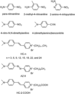 | ||
| Fig. 1 Structures of 2NLO molecules that have been incorporated into the zeolite host. | ||
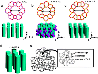 | ||
| Fig. 2 Structures and pore sizes of AlPO4-5 (a), MFI-type zeolite: ZSM-5 or silicalite-1 (b), ZSM-12 (c), MCM-41 (d), and zeolite Y (e). [AlPO4-5: a noncentrosymmetric (P6cc) zeolite analogue having one-dimensional channels with a diameter of 0.8 nm. MFI: a centrosymmetric (Pnma) zeolite having a three-dimensional channel system consisting of straight 0.53 × 0.56 nm channels in one direction and sinusoidal 0.51 × 0.55 nm channels in the other direction perpendicular to the straight channels. ZSM-12: a centrosymmetric (C2/c) silica zeolite having one-dimensional channels with an opening of 0.56 × 0.60 nm. MCM-41: a centrosymmetric (P6mm) mesoporous silica having one-dimensional channels with diameters between 1.5 and 10 nm. Zeolite Y: a centrosymmetric (Fd3m) aluminosilicate zeolite having three-dimensional pore structure with a diameter of pore opening of 0.74 nm. | ||
Thus, the potential of zeolites and the related mesoporous silica as versatile inorganic hosts for preparation of practically viable organic–inorganic composite SHG materials has been demonstrated.34–42 However, the previous studies have been limited to PNA and the analogous 2NLO molecules with relatively low β values (βPNA = ∼35 × 10−30 esu at 1064 nm).44,45 Furthermore, the zeolite hosts have been limited to powders and very small single crystals that bear limited practical applicability. Furthermore, the 2NLO activities of microcrystalline zeolite powders should be measured by the Kurtz and Perry technique,46 which gives qualitative data. Therefore, to develop commercially viable zeolite-molecule host–guest 2NLO materials, methods to incorporate 2NLO molecules with high β values into zeolites in uniform orientations and to prepare optically transparent zeolite films have to be developed.
With this background in mind, by choosing hemicyanine (HC) molecules (β = ∼760 × 10−30 esu at 1064 nm) as prototypical 2NLO molecules and silicalite-1 (Fig. 2b) films as prototypical zeolite films, our group has conducted a series of research aiming at the developments of methods to include HC molecules into silicalite-1 channels in uniform orientations and to prepare transparent zeolite films.47–50 The structures of HC molecules and the related molecule that have been employed by our group are shown in Fig. 1. They are HCs with different alkyl chain lengths (HC-n, where n = 3, 6, 9, 12, 15, 18, 22, and 24), an azo-bridged HC-9 analogue (denoted as AZ-9), and a HC with a propionic acid tail (denoted as HC-2–CO2H). For this, our group has also conducted a series of research aimed at the growth of silicalite-1 films on glass substrates with the straight channels (5.3 × 5.6 Å) uniformly oriented normal to the glass surface. This article summarizes the results and the perspective views for future studies.
1.3. 3NLO materials
Semiconductor quantum dots (QDs) dispersed in dielectric matrices, such as polymer and glass, have received great attention as 3NLO materials.51–65 However, their 3NLO activities have not been high enough for practical applications. There are two types of processes in 3NLO activity: resonant and nonresonant.51In a resonant process, the frequency of the incident beam overlaps with a one- or multiphoton electronic absorption band, and the transient change in α induced by light absorption is responsible for the 3NLO activity. The smallest possible semiconductor QDs with narrow size distributions and high extinction coefficients (e.g. PbS and GaAs) have been expected to give high 3NLO responses.51
In a nonresonant process, the frequency of the incident beam does not overlap with an electronic absorption band. The 3NLO activity then arises from the interaction of the local field of the host–guest complex arising from the difference in n of the host and guest or from the dipole–dipole interaction between the host and guest materials and the oscillating electric field of the incident beam.51 Semiconductor materials with larger sizes have been regarded to be more active because their n and dipole moments increase with increasing size.
With this background in mind, and from the well-established fact that zeolites are excellent hosts for the generation and stabilization of very small semiconductor QDs with sizes smaller than 1.5 nm,66–78 our group has conducted a series of research79,80 aiming at the production of highly active 3NLO materials based on zeolite–QD composite materials. In fact the QDs generated within zeolite pores have been unstable when the QD-incorporating zeolites were exposed to the atmosphere due to moisture imbibition.74–76 In order to solve this problem our group has also conducted a series of research to develop methods to stabilize the generated QDs within zeolite interiors. Parallel with this, we have developed a method to prepare stable zeolite Y films on transparent substrates.80 This article also summarizes these results and the future perspectives.
2. 2NLO silicalite-1 films with hemicyanine as the guest
2.1. Growth of uniformly oriented silicalite-1 films by primary and secondary growths
Initially we prepared silicalite-1 films on glass plates based on the methodology so called primary growth.47 In this method, clean glass plates (with no seed crystals on the surfaces) are simply immersed into a conventional synthesis gel consisting of a silicon source (usually tetraethyl orthosilicate, TEOS), tetrapropylammonium hydroxide (TPAOH), and water, and the hydrothermal reaction was carried out at appropriate temperatures for appropriate period of time, such as 140 °C for 5 h. Under this condition silicalite-1 films readily grow on both sides of the glass plates with the thicknesses of ∼400 nm. The glass plates coated with primarily grown silicalite-1 films on both sides are denoted as (p-SL)/G/(p-SL).As the typical scanning electron microscope (SEM) image (Fig. 3a) shows the obtained silicalite-1 films are b-oriented, in other words, the b-axis of the film (the axis along which the straight channels run) points normal to the substrate plane. The typical side view (Fig. 3b) also confirms this. The b-orientation is further confirmed by the X-ray diffraction pattern (not shown) which shows only the diffraction lines arising from (0 k 0) planes with k = 2, 4, 6, 8, 10, and so on. However, the thickness is not uniform as blue arrows indicate in the top view due to the crystals which grow in the bulk, and subsequently deposit on the primarily grown silicalite-1 film (Fig. 3a). Furthermore there are a-oriented intergrown crystals simultaneously grown on many spots as the red arrows indicate. In fact sinusoidal channels run along the a axis and due to their narrower channel opening (0.51 × 0.54 nm for a sinusoidal channel vs. 0.54 × 0.56 nm for a straight channel) and due to the sinusoidal nature of the channels HC molecules do not readily enter the channels. This is one of the reasons why the number density of the entered molecules in the primarily grown silicaite-1 film per unit area is small as will be discussed in more detail in the later part of this article. Consequently, the numbers of HC molecules entering the silicalite-1 channels were low due to the presence of large number of a-oriented spots on the b-oriented silicalite-1 films. Furthermore, it was impossible to maintain uniform b-orientation of the silicalite-1 films when the hydrothermal reaction was carried out for longer periods of time as a means to increase the thickness of the films (>400 nm) due to the orientation randomization which starts taking place when the film thickness increases beyond 400 nm. The growth of the thinner silicalite-1 films was also impossible because not all areas of the glass plates become covered with the film when the growth was carried out for lesser periods of time.
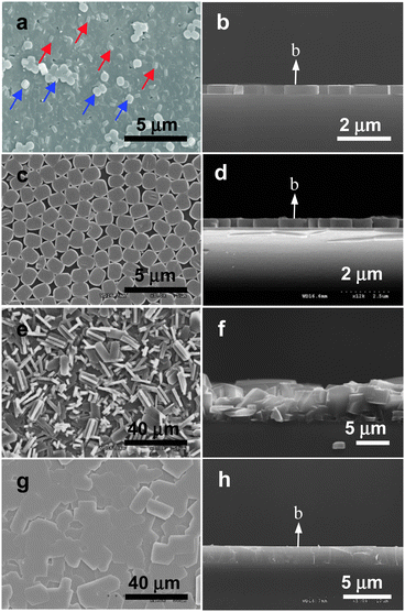 | ||
| Fig. 3 SEM images of a typical primarily grown silicalite-1 film, top (a) and cross sectional (b) views; a monolayer of silicalite-1 crystals assembled on a glass plate, top (c) and cross sectional (d) views; a randomly oriented continuous silicalite-1 film grown from the monolayer by reacting in a gel which uses TPAOH as SDA, top (e) and cross sectional (f) views; a perfect b-oriented continuous silicalite-1 film grown from the monolayer by reacting in a gel which uses TEAOH as SDA, top (g) and cross sectional (h) views. (Adopted from ref. 47 and 50.) | ||
To improve the degree of perfect b-orientation and to acquire the ability to control the thickness of the silicalite-1 films while maintaining the perfect b-orientation, monolayers of b-oriented silicalite-1 crystals were first prepared on glass substrates by rubbing,81 and they were used as the seed crystals for the growth of perfect b-oriented silcalite-1 films on glass plates. The typical top and side view SEM images of a monolayer of silicalite-1 crystals are shown in Fig. 3c and d. However, when the conventional method of secondary growth was conducted, randomly oriented silicalite-1 films are obtained as the typical top and side view SEM images (Fig. 3e and f) show.
Recently, we developed a novel secondary growth method which allows maintenance of perfect b-orientation which was set by the attached seed crystals.50 Thus, as the typical top and side view SEM images (Fig. 3g and h) show, the newly prepared silicalite-1 films by the newly developed secondary growth method show perfect b-orientation in every place of the film. The difference between the conventional and our new methods lies on the fact that in the case of the conventional method TPAOH is used as the structure-directing agent (SDA) while tetraethyl-ammonium hydroxide (TEAOH), tetramethylammonium hydroxide (TBAOH), or tetrabutylammonium hydroxide (TMAOH) is used as SDA.
In the case when TPAOH is used as SDA, autogenesis of silicalite-1 crystals takes place in the bulk. The silicalite-1 crystals produced in the bulk subsequently deposit or adhere randomly onto the silicalite-1 films, and grow further giving rise to orientation randomization of the film. However, when other tetraalkylammonium hydroxide was used as SDA, no autogenesis of the crystals occurs in the bulk. However, the growth of seed crystals deposited on the glass plates continued in the same orientation, giving rise to the production of perfect b-oriented silicalite-1 films. The glass plates coated on both sides with secondarily grown perfect b-oriented silicalite-1 films are denoted as (s-SL)/G/(s-SL).
For the NLO zeolite films to be useful for optical applications, the films should also be optically transparent. We found that the perfect b-oriented films produced by our new method are quite transparent and can be comparable with that of a bare glass plate as shown in Fig. 4. In contrast, the transparencies of randomly oriented silicalite-1 films grown by the conventional secondary growth method were poor.
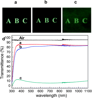 | ||
| Fig. 4 Photographs of a 1 mm thick bare glass plate (a), the same glass plate coated with perfect b-oriented silicalite-1 films on both sides (b), and the same glass plate coated with randomly oriented silicalite-1 films on both sides (c), and the transmittance spectra of air and three glass plates shown above (as indicated). (Adopted from ref. 50.) | ||
2.2. Inclusion of HC-n into silicalite-1 films
Into each vial (25 mL capacity) containing a methanol solution of different HC-n (10 mL, 1 mM) two (p-SL)/G/(p-SL) or (s-SL)/G/(s-SL) plates were added, and the vial was kept at room temperature for a desired period of time from 1 day to 3 weeks. After equilibration, the (p-SL)/G/(p-SL) or (s-SL)/G/(s-SL) plates were removed from the solution, washed with copious amounts of fresh methanol, and dried in air. The included dyes do not come out back to the solution even after keeping them in fresh methanol for 3 days if they once enter the silicalite-1 channels. This shows that the silicalite-1 channel has a very strong affinity toward HC-n dyes regardless of the chain length, indicating that inclusion of HC-n into the silicalite-1 channel is a non-equilibrium, irreversible process in methanol.2.3. Measurements of 2NLO activities
The 2ω intensities (I2ω) of the HC-incorporating (p-SL)/G/(p-SL) or (s-SL)/G/(s-SL) plates were measured using the Maker fringe method82 and the measured intensities were compared with respect to the value of a 3 mm-thick y-cut quartz crystal, a piece of 3 mm thick quartz plate whose plane is perpendicular to its crystalline y-axis. Thus, in this article, relative I2ω (rel-I2ω in %) values are reported and their values compared. A drop of dimethylsulfoxide (DMSO) was dropped onto each side of the HC-incorporating (p-SL)/G/(p-SL) or (s-SL)/G/(s-SL) plates as an index matching fluid, respectively, and each side of silicalite-1 film was covered with a clean bare glass plate. This is necessary to avoid scattering of the incident laser beam caused by the irregular thickness of the silicalite-1 films.The polarity of the fundamental laser beam was adjusted using a half-wave plate before it hit the sample. The electric field vector of the incident beam was either parallel (p-polarization) or perpendicular (s-polarization) to the plane of incidence. Only the p-polarized 2ω beam was made to enter a PMT by using a prism, a 2ω pass filter, and a polarizer. A sample plate was mounted on the rotator coupled to a step motor. The output signals from the photodiode and PMT were detected as a function of an incident angle. The opposite dipole moments of the silicalite-1 films do not cancel each other because the gap (1 mm, Fig. 5a) between the two HC-incorporating films is larger than the wavelength of the incident beam. As a result, Maker fringes appear due to the constructive and destructive interferences between the two 2ω signals arising from the two layers. A typical Maker fringe is shown in Fig. 5b for the case of HC-18-incorporating (p-SL)/G/(p-SL) or (s-SL)/G/(s-SL) films. If only one side of the glass plates is coated with HC-incorporating silicalite-1 film [HC-incorporating (p-SL)/G or (s-SL)/G)] (Fig. 5c) then a broad hump appears as typically shown in Fig. 5d. The fact that the destructive interferences give zero rel-I2ω values in Fig. 5b indicates that the two HC-incorporating silicalite-1 films are identical in terms of thickness, amount of HC-loading, and the degree of uniform orientation of the incorporated HC molecules.
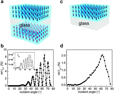 | ||
| Fig. 5 A schematic illustration of a glass plate coated with HC-18-incorporating silicalite-1 films on both sides (a) and its typical Maker fringe obtained from the p-polarized laser beam (b). The corresponding Maker fringe obtained from the s-polarized laser beam is shown in the inset. A schematic illustration of a glass plate coated with HC-18-incorporating silicalite-1 film only one side (c) and its typical Maker fringe obtained from the p-polarized laser beam (d). (Adopted from ref. 47.) | ||
The maximum rel-I2ω is taken as the representative value of each 2NLO film. Usually, the maximum rel-I2ω value is observed at 67°. The 2ω intensities obtained from the p-polarized laser beam are higher than those obtained from the s-polarized beam by more than three orders of magnitude, confirming that the HC molecules are aligned vertically. This already indicates that, unlike the 2NLO molecules imbedded in polymer matrices, the vertical orientation of HC molecules in silicalite-1 films is very high, close to 100%. In this article, only the rel-I2ω values that were obtained from p-polarized laser beams are compared.
2.4. Degree of uniform orientation (DUO)
DUO is defined as the ratio between the HC molecules pointing to the same direction and the total number of HC molecules incorporated into silicalite-1 channels. This is equivalent to the ratio between the experimentally observed d33 value [d33(e)] and the maximum d33 value theoretically calculated assuming that all the incorporated HC molecules are oriented in the same direction [max-d33(t)], namely [d33(e)]/[max-d33(t)].2.5. Orientation-control by hydrophobic–hydrophobic interaction47
Silicalite-1 channels are hydrophobic because the channel walls are made of SiO2 units with no hydroxyl groups. Because of this, when HC-n molecules with varying alkyl chain lengths were used, DUO progressively increases as n increases as shown in Fig. 6a for the case where the primarily grown silicalite-1 film (Fig. 3a) was used. This arises because the tendency of HC-n molecules to enter silicalite-1 channels with the alkyl tail part first increases as the chain length n increases as schematically shown in Fig. 6b. It is important to note here that the hydrophilic centre is localized at the pyridinium part and both 1,4-(dimethylamino)phenylenevinyl and n-alkyl groups are hydrophobic as illustrated in Fig. 6b with HC-6 as an example. Thus, while the probabilities to enter the silicalite-1 channels with the alkyl tail part first and the dimethyl amine part first are 50![[thin space (1/6-em)]](https://www.rsc.org/images/entities/char_2009.gif) :
:![[thin space (1/6-em)]](https://www.rsc.org/images/entities/char_2009.gif) 50 giving rise to DUO of 0 in the case of HC-6, their probabilities of HC-22 are 95
50 giving rise to DUO of 0 in the case of HC-6, their probabilities of HC-22 are 95![[thin space (1/6-em)]](https://www.rsc.org/images/entities/char_2009.gif) :
:![[thin space (1/6-em)]](https://www.rsc.org/images/entities/char_2009.gif) 5 giving rise to DUO of 0.95. This occurs because the degree of hydrophobic–hydrophobic interaction between the alkyl tail and the silicalite-1 channel increases as the alkyl chain length increases. The above result thus demonstrates that the orientations of 2NLO molecules can be controlled to a uniform direction in the zeolite host with this methodology.
5 giving rise to DUO of 0.95. This occurs because the degree of hydrophobic–hydrophobic interaction between the alkyl tail and the silicalite-1 channel increases as the alkyl chain length increases. The above result thus demonstrates that the orientations of 2NLO molecules can be controlled to a uniform direction in the zeolite host with this methodology.
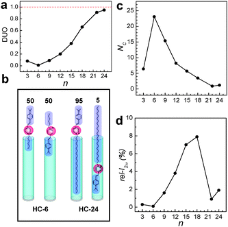 | ||
Fig. 6 The plots of DUO (a) and NC (b) versus n. A schematic illustration of the insertion of HC-6 into silicalite-1 channels with equal probabilities (50![[thin space (1/6-em)]](https://www.rsc.org/images/entities/char_2009.gif) : :![[thin space (1/6-em)]](https://www.rsc.org/images/entities/char_2009.gif) 50) for alkyl tail and head first and the contrasting behaviour of HC-24 which has a much higher probability (95%) to enter the silicalite-1 channels with the hydrophobic tail first than that for the head part first (c). The plot of rel-I2ωversus n (d). (Adopted from ref. 47.) 50) for alkyl tail and head first and the contrasting behaviour of HC-24 which has a much higher probability (95%) to enter the silicalite-1 channels with the hydrophobic tail first than that for the head part first (c). The plot of rel-I2ωversus n (d). (Adopted from ref. 47.) | ||
The problem is that the number of HC-n molecules entering each channel (NC) progressively decreases as n increases (Fig. 6c). For example, in the case of the primarily grown silicalite-1 films, NC decreases from 24 to 1 as n increases from 6 to 22. As a result, the rel-I2ω value gradually increases from 0.3 to 7.9% as n increases from 3 to 18 and subsequently decreased to 1.9 as n further increases to 24 (Fig. 6d).
When HC-n molecules are allowed to contact with the secondarily grown perfect b-oriented siliclaite-1 films, NC increases significantly, not only when the film thickness is higher (2.4–3.0 μm) than that of the primarily grown film (400 nm) but also when the film thickness is smaller (130 nm) (Fig. 7a). Furthermore, unlike the case into the primarily grown silicalite-1 film, NC progressively increased with increasing n from 6 to 15 and decreased as n further increases to 24. Thus, in the case of HC-15, while NC was 3.5 in the case of the primarily grown silicalite-1, it became 71.9. These results indicate that the qualities of the perfect b-oriented silicalite-1 films are higher than those of the primarily grown silicalite-1 channels, and the channels of the perfect b oriented silicalite-1 channels are more hydrophobic than those of the primarily grown silicalite-1 films. Consistent with the larger NC values, rel-I2ω values increased significantly (Fig. 7b). Thus, with the HC-15-incorporating 3.0 μm thick silicalite-1 film, the measured rel-I2ω was 174.5 which is 22 times larger than the largest value observed from the primarily grown silicalite-1 film with HC-18.
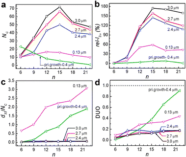 | ||
| Fig. 7 Plots of the number of HC-n molecules incorporated into a single channel (NC) of the silicalite-1 film versus the alkyl chain length n of the HC-n for the perfect b-oriented silicalite-1 films with different thickness (as indicated) and the primarily grown 400 nm thick silicalite-1 film (a). Plots of the relative second harmonic intensity (rel-I2ω) of the HC-n-incorporating SL films (of indicated thickness) with respect to a reference (3 mm-thick y cut quartz) versus the alkyl chain length n of the HC-n (b). Plots of the d33 values normalized by the incorporated number of HC molecules (NC) of the HC-n-incorporating SL films versus the alkyl chain length n of the HC-n (c). Plots of the DUO values of the HC-n-incorporating SL films versus the alkyl chain length n of the HC-n (d). (Adopted from ref. 50.) | ||
The problem is that d33 of the HC-15-incorporating 3.0 μm thick secondarily grown silicalite-1 film (HC-18@sec-silicalite-1: 2.68 pm V−1) is smaller than that of the HC-18-incorporating primarily grown silicalite-1 film (HC-18@prim-silicalite-1: 5.30 pm V−1) (Table 1). The plots of the d33 values with respect to the NC values (Fig. 7c) show that in the cases of secondarily grown perfect b-oriented thick (2.4–3.0 μm) silicalite-1 films the normalized d33 values are much smaller than that of the primarily grown silicalite-1 film. Accordingly, the corresponding DUO values are lower than that of primarily grown silicalite-1 films for each HC-n, especially as n increases (Fig. 7d). These results indicate that the selectivity to a specific orientation decreases upon substituting the primarily grown silicalite-1 film to the secondarily grown perfect b-oriented silicalite-1 films. So there should be research efforts to increase DUO during incorporation of HC-n into the secondarily grown perfect b-oriented silicalite-1 films.
| Materials | d nm /pm V−1 | Ref. |
|---|---|---|
| Quartz, SiO2 | 0.36 (d11) | 5 |
| LiNbO3, | 2.76 (d22) | 5 |
| KTP, KTiOPO4 | 6.5 (d31) | 5 |
| 5.0 (d32) | ||
| 13.7 (d33) | ||
| 2-Cyclooctylamino-5-nitropyridine (COANP) | 10.0 (d33) | 5 |
| KDP, KH2PO4 | 0.39 (d36) | 5 |
| Ba2NaNb5O15 | 12.8 (d24) | 5 |
| −17.6 (d33) | ||
| BBO, β-BaB2O4 | 16.0 (d22) | 5 |
| HC-15@sec-silicalite-1, 0.13 μm | 35.4 (d33) | 50 |
| HC-15@sec-silicalite-1, 3.0 μm | 2.68 (d33) | 50 |
| HC-18@prim-silicalite-1, 0.4 μm | 5.30 (d33) | 47 |
In any case, the d33 value of the HC-15-incorporating secondarily grown 0.13 μm thick silicalite-1 film (HC-15@sec-silicalite-1, 0.13 μm) was 35.4 pm V−1, which is comparatively much higher than those of the commercially available 2NLO materials listed in Table 1.5 This indicates the great potential of HC-incorporating silicalite-1 films to be developed into commercially viable 2NLO materials.
2.6. Inclusion in the photoexcited state48
The above results show that HC-n dyes with n ≥ 18 have a great tendency to enter the primarily grown silicalite-1 channels with the alkyl chain first (Fig. 6a), giving rise to high DUO values (>0.67). However, the DUO values for shorter-chain HC molecules are much smaller. Theoretical studies have shown that, in the excited state, a substantial amount of positive charge density develops at the dimethylamine terminal whilst almost all of the positive charge density disappears from the pyridinium ring83 as illustrated in Fig. 8a for the case of HC-9. This leads to the shift of the hydrophilic part from the centre to the very end of the molecule. Therefore, the probability of the photoexcited HC-9 (HC-9*) to enter the channels with the alkyl tail part first increases, as if it became a longer chain HC.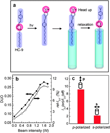 | ||
| Fig. 8 A schematic illustration of the shift of the hydrophilic part (red) to the very end of the head part in the photoexcited state, and the subsequent insertion into silicalite-1 channels with the tail part first (a). Plots of the DUO and rel-I2ω (in %) with respect to the laser beam intensity (b) and the effect of the beam polarization direction (p or s) on the I2ω (on) to I2ω (off) ratio (c). (Adopted from ref. 48.) | ||
Indeed, the rel-I2ω value almost linearly increased from 1.5 to 10% upon increasing the laser power from 0.0 to 1.6 W and then slightly decreased upon further increasing the power to 2.0 W (Fig. 8b). For this experiment a line-polarized (p- or s-polarized) laser beam (cw, 488 nm, beam size = 3 mm) generated from an Ar+-ion laser was irradiated onto the silicalite-1 film so that the oscillation direction of the p-polarized laser beam is aligned parallel to the channel direction of the silicalite-1 film and the oscillation direction of the s-polarized laser beam is aligned perpendicular to the channel direction. Since the molar extinction coefficient of HC-9 at 488 nm is 42![[thin space (1/6-em)]](https://www.rsc.org/images/entities/char_2009.gif) 570 M−1 cm−1, irradiation of HC-9 molecules with the laser beam ensures photoexcitation of the molecules.
570 M−1 cm−1, irradiation of HC-9 molecules with the laser beam ensures photoexcitation of the molecules.
Thus DUO increased almost linearly from 0.08 to 0.27 (a ∼3.4-fold increase) upon increasing the laser power from 0.0 to 1.6 W (Fig. 8b). Calculation shows that 1.25 molecules out of 6 molecules which enter each channel with the dimethylamine side part first in the dark change orientation to the alkyl side upon irradiation at 1.6 W, a 21% increase. Comparison with the DUOs of HC-12 (0.2) and HC-15 (0.38) in the dark suggests that HC-9* behaves like HC-13.
The ratio of rel-I2ω with light on with respect to that with light off [rel-I2ω(on)/rel-I2ω(off)] is 9.2 and 2.0 for p- and s-polarization direction, respectively (Fig. 8c). This indicates that those molecules that are oriented parallel to the channel direction in the vicinity of the silicalite-1 film mostly enter the channels in the excited state (Fig. 8a). This result opens new areas of research on the achievement of higher DUOs by photoexcitation and the study of its effect on the dynamics and kinetics of molecular diffusion at the solution–zeolite interfaces. In fact, this work demonstrates for the first time the inclusion of molecules into zeolite channels in the photoexcited state.48
2.7. Orientation control by ion pairing of the carboxylate tail with a bulky cation49
In the case of HC-n insertion into primarily grown silicalite-1 films, NC increases upon decreasing n. However, its DUO decreases as well. In this respect, an attempt to increase DUO for short chain HC-n molecules has been made. The idea was to incorporate HC-2–COOH (Fig. 1) into SL channels in an aqueous solution in the presence of tetrabutylammonium hydroxide (TBAOH), which leads to a ∼16-fold increase in rel-I2ω.The values of HC-2–COOH-incorporating silicalite-1 films prepared from the solutions of NaOH and NH4OH remain constant at ∼1.0% regardless of the concentrations of NaOH and NH4OH between 0.0 and 3.0 mM (Fig. 9a). Thus, the presence of NaOH or NH4OH does not cause the increase of DUO. In contrast, however, the rel-I2ω value increases from 1.0 to 16.0% as the concentration of TBAOH increases from 0 to 2.0 mM, and reaches a plateau when the concentration exceeds 2.0 mM. It is also important to note that NC values are invariably ∼16 per channel, regardless of the concentrations of TBAOH, NaOH, and NH4OH. Calculation shows that a ∼4-fold increase in DUO occurs in 2.0 mM TBAOH solution. The rel-I2ω values of the primarily grown silicalite-1 films incorporated with HC-3, HC-18, and HC-2–COOH in the absence and presence of TBAOH, respectively, are compared in Fig. 9b.
![Plots of I2ωversus [TBAOH], [NaOH], and [NH4OH], as indicated (a). Comparison of I2ω values of the primarily grown silicalite-1 films incorporating HC-3, HC-18, HC-2–COOH at [TBAOH] of 0.0 and 2.0 mM, respectively (b). A schematic illustration of orientation-controlled insertion of HC-2–COOH into the silicalite-1 channels with the tail first induced by the carboxylate-tetrabutylammonium ion pairing. (Adopted from ref. 49.)](/image/article/2012/CC/c2cc30919j/c2cc30919j-f9.gif) | ||
| Fig. 9 Plots of I2ωversus [TBAOH], [NaOH], and [NH4OH], as indicated (a). Comparison of I2ω values of the primarily grown silicalite-1 films incorporating HC-3, HC-18, HC-2–COOH at [TBAOH] of 0.0 and 2.0 mM, respectively (b). A schematic illustration of orientation-controlled insertion of HC-2–COOH into the silicalite-1 channels with the tail first induced by the carboxylate-tetrabutylammonium ion pairing. (Adopted from ref. 49.) | ||
The remarkable effect of TBAOH arises as follows. Thus, HC-2–COOH and TBAOH undergo acid–base titration leading to the formation of HC-2–COO−TBA+ and H2O (eqn (7)).
| HC-2–COOH + TBAOH = HC-2–COO−TBA+ + H2O | (7) |
Due to TBA+ (kinetic diameter of 8.1 Å), which is larger than the SL channel aperture (5.6 × 5.3 Å), a majority of HC-2–COO−TBA+ ion pairs insert only the anion part (HC-2–COO−) into SL channels with the dimethylamine side pointing to the glass substrate while keeping the cation (TBA+) outside the channel (Fig. 9c). The encapsulated HC-2–COO− then enters the channel after acquiring a proton from water by undergoing the cation metathesis reaction. This leads to the ‘head-down’ orientation of HC-2–COOH in the channels. Indeed, an independent phase measurement study84 revealed that a larger fraction of HC-2–COOH molecules enter the SL channels with dimethylamine side first. Now we have two different orientations of HC molecules in silicalite-1 channels, head-up and head-down (Fig. 10a). The comparison of the maximum rel-I2ω values obtained from four different results is made in Fig. 10b.
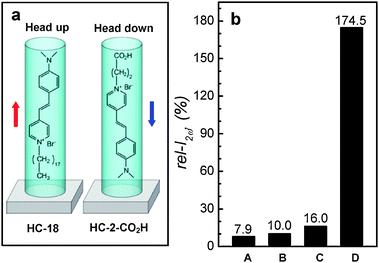 | ||
| Fig. 10 A schematic illustration of the orientations of HC-18 and HC-2–COOH in silicalite-1 channels (a) and the comparison of the maximum rel-I2ω values obtained from different HC molecules: A: HC-18, B: HC-9*, C: HC-2–COOH, and D: HC-15. For silicalite-1 films, primarily grown (A–C) and the secondarily grown perfect b-oriented (D). | ||
2.8. Figure of merit values of HC-15@silicalite-1
For a 2NLO material, the figure of merit (FM) values can be defined as (deff)2/(nω2n2ω), where deff is obtained from eqn (8), and nω and n2ω are refractive indices of the 2NLO material at the beam frequencies of ω and 2ω, respectively. In eqn (8), θ and θ′ represent the angles of incidence and the transmitted beams with respect to the surface normal.deff = d31cos![[thin space (1/6-em)]](https://www.rsc.org/images/entities/char_2009.gif) θ′sin θ′sin![[thin space (1/6-em)]](https://www.rsc.org/images/entities/char_2009.gif) 2θ′ + sin 2θ′ + sin![[thin space (1/6-em)]](https://www.rsc.org/images/entities/char_2009.gif) θ′ [d31cos2 θ′ [d31cos2![[thin space (1/6-em)]](https://www.rsc.org/images/entities/char_2009.gif) θ1 + d33sin2 θ1 + d33sin2![[thin space (1/6-em)]](https://www.rsc.org/images/entities/char_2009.gif) θ′] θ′] | (8) |
| Materials | d eff | n ω | n 2ω | FM | Ref. |
|---|---|---|---|---|---|
| a pm V−1. b Estimated from the fact that silicalite-1 becomes transparent when immersed in DMSO whose refractive index is 1.480. c Estimated from the fact that nω and n2ω values are similar. | |||||
| Quartz, SiO2 | 0.32 | 1.534 | 1.547 | 0.028 | 85 |
| LiNbO3, | −4.52 | 2.232 | 2.233 | 2.76 | 85 |
| KTP, KTiOPO4 | −7.34 | 1.772 | 1.819 | 9.35 | 85 |
| KDP, KH2PO4 | 0.31 | 1.494 | 1.471 | 0.029 | 85 |
| BBO, β-BaB2O4 | 1.11 | 1.657 | 1.554 | 0.29 | 85 |
| HC-18@prim-silicalite-1, 0.4 μm | 2.69 | 1.48b | 1.48c | 2.23 | 47 |
| HC-18@prim-silicalite-1, 0.4 μm | 3.80 | 1.48b | 1.48c | 4.46 | 49 |
| HC-18@prim-silicalite-1, 0.4 μm | 3.70 | 1.48b | 1.48c | 4.23 | 48 |
| HC-15@sec-silicalite-1, 0.13 μm | 18.00 | 1.48b | 1.48c | 99.5 | 50 |
| HC-15@sec-silicalite-1, 3.0 μm | 1.36 | 1.48b | 1.48c | 0.57 | 50 |
3. 3NLO zeolite Y films with PbS quantum dots as the guest
3.1. Preparation of zeolite Y films on ITO glass
Our group discovered that zeolite-Y films grow readily and strongly on indium tin oxide (ITO)-coated glass.79,80 This is one of the important discoveries our group has made in the field of NLO zeolite films and zeolite-based solar cells because zeolite Y films do not readily grow on ordinary glass plates or fused silica plates due to very high basicity of the gel, which gives rise to etching of the glass and fused silica substrates, thereby preventing the film growth on bare glass plates. Even if it appears that zeolite Y films have grown on glass and fused silica plates, they readily peel off the substrates during drying, ion-exchange with other ions, and calcination to remove organic contaminants. However, the zeolite-Y films grown on the surfaces of ITO glass plates remain firmly bonded to the substrates during subsequent processes for the formation of QDs.For the growth of zeolite Y films on ITO glass, nanosized zeolite Y seed crystals are first deposited on ITO glass by spin coating and the subsequent secondary growth is carried out by immersing seeded ITO glass plates into a synthesis gel with the molar composition of 14Na2O:Al2O3:10SiO2:720H2O. The secondary growth reaction is subsequently carried out at 100 °C for 15 h. The average thickness of the resulting zeolite Y films is usually 2 μm (Fig. 11a). After polishing with alumina powder the pristine semitransparent zeolite Y films become quite transparent (Fig. 11c–e). However, polishing gives rise to the decrease in thickness (to 1.5 μm) (Fig. 11b).
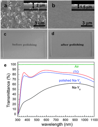 | ||
| Fig. 11 SEM images (top views) of zeolite-Y films grown on ITO glass plates before (a) and after (b) polishing and the corresponding photographs (c and d) and the corresponding transmittance spectra (as indicated) (e). | ||
3.2. Measurements of 3NLO activities
The 3NLO activities of QD-incorporating zeolite Y films were measured using a z-scan method.79,80 In the case of z-scan experiment, the result is affected by the wavelength, pulse width, and the mode of spatial distribution of laser power of each pulse. Our group has obtained nonlinear refraction (n2) and absorption (α2) coefficients of QD-containing zeolite Y films at 532 and 1064 nm, respectively, using mode-locked picosecond laser pulses (pulse width = 50 ps) at two different pulse powers. Comparison of the data was made with those reported in the literature only when their data were obtained under similar experimental conditions.3.3. Types of semiconductor quantum dots and their preparation
The most extensively studied zeolite host for quantum dot incorporation is zeolite Y, and the most extensively studied QDs are CdS and the related transition metal chalcogenide QDs. Therefore, with CdS QDs as the model QDs and zeolite Y as the model zeolite, we have studied formation of CdS QDs in zeolite Y and their behaviours under various conditions in zeolites and the environment surrounding zeolite Y.In zeolite Y, there are two types of cages: sodalite cage and supercage (Fig. 2e and 12). The CdS QDs are prepared in zeolite Y by treating dehydrated Cd2+-exchanged zeolite Y with dry H2S gas (eqn (9)).
| [Cd2+]Y + H2S → [2H+, (CdS)QD]Y | (9) |
In the above, (CdS)QD represents CdS QDs, and 2H+ represents the two H+ ions charge-balancing the two negative (Al) centres in the zeolite Y framework instead of a Cd2+ ion.
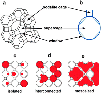 | ||
| Fig. 12 Structures of zeolite Y, its cages, their geometrical representations, and illustration of three types of QDs. | ||
The QDs existing in zeolite Y have been classified into ‘isolated QDs’ existing in supercages, ‘interconnected QDs’ that are formed by interconnection of isolated QDs through the supercage windows, and ‘mesosized QDs’ that exist within the mesosized voids and on the external surfaces of the amorphous aluminosilicate materials that are produced by the framework rupture (Fig. 12). In the case of CdS QDs, the absorption maxima (λmax) of the isolated QDs, interconnected QDs, and mesosized QDs appear in the 200–300, 300–380, and 380–480 nm regions, respectively.75 Conversely, the absorption maxima readily serve as the probes for the identification of the nature of CdS QDs. It is also worthwhile to note that Seff, Heo and co-workers67,86 have demonstrated that CdS QDs can also be formed in the sodalite cages.
3.4. Destructive effect of co-produced H+
Eqn (9) leads to the generation of not only CdS QDs but also H+ ions within the supercages of zeolite Y. Under this circumstance, the environment of the zeolite pores is very acidic, with the pH often less than zero.69,70,80,87 As a result, when the zeolite Y crystals containing both H+ and QDs are exposed to the moist atmosphere, the zeolite framework instantly undergoes rupture, giving rise to the aggregation of QDs into interconnected and mesosized QDs. The degree of aggregation process and the degree of framework rupture depend on the amount of absorbed moisture. Because of this phenomenon, the physicochemical properties of isolated QDs could not be studied under the moist conditions or in aqueous solutions.As a possible means to prevent the H+-induced framework rupture, the surfaces of dry [2H+, (CdS)QD]Y had been coated with octadecyl groups using octadecyltrimethoxysilane (ODM) in a glove box charged with dry argon. The surface-lining octadecyl groups effectively prevent the moisture uptake into the framework, thereby preventing the destructive action of H+.74,79 However, the surface-lining octadecyl groups also prevent ion exchange of the intrazeolite cations with others in aqueous solutions.
3.5. Neutralization of H+ with NH3
It has been known that the intrazeolite H+ ions can be readily neutralized by adding dry NH3 gas.88 By adopting this, CdS QD-incorporating zeolite Y crystals with NH4+ ions as the counter cations were prepared based on eqn (10).| [2H+, (CdS)QD]Y + 2NH3 → [2NH4+, (CdS)QD]Y | (10) |
Unlike [2H+, (CdS)QD]Y, [2NH4+, (CdS)QD]Y remained intact even after exposure to the moist atmosphere for several days. This phenomenon clearly shows that very highly acidic conditions imposed by the high concentration of H+ in the presence of moisture is indeed the cause of the framework rupture. With the above background in mind, [2NH4+, (PbS)QD]Y were prepared in accordance with eqn (11) and (12).
| [Pb2+]Y + H2S → [2H+, (PbS)QD]Y | (11) |
| [2H+, (PbS)QD]Y + 2NH3 → [2NH4+, (PbS)QD]Y | (12) |
3.6. Facile ion exchange without altering QDs80
Remarkably, the NH4+ ions in [2NH4+, (PbS)QD]Y can be readily ion exchanged with various other alkali metal cations MA+ (MA+ = Li+, Na+, K+, and Rb+) (eqn (13)) by aqueous ion exchange.| [2NH4+, (PbS)QD]Y + MA+ → [2MA+, (PbS)QD]Y + 2NH4+ | (13) |
Interestingly, the PbS QDs remain intact under the ion exchange conditions. For example, the diffuse reflectance spectra of [2C+, (PbS)QD]Y (Fig. 13) remain identical regardless of C+ (NH4+, Li+, Na+, K+, and Rb+), indicating that the sizes of QDs do not change during ion exchange. Accordingly, the colours of the films also remain unaltered (maroon; Fig. 13). This is a remarkable fact which provides zeolite scientists a variety of opportunities to explore diverse applications of zeolite-encapsulated QDs with different cation environments. Note that the number of PbS units in the above maroon zeolite Y crystals was 32 per unit cell while the maximum amount that can be introduced into this zeolite is 32.
![Diffuse reflectance spectra of [2C+, (PbS)QD]Y for C+ = NH4+, Li+, Na+, K+, Rb+, and H+ (as indicated) after exposure to the moisture and the corresponding colors (maroon and black for C+ as indicated). (Adopted from ref. 80.)](/image/article/2012/CC/c2cc30919j/c2cc30919j-f13.gif) | ||
| Fig. 13 Diffuse reflectance spectra of [2C+, (PbS)QD]Y for C+ = NH4+, Li+, Na+, K+, Rb+, and H+ (as indicated) after exposure to the moisture and the corresponding colors (maroon and black for C+ as indicated). (Adopted from ref. 80.) | ||
The fact that the absorption tail does not extend beyond 600 nm indicates that all of the PbS QDs exist in the isolated state. This is indeed a very important phenomenon which gave us a unique opportunity to compare the true effect of the cation type on the 3NLO activity of the intrazeolite PbS QDs, which would be impossible if the size and size distribution of the QDs changed simultaneously with changes in the cation type. In contrast, the dry pristine PbS QD-containing zeolite Y film [2H+, (PbS)QD]Y immediately turned black upon exposure to the atmosphere (Fig. 13) as a result of immediate decomposition of the framework and subsequent aggregation of the PbS QDs.
3.7. 3NLO (n2 and α2) values
The n2 and α2 values of ODM–[2H+,(PbS)QD]Y and [2MA+,(PbS)QD]Y measured at 532 and 1064 nm using mode-locked picosecond laser pulses with a pulse width of 50 ps are listed in Table 3. Thus, the magnitudes of n2 and α2 progressively increase with increasing cation size while the signs remain unchanged. The negative n2 values indicate that ODM–[2H+,(PbS)QD]Y and [2MA+,(PbS)QD]Y self-defocus regardless of the type of cation at both wavelengths, and the degree of self-defocusing increases with increasing cation size. The positive and negative α2 values at 532 and 1064 nm, respectively, indicate that the PbS QDs behave as strong excited-state absorbers at 532 nm and optical bleachers at 1064 nm, and the sensitivity increases with increasing size of C+. In fact, this is the first example demonstrating a systematic change in the 3NLO sensitivity of QDs by systematically changing the properties of a dielectric matrix.3.8. Effect of types of cation on 3NLO activity and the explanation
The magnitudes of n2 and α2 increase exponentially with increasing δO (the negative charge density of the framework oxygen) despite the fact that their absorption spectra are the same (Fig. 14). In the semiconductor QD-based resonant 3NLO process, the NLO activity increases with a decrease in the absorption cross section for the transition from the ground state (S0) to the first excited state (S1) during the period of a laser pulse as a result of an increase in the lifetime of a surface-trapped exciton (electron–hole pair) in each QD.51 The increase in 3NLO activity with increasing cation size is attributed to the increase in the lifetime of the surface-bound exciton due to the simultaneous increase in the electron donor strength of the framework oxygen and the electron acceptor strength of the cation, which intimately contacts the PbS QDs (Fig. 15).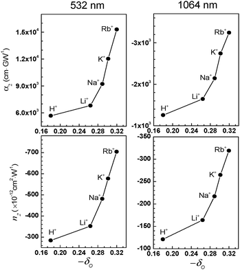 | ||
| Fig. 14 Plots of the α2 (top) and n2 (bottom) values measured at 532 (left) and 1064 nm (right), respectively, with respect to the Sanderson's partial negative charge of oxygen (−δO). (Adopted from ref. 80.) | ||
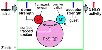 | ||
| Fig. 15 Schematic illustration of the increase in the 3NLO activity of a PbS QD in zeolite Y with increasing cation size. (Adopted from ref. 80.) | ||
Thus, when an exciton is bound to the surface of a QD, the hole (h+) is likely to be positioned at the site that is in intimate contact with the framework oxygen, while the electron (e−) is likely to be positioned at the site that is in intimate contact with a charge-balancing cation. Under this circumstance, the exciton lifetime would be expected to increase when the electron donor strength of the framework oxygen and the electron acceptor strength of the cation increase simultaneously. In zeolites, the simultaneous increase in framework oxygen donor strength and cation acceptor strength toward the guest occurs when the size of the cation increases. Although the former can be easily conceived, the latter is not so intuitive. However, this phenomenon indeed takes place in zeolite Y, as unambiguously demonstrated by the iodide-to-cation charge-transfer band, which red-shifts with increasing size of the cation because of the increase in acceptor strength of the cation as the size of the cation increases.89 This phenomenon occurs because the degree of protrusion of the counter cation toward the supercage increases with increasing cation size (Fig. 16), giving rise to a more intimate donor–acceptor interaction between the guest (iodide or PbS QD) and the cation.
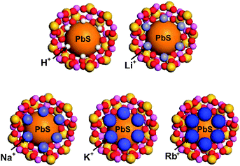 | ||
| Fig. 16 Schematic illustration of PbS-QD containing zeolite Y supercages with different counter cations: H+, Li+, Na+, K+, and Rb+, respectively. | ||
Comparison with the literature values obtained under similar experimental conditions shows that the n2 and α2 values obtained from [2Rb+,(PbS)QD]Y are ∼50 to 900 times higher than the highest values obtained from other QD–dielectric matrix systems51–65 at 532 and 1064 nm, respectively. Such a high sensitivity seems to be arising from the following. The sizes of PbS QDs (<1.5 nm) are smaller than those that have been dispersed in other media (>2.5 nm). The zeolite pores can accommodate a large number of QDs without aggregating them to larger QDs due to the framework rigidity. Third, the interplay of the negatively charged oxide framework and the charge balancing cation greatly increases the lifetime of the produced surface-bound excitons, giving rise to a decrease in the absorption cross section and even providing the opportunity to form biexcitons, whose formation is favoured with decreasing QD size.51
3.9. Figure of merit values of [2C+, (PbS)QD]Y
In general, four types of FM have been defined for 3NLO materials and their values have been compared. They are FM1 [n2Isat/(αoλ)], FM2 (α2λ/n2), FM3 (n2/αo), and FM4 [n2/(ατ)], where Isat is the light intensity at which the change of n saturates and τ is the relaxation time. FM1 represents the maximum nonlinear phase shift obtainable with the lowest loss, FM2 represents the intensity-independent maximum obtainable nonlinear phase shift, FM3 represents the trade-off between the nonlinear response and the attenuation, and FM4 represents the nonlinearity relaxation time. Among these, three FM values (FM1, FM2, and FM3) of [2C+, (PbS)QD]Y are compared with those of commonly encountered 3NLO materials at 532 and 1064 nm, respectively (Table 4). For a 3NLO material to be used as for optical switching FM1 should be much larger than 1 [FM1 ≫ 1] and FM2 should be much smaller than 1 [FM2 ≪ 1].| Materials | 532 nm | 1064 nm | Ref. | ||||
|---|---|---|---|---|---|---|---|
| FM1 | FM2a | FM3b | FM1a | FM2b | FM3 | ||
| a × 10−12 W cm−2. b × 10−14 cm2 W−1 cm−1. c Poly[2,4-hexadiyn-1,6-diol-bis (p-toluene sulfonate)]. d N-(Dimethylaminodnitrophyeny1)acetamide. e Hexadecyltrimethylammonium bis(1,3-dithiole-2-thione-4,5-dithiolato) aurate. f Tetramethylammonium bis(1,3-dithiole-2-thione-4,5-dithiolato) aurate. | |||||||
| [2H+,(PbS)QD]Y | 0.39 | 1.06 | −0.4 | 6.6 | 1.10 | −28 | 80 |
| [2Li+,(PbS)QD]Y | 2.36 | 1.03 | −2.4 | 33.2 | 1.19 | −141 | 80 |
| [2Na+,(PbS)QD]Y | 3.14 | 1.02 | −3.2 | 41.5 | 1.10 | −176 | 80 |
| [2K+,(PbS)QD]Y | 3.83 | 1.11 | −3.9 | 50.7 | 1.10 | −215 | 80 |
| [2Rb+,(PbS)QD]Y | 4.62 | 1.12 | −4.7 | 60.8 | 1.08 | −258 | 80 |
| SiO2 | — | — | — | >103 | ≪1 | 10![[thin space (1/6-em)]](https://www.rsc.org/images/entities/char_2009.gif) 000 000 |
90 |
| RN® (Corning) | — | — | — | 13 | <0.1 | 1300 | 90 |
| PTSc | — | — | — | 40 | 4 | 250 | 90 |
| DANd | — | — | — | >2 | <1 | 20 | 90 |
| GaAs | — | — | — | <2.8 | >17 | — | 90 |
| GaAlAs | — | — | — | 0.9 | — | — | 90 |
| [Ge–Se–As] glass | — | — | — | 1.3 | — | — | 91 |
| [Ge–Se] glass | — | — | — | 0.8 | — | — | 91 |
| [CdSSe] glass | — | — | — | 0.3 | — | — | 85 |
| [MeAu]PMMAe | — | — | — | 6.81 | 0.05 | — | 92 |
| [CtAu]PMMAf | — | — | — | 3.29 | 0.17 | — | 92 |
| [Au]PVP | 50 | 6.6 | — | — | — | — | 93 |
| CdS-dendrimer | ∼10−4 | — | — | — | — | 94 | |
Comparison of the FM values in Table 4 shows that FM1 values of [2C+, (PbS)QD]Y are higher than those of known 3NLO materials except quartz (SiO2) for alkali metal cations at 1064 nm. However, FM2 values are still slightly higher than 1, indicating that [2C+, (PbS)QD]Y are still not eligible to be used for optical switching materials. However, it is interesting to note that the FM2 value decreases as the cation size increases (from 1.19 with Li+ to 1.08 with Rb+). This phenomenon indicates that a further increase in cation size to Cs+ may lead to the 3NLO material which could be used as the optical switching material at 1064 nm.
The corresponding FM1 values at 532 nm are much smaller than those at 1064 nm and the FM2 value increases with increasing cation size. This indicates that [2C+, (PbS)QD]Y are not eligible as the optical switching materials also at 532 nm. The FM3 values of [2C+, (PbS)QD]Y at 1064 nm are much smaller than those of SiO2 and Corning glass RN®.
4. Summary and future perspectives
This article summarizes the preparation and the characteristics of novel 2NLO and 3NLO host–guest materials comprised of silicalite-1 films and HC-series 2NLO molecules for 2NLO materials and zeolite Y films with various counter cations and PbS QDs for 3NLO materials.In the case of 2NLO materials, the key points are how to increase NC, the number of incorporated HC molecules per channel of the silicalite-1 films and how to incorporate them into the channels in uniform orientations. For the latter, two strategies have been demonstrated, the hydrophobic interaction between the long alkyl tail part of HC and the hydrophobic silicalite-1 channel and the formation of ion pair with the carboxylate anion tail and the bulky tetra-n-butylammonium cation, which is size excluded by the channel aperture. The former leads to the insertion of HC into the silicalite-1 channels with the alkyl tail first and the latter leads to the insertion of HC into the silicalite-1 channels with the dimethyl aniline head first. In the case of short alkyl chain HC molecules the degrees of uniform orientation (DUO) of the molecules in the silicaite-1 channels are very poor, approaching zero. However when they enter the silicalite-1 channels in the photoexcited state, their tendency to enter the silicalite-1 channels with the short alkyl chains first increases dramatically. This is because the positive charge localized in the pyridinium centre moves to the very end of the head part, giving rise to a net increase in the length of the hydrophobic part.
The methods to prepare silicalite-1 films sensitively affect NC and DUO. Although the NC values of long alkyl tail HC molecules in the primarily grown silicalite-1films are much lower than those of the secondarily grown perfect b-oriented silicalite-1 films, their DUO values are higher than those of the secondarily grown perfect b-oriented silicalite-1 films. To be able to apply HC-incorporating silicaite-1 films for commercial purposes, the methods to increase NC values and the DUO should be further developed. At the same time, the methods to increase the thickness of perfect b-oriented silicalite-1 films to the mm scale have to be developed.
In the case of 3NLO materials, PbS QD containing zeolite Y films grown on ITO-coated glass plates were studied. Highest n2 and α2 values were observed from [2Rb+,(PbS)QD]Y and the values are ∼50 to 900 times higher than the highest values obtained from other QD–dielectric matrix systems51–65 at 532 and 1064 nm, respectively. The very small sizes of PbS QDs (<1.5 nm), prevention of their aggregation by tight compartmentalization of the QDs, and large increases of the lifetime of the produced surface-bound excitons by interplay of the negatively charged oxide framework and the charge balancing cation seemed to be responsible for the high 3NLO activities. Since there are many different types of QDs and many different types of zeolites having different pore sizes, pore shapes, pore networking, framework compositions, and cations, the development of 3NLO materials with much higher sensitivities operable at various wavelengths is just a matter of time.
Overall, the zeolite host–NLO guest composite materials form a novel class of NLO host–guest materials and they show great potential to be used for commercial applications in the near future. Moreover, the efforts to control orientations of the 2NLO molecules at the time of their inclusion into the narrow subnanometre scale channels and to increase their included number offer us ample opportunities to develop new areas of rich chemistry.
Acknowledgements
We thank the Korea Center for Artificial Photosynthesis (KCAP) located in Sogang University funded by MEST through NRF-2011-C1AAA001-2011-0030278.We thank Jiyun Lee for providing us the illustrative figures. H.S.K. also thanks the Internal Research Grant (200910017) of Sogang University.Notes and references
- P. A. Franken, A. E. Hill, C. W. Peters and G. Weinreich, Phys. Rev. Lett., 1961, 7, 118 CrossRef.
- R. W. Boyd, Nonlinear Optics, Academic Press, San Diego, 3rd edn, 2008 Search PubMed.
- Y. R. Shen, The Principles of Nonlinear Optics, New York, Wiley-Interscience, 2003 Search PubMed.
- R. L. Sutherland, Handbook of Nonlinear Optics, Marcel Dekker, 1992 Search PubMed.
- M. Bass, Handbook Of Optics, Optical Properties Of Materials, Nonlinear Optics, Quantum Optics [e-book], McGraw-Hill Professional, 2010, vol. 4 Search PubMed.
- Nonlinear optics of organic molecules and polymers, ed. H. S. Nalwa and S. Myata, CRC, Florida, 1997 Search PubMed.
- C. Wang, T. Zhang and W. Lin, Chem. Rev., 2012, 112, 1084 CrossRef CAS.
- O. R. Evans and W. Lin, Acc. Chem. Res., 2002, 35, 511 CrossRef CAS.
- G. J. Ashwell, R. C. Hargreaves, C. E. Baldwin, G. S. Bahra and C. R. Brown, Nature, 1992, 357, 393 CrossRef CAS.
- H. Schwartz, R. Mazor, V. Khodorkovsky, L. Shapiro, J. T. Klug, E. Kovalev, G. Meshulam, G. Berkovic, Z. Kotler and S. Efrima, J. Phys. Chem. B, 2001, 105, 5914 CrossRef CAS.
- S. Lin and S. R. Meech, Langmuir, 2000, 16, 2893 CrossRef CAS.
- Y. Wang, C. Wang, X. Wang, Y. Guo, B. Xie, Z. Cui, L. Liu, L. Xu, D. Zhang and B. Yang, Chem. Mater., 2005, 17, 1265 CrossRef CAS.
- L. Boubekeur-Lecaque, B. J. Coe, K. Clays, S. Foerier, T. Verbiest and I. Asselberghs, J. Am. Chem. Soc., 2008, 130, 3286 CrossRef CAS.
- H. E. Katz, G. Scheller, T. M. Putvinski, M. L. Schilling, W. L. Wilson and C. E. D. Chidsey, Science, 1991, 254, 1485 CAS.
- D. R. Kanis, M. A. Ratner and T. J. Marks, Chem. Rev., 1994, 94, 195 CrossRef CAS.
- M. E. van der Boom, G. Evmenenko, P. Dutta and T. J. Marks, Adv. Funct. Mater., 2001, 11, 393 CrossRef CAS.
- W. Huang and M. Helvenston, Langmuir, 1999, 15, 6510 CrossRef CAS.
- X. Yang, D. McBranch, B. Swanson and D. Li, Angew. Chem., Int. Ed., 1996, 35, 538 CrossRef CAS.
- A. Facchetti, A. Abbotto, L. Beverina, M. E. van der Boom, P. Dutta, G. Evmenenko, G. A. Pagani and T. J. Marks, Chem. Mater., 2003, 15, 1064 CrossRef CAS.
- G. Wang, P. Zhu, T. J. Marks and J. B. Ketterson, Appl. Phys. Lett., 2002, 81, 2169 CrossRef CAS.
- S. Bénard, P. Yu, J. P. Audière, E. Rivière, R. Clément, J. Guilhem, L. Tchertanov and K. Nakatani, J. Am. Chem. Soc., 2000, 122, 9444 CrossRef.
- A. Facchetti, A. Abbotto, L. Beverina, M. E. van der Boom, P. Dutta, G. Evmenenko, T. J. Marks and G. A. Pagani, Chem. Mater., 2002, 14, 4996 CrossRef CAS.
- Y.-G. Zhao, A. Wu, H.-L. Lu, S. Chang, W.-K. Lu, S. T. Ho, M. E. van der Boom and T. J. Marks, Appl. Phys. Lett., 2001, 79, 587 CrossRef CAS.
- G. Decher and J. D. Hong, Thin Solid Films, 1992, 210/211, 831 CrossRef.
- S. R. Marder, B. Klppelen, A. K.-Y. Jen and N. Peyghambarian, Nature, 1997, 388, 845 CrossRef CAS.
- M. E. van der Boom, Angew. Chem., Int. Ed., 2002, 41, 3363 CrossRef CAS.
- C. Samyn, T. Verbiest and A. Persoons, Macromol. Rapid Commun., 2000, 21, 1 CrossRef CAS.
- H. Saadeh, D. Yu, L. M. Wang and L. P. Yu, J. Mater. Chem., 1999, 9, 1865 RSC.
- W. H. Steier, A. Chen, S.-S. Lee, S. Garner, H. Zhang, V. Chuyanov, L. R. Dalton, F. Wang, A. S. Ren, C. Zhang, G. Todorova, A. Harper, H. R. Fetterman, D. Chen, A. Udupa, D. Bhattacharya and B. Tsap, Chem. Phys., 1999, 245, 487 CrossRef CAS.
- J. Luo, M. Haller, H. Li, T.-D. Kim and A. K.-Y. Jen, Adv. Mater., 2003, 15, 1635 CrossRef CAS.
- H. Ma, A. K.-Y. Jen and L. R. Dalton, Adv. Mater., 2002, 14, 1339 CrossRef CAS.
- G. R. Meredith, J. G. VanDusen and D. J. Williams, Macromolecules, 1982, 15, 1385 CrossRef CAS.
- H.-L. Lin, T.-Y. Juang, L.-H. Chan, R.-H. Lee, S. A. Dai, Y.-L. Liu, W.-C. Su and R.-J. Jeng, Polym. Chem., 2011, 2, 685 RSC.
- S. D. Cox, T. E. Gier, G. D. Stucky and J. Bierlein, J. Am. Chem. Soc., 1988, 110, 2986 CrossRef CAS.
- S. D. Cox, T. E. Gier and G. D. Stucky, Chem. Mater., 1990, 2, 609 CrossRef CAS.
- F. Marlow, M. Wübbenhorst and J. Caro, J. Phys. Chem., 1994, 98, 12315 CrossRef CAS.
- J. Caro, F. Marlow, K. Hoffmann, C. Striebel, J. Kornatowski, I. Girnus, M. Noack and P. Kölsch, Progress in Zeolite Microporous Materials, 1997, vol. 105, p. 2171 Search PubMed.
- F. Marlow, J. Caro, L. Werner, J. Kornatowski and S. Dähne, J. Phys. Chem., 1993, 97, 11286 CrossRef CAS.
- F. Gao, G. Zhu, Y. Chen and S. Qiu, J. Phys. Chem. B, 2004, 108, 3426 CrossRef CAS.
- L. Werner, J. Caro, G. Finger and J. Kornatowski, Zeolites, 1992, 12, 658 CrossRef CAS.
- G. Reck, F. Marlow, J. Kornatowski, W. Hill and J. Caro, J. Phys. Chem., 1996, 100, 1698 CrossRef CAS.
- I. Kinski, H. Gies and F. Marlow, Zeolites, 1997, 19, 375 CrossRef CAS.
- I. Kinski, P. Daniels, C. Deroche, B. Marler and H. Gies, Microporous Mesoporous Mater., 2002, 56, 11 CrossRef CAS.
- K. Clays and A. Persoons, Phys. Rev. Lett., 1991, 66, 2980 CrossRef CAS.
- M. Stähelin, D. M. Burland and J. E. Rice, Chem. Phys. Lett, 1992, 191, 245 CrossRef.
- S. K. Kurtz and T. T. Perry, J. Appl. Phys., 1968, 39, 3798 CrossRef CAS.
- H. S. Kim, S. M. Lee, K. Ha, C. Jung, Y.-J. Lee, Y. S. Chun, D. Kim, B. K. Rhee and K. B. Yoon, J. Am. Chem. Soc., 2004, 126, 673 CrossRef CAS.
- H. S. Kim, T. T. Pham and K. B. Yoon, J. Am. Chem. Soc., 2008, 130, 2134 CrossRef CAS.
- H. S. Kim, K. W. Sohn, Y. Jean, H. Min. D. Kim and K. B. Yoon, Adv. Mater., 2007, 19, 260 CrossRef CAS.
- T. C. T. Pham, H. S. Kim and K. B. Yoon, Science, 2011, 334, 1533 CrossRef CAS.
- Y. Wang, Acc. Chem. Res., 1991, 24, 133 CrossRef CAS.
- B. Yu, C. Zhu, H. Xia, H. Chen and F. Gan, J. Mater. Sci. Lett., 1997, 16, 2001 CrossRef CAS.
- R. E. de Araujo, C. B. de Araújo, G. Poirier, M. Poulain and Y. Messaddeq, Appl. Phys. Lett., 2002, 81, 4694 CrossRef CAS.
- M. D. Dvorak, B. L. Justus and A. D. Berry, Opt. Commun., 1995, 116, 149 CrossRef CAS.
- B. L. Justus, R. J. Tonucci and A. D. Berry, Appl. Phys. Lett., 1992, 61, 3151 CrossRef CAS.
- M. D. Dvorak, B. L. Justus, D. K. Gaskill and D. G. Hendershot, Appl. Phys. Lett., 1995, 66, 804 CrossRef CAS.
- B. Yu, C. Zhu and F. Gan, J. Appl. Phys., 2000, 87, 1759 CrossRef CAS.
- S. Cherukulappurath, M. Guignard, C. Marchand, F. Smektala and G. Boudebs, Opt. Commun., 2004, 242, 313 CrossRef CAS.
- A. Martucci, J. Fick, J. Schell, G. Battaglin and M. Guglielmi, J. Appl. Phys., 1999, 86, 79 CrossRef CAS.
- M. Y. Han, L. M. Gan, W. Huang, C. H. Chew, B. S. Zou, C. H. Quek, G. Q. Xu, W. Ji, X. J. Zhang and S. C. Ng, Talanta, 1998, 45, 735 CrossRef CAS.
- I. Gerdova and A. Haché, Opt. Commun., 2005, 246, 205 CrossRef CAS.
- H. P. Li, B. Liu, C. H. Kam, Y. L. Lam, W. X. Que, L. M. Gan, C. H. Chew and G. Q. Xu, Opt. Mater., 2000, 14, 321 CrossRef CAS.
- B. Yu, G. Yin, C. Zhu and F. Gan, Opt. Mater., 1998, 11, 17 CrossRef CAS.
- V. V. Nikesh, A. Dharmadhikari, H. Ono, S. Nozaki, G. R. Kumar and S. Mahamuni, Appl. Phys. Lett., 2004, 84, 4602 CrossRef CAS.
- B. Liu, H. Li, C. H. Chew, W. Que, Y. L. Lam, C. H. Kam, L. M. Gan and G. Q. Xu, Mater. Lett., 2001, 51, 461 CrossRef CAS.
- T. Sun and K. Seff, Chem. Rev., 1994, 94, 857 CrossRef CAS.
- J. J. Kim, C. W. Kim, D. Sen, N. H. Heo and K. Seff, J. Phys. Chem. C, 2011, 115, 2750 CAS.
- O. Terasaki, K. Yamazaki, J. M. Thomas, T. Ohsuna, D. Watanabe, J. V. Sanders and J. C. Barry, J. Solid State Chem., 1988, 77, 72 CrossRef CAS.
- D. Brühwiler, C. Leiggener, S. Glaus and G. Calzaferri, J. Phys. Chem. B, 2002, 106, 3770 CrossRef.
- C. Leiggener and G. Calzaferri, Chem.–Eur. J., 2005, 11, 7191 CrossRef CAS.
- G. D. Stucky and J. E. Mac Dougall, Science, 1990, 247, 669 CAS.
- K. Moller, M. M. Eddy, G. D. Stucky, N. Herron and T. Bein, J. Am. Chem. Soc., 1989, 111, 2564 CrossRef CAS.
- E. S. Brigham, C. S. Weisbecker, W. E. Rudzinski and T. E. Mallouk, Chem. Mater., 1996, 8, 2121 CrossRef CAS.
- N. C. Jeong, H. S. Kim and K. B. Yoon, Langmuir, 2005, 21, 6038 CrossRef CAS.
- N. C. Jeong, H. S. Kim and K. B. Yoon, J. Phys. Chem. C, 2007, 111, 10298 CAS.
- H. S. Kim, N. C. Jeong and K. B. Yoon, J. Am. Chem. Soc., 2011, 133, 1642 CrossRef CAS.
- K.-L. Wong, A. Souici, V. De Waele, M. Mostafavi, T. H. Metzger and S. Mintova, Langmuir, 2010, 26, 4459 CrossRef CAS.
- I. Yordanov, R. Knoerr, V. D. Waele, M. Mostafavi, P. Bazin, S. Thomas, M. Rivallan, L. Lakiss, T. H. Metzger and S. Mintova, J. Phys. Chem. C, 2010, 114, 20974 CAS.
- H. S. Kim, M. H. Lee, N. C. Jeong, S. M. Lee, B. K. Rhee and K. B. Yoon, J. Am. Chem. Soc., 2006, 128, 15070 CrossRef CAS.
- H. S. Kim and K. B. Yoon, J. Am. Chem. Soc., 2012, 134, 2539 CrossRef CAS.
- J. S. Lee, J. H. Kim, Y. J. Lee, N. C. Jeong and K. B. Yoon, Angew. Chem., Int. Ed., 2007, 46, 3087 CrossRef CAS.
- P. D. Maker, R. W. Terhune, M. Nisenoff and C. M. Savage, Phys. Rev. Lett., 1962, 8, 21 CrossRef.
- Y. Huang, T. Cheng, F. Li, C.-H. Huang, T. Hou, A. Yu, X. Zhao and X Xu, J. Phys. Chem. B, 2002, 106, 10020 CrossRef CAS.
- H. Min, Y. Jeon, J. Sung, S. Seok, D. Kim, H. S. Kim and K. B. Yoon, J. Phys. Chem. C, 2007, 111, 18159 CAS.
- A. G. Astill, Thin Solid Films, 1991, 204, 1 CrossRef CAS.
- J. J. Kim, C. W. Kim, N. H. Heo, W. T. Lim and K. Seff, J. Phys. Chem. C, 2010, 114, 15741 CAS.
- H. S. Kim, N. C. Jeong and K. B. Yoon, Langmuir, 2011, 27, 14678 CrossRef CAS.
- D. Brühwiler, N. Gfeller and G. Calzaferri, J. Phys. Chem. B, 1998, 102, 2923 CrossRef.
- E. J. Lee, Y. S. Park and K. B. Yoon, Chem. Commun., 2001, 1882 RSC.
- J. L. Brédas, C. Adant, P. Tackx and A. Persoons, Chem. Rev., 1994, 94, 243 CrossRef.
- C. Quémard, F. Smektala, V. Couderc, A. Barthélémy and J. Lucas, J. Phys. Chem. Solids, 2001, 62, 1435 CrossRef.
- H. Shen, B. L. Cheng, G. W. Lu, D. Y. Guan, Z. H. Chen and G. Z. Yang, J. Phys. D: Appl. Phys., 2006, 39, 233 CrossRef CAS.
- H. Fan, X. Wang, Q. Ren, T. Li and D. Xu, Appl. Phys. A: Mater. Sci. Process. DOI:10.1007/s00339-012-6807-8.
- M. Etienne, A. Biney, A. D. Walser, R. Dorsinville, D. L. V. Bauer and V. Balogh-Nair, Appl. Phys. Lett., 2005, 87, 181913 CrossRef.
| This journal is © The Royal Society of Chemistry 2012 |
