 Open Access Article
CoAPO5 as a water oxidation catalyst and a light sensitizer†
Simone
Zanarini
*a,
Svetoslava
Vankova
a,
Simelys
Hernandez
b,
Vijaykumar S.
Ijeri
ac,
Marco
Armandi
b,
Edoardo
Garrone
*a,
Barbara
Bonelli
a,
Barbara
Onida
a and
Paolo
Spinelli
*a
aDipartimento di Scienza dei Materiali e Ingegneria Chimica, Politecnico di Torino, corso Duca degli Abruzzi 20bis, 10129 Torino, Italy
bCenter for Space Human Robotics, Istituto Italiano di Tecnologia, IIT@POLITO, Corso Trento 21, 10129 Torino, Italy
cGrauer & Weil (India) Ltd, Akurli Road, Kandivali (E), Mumbai 400101, India
First published on 17th April 2012
Abstract
We report the first use of cobalt aluminophosphate (CoAPO5) as a water oxidation catalyst. A decrease in the overvoltage by about 0.2 V with respect to catalyst free FTO has been observed. Additionally, we show that CoAPO5, deposited on ITO or Pt, can also act as a photo-electro-catalyst, as it generates enhanced oxidation currents in the presence of light starting from a bias of +0.8 V vs. Ag/AgCl.
Several classes of materials are available today for water photosplitting such as doped TiO2,1–3 nanostructured Fe2O3,4–6 inorganic semiconductors,7,8 Mn based catalysts9 and many others.10,11 Recently the promising features of Co-based catalysts for water photosplitting have been reported by several groups.12 In the search for new materials different aspects must be considered such as efficiency, low cost, wide availability of the ingredients and durability. Another fundamental goal is to obtain a single material acting both as a water oxidation catalyst and as a photosensitizer, so as to avoid the use of two different materials for example Ru(bpy)32+ as a light absorber and Co(III) for water oxidation catalysis.10,11
Considering the rising importance of Co-based materials,12 we report for the first time the photoelectrochemical properties of the well known system CoAPO5. This zeolite-like material, when incorporated into Nafion® films supported on conductive layers of FTO or Pt, appears to behave at the same time as a water oxidation catalyst as well as a visible light photosensitizer. MeAPO systems (where Me = Co, Fe, Mn) were used as catalysts under dry conditions in several catalytic processes.13–16 However, to the best of our knowledge, there is no report on their use in water oxidation and photocatalysis.
CoAPO5 with a Co content of 3% w/w was prepared following a standard procedure.17 The reader is referred to ESI† for details on the preparation and characterization, which show, as a whole, that the sample prepared has the features of literature samples. The ESI† also shows that, after calcination and soaking in water, absorption in the UV-visible is basically related to Co(II).
Indeed, the UV-VIS absorption spectrum (Fig. S2, ESI†) shows two peaks at 578 and 629 nm, related to charge transfer processes from Co(II) to the APO framework.18 The fact that the hydrated CoAPO5 sample captures photons in the range of 300–700 nm clearly indicates the possibility of using this porous material as a solar light sensitizer.
The photoanode was prepared by drop casting 0.2 ml of Nafion® (5% w/w in isopropyl alcohol) solution containing 20 mg of dispersed CoAPO5 on a 2 × 2 cm FTO (Fluorine Doped Tin Oxide slide, R = 30 Ohm × cm). The slides were dried for 12 h after deposition at room temperature. A Nafion® film without CoAPO5 was used as a blank. The electrocatalytic effect of CoAPO5 was monitored in a double compartment electrochemical cell by using the FTO/Nafion/CoAPO5 as working-, a platinum foil as counter- and sat. Ag/AgCl as reference electrode in a 0.1 M K2SO4 aqueous solution. Comparison of the CVs of FTO/Nafion/CoAPO5 and the blank shows that water oxidation potential is decreased by about 200 mV in the presence of the catalyst (Fig. 1 and Table 1). These data are particularly significant considering the insulating nature of CoAPO5.19 Additional evidence comes from the current recorded at +1.7 V that increases from 0.15 to 1.3 mA with the catalyst electrode (Table 1).
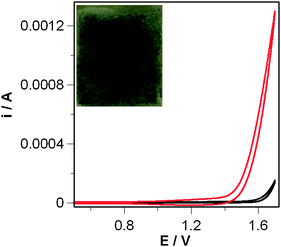 | ||
| Fig. 1 Cyclic voltammetric curves of FTO slides (R = 30 Ohm × cm) coated by Nafion® films only (blank, black curves) and Nafion/CoAPO5 films (red curves). Solution: 0.1 M K2SO4 in water. Scan rate 0.1 V s−1. 20 mg of catalyst was added on the slide dispersed in 0.3 mL of 5% w/w Nafion® isopropanol solution. Inset: picture of the FTO/Nafion/CoAPO5 photoanode. | ||
| E where water oxidation beginsa/V | i (+1.7 V)/μA | Δidirectb (60 s)/μA | Δidirect (400 s)/μA | |
|---|---|---|---|---|
| a E vs. sat. Ag/AgCl. Solution: 0.1 M K2SO4 in water, scan rate 0.1 V s−1. b Δidirect(t) = i(180 + t) − i(180) during a chronoamperometry at +1.6 V fixed potential. Please note that at t = 180 s light is turned on (direct illumination, intensity: 1 sun). Solution: 0.1 M K2SO4 in water. | ||||
| FTO/Nafion/CoAPO5 | +1.43 | 1299 | 125.2 | 354 |
| FTO/Nafion | +1.63 | 152 | 10.7 | 54.8 |
Subsequently, using the same electrode–electrolyte system, photoelectrochemical investigations were performed inside a darkroom. A plasma lamp that reproduces the solar spectra was used as a light source to illuminate the electrodes (intensity 1000 W m−2, see ESI† for details). A fixed potential of +1.6 V vs. Ag/AgCl was applied during the run to establish the water oxidation regime, and photocurrents were measured. The first 180 s were necessary to reach a steady state (plateau limit current under dark conditions), so as to make the detection of light-induced current steps more accurate. From 180 to 480 s the light source was switched ON in front of the cell (Fig. 2 and Table 1). By comparing the behaviour of the CoAPO5 photoanode and the blank (Fig. S8, ESI†) an increase in current of ca. 125 vs. 10 μA was evidenced after 60 seconds. Interestingly, this current difference between the Co containing sample and the blank goes on increasing with time, reaching a value of ca. 350 μA after 400 s. The formation of H2 and O2 during illumination was confirmed by GC measurements as described in ESI† (Fig. S6 and S7). The presence of an illuminated CoAPO5 catalyst increased the water oxidation current by 30–40% with respect to dark conditions (Fig. 2 and Fig. S4, ESI†), providing evidence of its activity in the light driven O2 production. The quantum yield of CoAPO5 upon electron–hole generation with respect to incident photons has been estimated to be 0.20–0.25% as discussed in ESI† (Fig. S4 and S5).
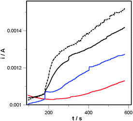 | ||
| Fig. 2 Current vs. time curve for the FTO/Nafion/CoAPO5 photoanode under different illumination conditions (Scheme S2 (ESI†) for setup): (i) dark room conditions (red curve); (ii) transversal illumination (blue curve); (iii) direct illumination (black curve); (iv) reverse illumination (broken curve). Solution: 0.1 M K2SO4 in water. Light program: 0–180 s dark; 180–580 s with light intensity of 1000 W m−2. E = +1.6 V vs. Ag/AgCl. | ||
The black curve in Fig. 2 shows, for CoAPO5, two well separated regions, a first “step-like” one ending at about 300 s and a second linear one.
Measurements with two different angles of light incidence (direct/transversal) were compared to cancel out the effect of a rise in temperature due to illumination, as well as any other possible spurious phenomenon (see Scheme S2, ESI†). Indeed, the blue curve (transversal illumination) parallels the later stages of the blank experiment (red curve), indicating that the linear increase is not really related to the presence of light. The difference between the current during direct and transversal illumination reaches a plateau after 250 s of illumination, thus indicating again that after that time the increase in current is related to spurious phenomena. Under the adopted conditions, the FTO/Nafion® films yield a small photocurrent, because FTO is a large bandgap semiconductor (ca. 3.8 eV) and the discharge lamp has 5% of UV light; such a photocurrent is about 10 μA (Fig. S8, ESI†).
When the FTO/Nafion/CoAPO5 photoanode is back-illuminated (Scheme S2, ESI†, broken curve in Fig. 2), a photocurrent is observed, which is larger than that recorded under frontal illumination by ca. 10 μA, i.e. the FTO contribution. This is because, in back-illumination the FTO is not shielded by the greyish CoAPO5 layer as in direct illumination.
Finally, it is worthy of note that no effect is observed when the UV component of the lamp light has been filtered off. This finally shows that the light used in the photochemical process is absorbed by CoAPO5 (Fig. S9, ESI†).
To rule out any important role of the FTO support in the photoactivity, data have been obtained by testing the catalyst on a Pt slide. 20 mg of CoAPO5 were dispersed in 0.3 mL of 5% w/w Nafion®-isopropanol solution and sonicated for 15 minutes. The suspension was then dropped onto a 4 cm2 Pt slide and left to dry for 12 h as done for the FTO substrate. The Pt/Nafion®/CoAPO5 slide was then used as a photoanode under the same experimental conditions as before and photocurrent was measured upon direct illumination (Fig. S10, ESI†). The chronoamperometry shows a neat increase in current with respect to blank Pt/Nafion® when light is turned on (∼6 mA), showing that the increase in current is associated only with CoAPO5.
Let us now consider the energy levels involved in electron transfer in the case of FTO/Nafion®/CoAPO5 (Scheme 1). The water oxidation reaction is based on the reduction of Co(III) centres to Co(II) species, according to the reaction shown in Scheme 1, that are generated again after the light-driven electron transfer to FTO. For CoAPO5, UV-VIS spectra indicate an energy difference of ca. 2.0 eV (Co(II) related transitions),18 whereas in the case of FTO the difference between valence and conduction bands is ca. 3.8 eV7. Because light exposure populates the CoAPO5 excited state (CoAPO5*), the minimum potential necessary for producing photocurrent equals the difference between CoAPO5* (electron donor level) and the conduction band of FTO (electron acceptor level). To measure this minimum potential for the onset of photocurrent, a photocurrent vs. E curve was obtained by subtracting the CV curve in the dark from the CV curve under illumination (Fig. 3). Each CV was repeated for 30 cycles until a stationary voltammetric curve was obtained. The value of potential where photocurrent is detected is ca. +0.8 V. Knowledge of such a value allows Scheme 1 to be drawn to scale, which shows that the transfer of an electron from Co(II) to the external circuit requires two contributions: the photoexcitation and a bias of at least +0.8 V vs. Ag/AgCl (Scheme 1).
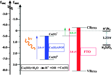 | ||
| Scheme 1 Basic diagram of the states involved in photoinduced electron transfer from the fundamental level of CoAPO5 to the conduction band of FTO. Note that under illumination a minimum bias of 0.8 V is necessary to obtain a photocurrent. | ||
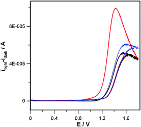 | ||
| Fig. 3 Photocurrent vs. E curve for the FTO/Nafion®/CoAPO5 photoanode during three successive voltammetric scans. Red curve: first cycle; blue curve: second cycle; black curve: third cycle. Experimental conditions are the same as already described in Fig. 1 and 2. The photocurrent has been calculated by subtracting the stationary CV in the dark from the one recorded under frontal illumination. | ||
The electrochemical results obtained using FTO and Pt substrates indicate that CoAPO5 acts as a combined water oxidation catalyst and visible light sensitizer. Indeed, it generates water oxidation currents in the presence of light starting from a bias of +0.8 V vs. Ag/AgCl. Considering the low cost, wide availability of reactants and easy preparation this porous material appears to be of interest for water photosplitting. Work is in progress to increase the maximum photocurrent by preparing nanostructured thin films to minimize the electron transfer distance and increasing the amount of accessible catalytic centres.
This research has been carried out in the context of the European Project “SOLHYDROMICS”.
Notes and references
- R. Asahi, T. Morikawa, T. Ohwaki, K. Aoki and Y. Taga, Science, 2001, 293(5528), 269 CrossRef CAS.
- W. Choi, A. Termin and M. R. Hoffmann, J. Phys. Chem., 1994, 98(51), 13669 CrossRef.
- X. Chen and S. S. Mao, Chem. Rev., 2007, 107(7), 2891 CrossRef CAS.
- K. Sivula, F. Le Formal and M. Gratzel, Chem. Mater., 2009, 21, 2862 CrossRef CAS.
- F. Le Formal, M. Grätzel and K. Sivula, Adv. Funct. Mater., 2010, 20, 1099 CrossRef CAS.
- K. Sivula, R. Zboril, F. Le Formal, R. Robert, A. Weidenkaff, J. Tucek, J. Frydrych and M. Grätzel, J. Am. Chem. Soc., 2010, 132, 7436 CrossRef CAS.
- M. Gratzel, Nature, 2001, 414, 338 CrossRef CAS.
- O. Khasalev and J. Turner, Science, 1997, 280, 425 CrossRef.
- C. S. Mullins and V. L. Pecoraro, Coord. Chem. Rev., 2008, 252, 416 CrossRef CAS.
- A. Hagfeldt, G. Boschloo, L. Sun, L. Kloo and H. Pettersson, Chem. Rev., 2010, 110(11), 6595 CrossRef CAS.
- M. G. Walter, E. L. Warren, J. R. McKone, S. W. Boettcher, Q. Mi, E. A. Santori and N. S. Lewis, Chem. Rev., 2010, 110(11), 6446 CrossRef CAS.
- (a) J. B. Gerken, J. G. McAlpin, J. Y. C. Chen, M. L. Rigsby, W. H. Casey, R. D. Britt and S. S. Stahl, J. Am. Chem. Soc., 2011, 133(36), 14431 CrossRef CAS; (b) M. Barroso, A. J. Cowan, S. R. Pendlebury, M. Grätzel, D. R. Klug and J. R. Durrant, J. Am. Chem. Soc., 2011, 133(38), 14868 CAS; (c) N. S. McCool, D. M. Robinson, J. E. Sheats and G. C. Dismukes, J. Am. Chem. Soc., 2011, 133(30), 11446 CrossRef CAS; (d) V. Artero, M. Chavarot-Kerlidou and M. Fontecave, Angew. Chem., Int. Ed., 2011, 50(32), 7238 CrossRef CAS; (e) Y. Surendranath, M. W. Kanan and D. G. Nocera, J. Am. Chem. Soc., 2010, 132, 16501 CrossRef CAS; (f) M. W. Kanan and D. G. Nocera, Science, 2008, 321(5892), 1072 CrossRef CAS.
- J. Meusinger, H. Vinek and J. A. Lercher, J. Mol. Catal., 1994, 87(2), 263 CrossRef CAS.
- J. Meusinger, H. Vinek, G. Dworeckow, M. Goepper and J. Lercher, Stud. Surf. Sci. Catal., 1991, 69(C), 373 CrossRef CAS.
- Y. He, M. Dong, J.-F. Li, J.-G. Wang and W. Fan, Acta Phys.–Chim. Sin., 2010, 26(5), 1305 CAS.
- S.-M. Yang, J.-Y. Lin, D.-H. Guo and S.-G. Liaw, Appl. Catal., A, 1999, 181(1), 113 CrossRef CAS.
- S. T. Wilson and E. M. Flanigen, US Pat., 4567,029, 2003 Search PubMed.
- (a) E. Schoonheydt, R. A. Vos, R. Pelgrims and H. Leeman, Stud. Surf. Sci. Catal., 1989, 49(A), 559 CrossRef; (b) B. Kraushaar-Czarnetzki, W. G. M. Hoogervorst, R. R. Andréa, C. A. Emeis and W. H. J. Stork, J. Chem. Soc., Faraday Trans., 1991, 87(6), 891 RSC; (c) A. Frache, L. Marchese, M. Cadoni, S. Coluccia, B. Palella, R. Pirone and P. Ciambelli, Stud. Surf. Sci. Catal., 2001, 140, 269 CrossRef CAS.
- A. Paul, M. Prabu, G. Madras and S. Natarajan, J. Chem. Sci., 2010, 122(5), 771 CrossRef.
Footnote |
| † Electronic supplementary information (ESI) available: Hydrothermal synthesis of CoAPO5; characterization of product; XRD spectrum, UV-VIS analysis of CoAPO5; electrochemical and photoelectrochemical setup; FTO/Nafion/CoAPO5 photoanode preparation; estimation of photons to “holes” conversion quantum yield; oxygen and hydrogen evolution measurements by gas chromatography (GC); scheme of the experimental setup for photoelectrochemical measurements; relative positions of light sources and photoanodes; view of the setup for combined electrochemical and gas chromatographic measurements; photocurrent vs. time of FTO/Nafion (blank); UV-VIS spectrum of calcinated CoAPO5; current vs. time plot for Pt/Nafion and Pt/Nafion/CoAPO5 photoanodes; effect of UV filtering on FTO/Nafion/CoAPO5 photocurrent. See DOI: 10.1039/c2cc17827c |
| This journal is © The Royal Society of Chemistry 2012 |