On the interplay between matter transport and structure formation at epoxy–hardener interfaces visualized by scanning Brillouin microscopy
Martine
Philipp
*a,
Ulrich
Müller
a,
Roland
Sanctuary
a,
John
Kieffer
b,
Wulff
Possart
c and
Jan Kristian
Krüger
a
aLaboratoire de Physique des Matériaux, University of Luxembourg, Luxembourg. E-mail: martine.philipp@uni.lu; Fax: +352 466 644 6331; Tel: +352 466 644 6784
bDepartment of Materials Science and Engineering, University of Michigan, Ann Arbor, USA
cWerkstoffwissenschaften, Universität des Saarlandes, Saarbrücken, Germany
First published on 5th October 2010
Abstract
Structural developments are investigated in network-forming reactive polymers by time- and space-resolved scanning Brillouin microscopy. Hypersonic properties are probed to reveal the subtle interplay between molecular transport, dissolution, polymerization and network defects in the vicinity of the interface between reactants, which are either pure epoxy resin or various epoxy resin–hardener mixtures, topped by a layer of pure hardener. The trans-interfacial polymerization produces heterogeneous epoxy structures of either gelatinous or glassy nature. Interestingly, the hardener can easily penetrate and swell these networks and epoxy network fragments can be transported over several millimetres by convective flow. The observed features may be used to form interpenetrating networks during self-healing procedures.
I. Introduction
Network-forming reactive polymers like epoxies are of tremendous technological importance.1–3 Due to the main application areas of epoxies as adhesives and protective layers, their mechanical properties are especially relevant.3–5 There is an ongoing discussion as to the extent to which these mechanical properties may be influenced by structural inhomogeneities ranging from a few tens of nanometres to the micrometre scale.6–11 The origin of such structural inhomogeneities is far from being understood.6–11 This lack of understanding might be due to the really complex interplay between physicochemical processes such as partial demixing of the epoxy educts, the polymerization of the resin, the hardener and larger oligomers, network defects, and the transport of molecules and network fragments during the polymeric network formation.To gain better insight into the subtleties of this structure formation we introduced scanning Brillouin microscopy12–14 as a method capable of probing molecular acoustic changes associated with the chemical reactions and molecular transport particularly at the phase boundary between liquid educts. Initial data-sets for the epoxy resin diglycidylether of bisphenol A (DGEBA) and the hardener diethylene triamine (DETA) have recently been published.13,14 These papers focused, amongst others, on the role of the demixing tendencies of the reactants for the network formation as seen by molecular acoustics investigations.15 The relevant results for the present article consist of: (i) the formation of convection channels of DETA inside DGEBA; (ii) the formation, transport, and destruction of local glassy epoxy aggregates in DGEBA; and (iii) the continuous material transport within the sample, more than 40 h after bringing the educts into contact.
In the present article we expand these molecular acoustics investigations15 towards systematically exploring the demixing tendencies between resin and hardener, and to encompass significantly longer observation times. Special attention is paid to the mutual influence of processes that govern the polymerization at the phase boundary between pure DETA hardener on one side and differently formulated epoxy resin–hardener mixtures on the other side, as well as in the bulk polymerization. We do not only concentrate on the zone close to the initial interface between the liquids, but analyze the acoustic behavior over roughly 15 mm around the interface for a duration of up to 150 h. Further, we examine the long time mechanical stability of the polymer network at glassy-to-gelatinous epoxy interfaces and the transport of network aggregates swollen by DETA against gravity. Finally we comment on the relevance of these acoustic investigations for the promising self-healing approach of polymer matrix composites based on mechanisms involving epoxy reactants.16–19
II. Experimental
A. Samples and sample preparation
Diglycidylether of bisphenol A, DGEBA DER 331 from DOW Europe was utilized as the resin. As this resin does not only contain DGEBA monomers but also dimers, trimers, etc., it can be easily supercooled below the melting temperature of the monomers, which lies approximately at 315 K.20 The mass density of DGEBA supercooled to 295 K is 1.16 g cm−3. The liquid hardener diethylene triamine (DETA) from Fluka possesses a density of 0.96 g cm−3 at 295 K.Well-mixed under-stoichiometric DGEBA/DETA mixtures with mass ratios of (100/5) and (100/10) (the stoichiometric ratio is 100/11) were prepared by stirring DGEBA and DETA using a glass rod for 4 min and then agitating the liquid mixtures using a speed-mixer from Hauschild for 30 s in order to remove any air bubbles. A well-mixed epoxy (100/10) undergoes a chemically driven glass transition after roughly 8 h of polymerization at 295 K, whereas the vitrification of the epoxy (100/5) cured at 295 K is supposed to happen after much longer times.21
Three different types of samples were prepared by carefully layering DETA on top of either DGEBA or one of the two concentrations of freshly prepared liquid DGEBA–DETA mixtures i.e., (100/5) or (100/10), in glass cuvettes with the dimension 1 × 1 × 4 cm3. The three sample types are designated as follows: the sample containing only DGEBA in the bottom compartment is denoted as R/H (‘resin/hardener’), whereas the others are called EP(100/5)/H and EP(100/10)/H, respectively. Taking into account the segregation tendency of the epoxy reactants and the smaller mass density of DETA compared to DGEBA and the polymerizing epoxies, respectively, we artificially create interfaces at which the reacting species are juxtaposed with fine spatial definition. For the R/H samples, DGEBA was filled to a level of 2 cm into the cuvette before a ∼1.5 cm thick layer of DETA was carefully stacked on top of it (see Fig. 1). For the EP/H samples, ca. 1 cm3 of the freshly prepared epoxy (100/5) or (100/10) was carefully filled into a cuvette. Compared to the R/H sample, a smaller volume of the bottom compartment was chosen for the EP/H samples in order to avoid any significant heating due to the reaction heat of the epoxy placed therein. Subsequently a ∼1.5 cm thick layer of DETA was carefully layered on top of the liquid well-mixed epoxies. Afterwards, the cuvettes were sealed with lids. All acoustic investigations were performed at room temperature, i.e. (295 ± 0.5) K.
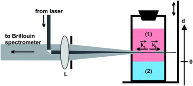 | ||
Fig. 1 Schematic view of the backscattering geometry and the cuvette on the scanning stage. (1) Upper DETA compartment, (2) bottom compartment containing DGEBA or the freshly prepared epoxies EP(100/5) or EP(100/10); ![[k with combining right harpoon above (vector)]](https://www.rsc.org/images/entities/char_006b_20d1.gif) i and s: wave vector of the incident and scattered laser light, L: lens, d: vertical axis fixed to the cuvette coordinate system with origin at the initial phase boundary between both compartments. Cuvette dimensions: 1 × 1 × 4 cm3. i and s: wave vector of the incident and scattered laser light, L: lens, d: vertical axis fixed to the cuvette coordinate system with origin at the initial phase boundary between both compartments. Cuvette dimensions: 1 × 1 × 4 cm3. | ||
B. Scanning Brillouin microscopy
Brillouin spectroscopy is an optical measurement technique that gives access to the hypersonic properties of optically transparent or translucent samples.22,23 It is especially well suited for our purpose as it provides spatially and temporally resolved information about the bulk properties of the sample, while being entirely non-destructive.This technique is based on the inelastic scattering of laser light by thermal phonons.24 Applying the law of energy conservation to this scattering process allows one to relate the hypersonic frequency f of the probed phonons to the angular frequencies ωs and ωi of the scattered and incident light, respectively, according to
| ħωs = ħωi ± 2π · ħf. | (1) |
Similarly the law of momentum conservation relates the wavevector ![[q with combining right harpoon above (vector)]](https://www.rsc.org/images/entities/i_char_0071_20d1.gif) of the phonon to the wavevectors s and i of the scattered and incident light according to
of the phonon to the wavevectors s and i of the scattered and incident light according to
ħ![[K with combining right harpoon above (vector)]](https://www.rsc.org/images/entities/i_char_004b_20d1.gif) s = ħi ± 2π · ħ s = ħi ± 2π · ħ | (2) |
In the backscattering geometry, shown in Fig. 1, the incident and scattered wave vectors i and s are antiparallel. The aperture of the collecting optics was chosen in such a way that under backscattering conditions the frequency uncertainty due to the spread of the acoustic wave vector is well below one percent. In this scattering geometry only the longitudinally polarized phonon doublet can be measured for an elastically isotropic and homogeneous sample. Scattering from transverse phonons is forbidden by symmetry.25 From the Brillouin spectrum the physically relevant hypersonic frequency f180L() and the temporal acoustic attenuation Γ180L() of the acoustic phonon can be obtained by deconvoluting the measured Brillouin doublet, taking into account the instrumental broadening along the optical path. The hypersonic frequency and attenuation correspond to the position and the half width at half maximum of the Brillouin lines, respectively. The statistical error of the hypersonic frequencies typically lies in the one-tenth of percent regime, whereas that of the attenuation is larger by roughly a factor of ten.
If the refractive index n of the material in the scattering volume is known, the longitudinal hypersonic velocity v180L can be determined according to:
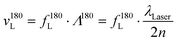 | (3) |
All measurements were performed using a modified six-pass tandem Brillouin spectrometer of the Sandercock type at (295 ± 0.5) K. Details about the experimental setup are given in Ref. 22 and 26. The laser power was kept below 5 mW at the sample cuvettes to avoid heating of the scattering volume. Indeed, the absence of thermal lensing was experimentally verified by reducing the laser power to such an extent that periodic intensity variations of the speckles pattern of the sample on a screen placed behind it were avoided. The needed spatial resolution for the present investigations was obtained by means of the scanning Brillouin microscopy (SBM) setup shown in Fig. 1.13,14 The SBM measurements were performed at spatial increments of 20 to 200 μm over a maximum distance of d = 15 mm. In order to obtain reliable phonon spectra, the accumulation time was at least 15 s for each spectrum. The vertical scanning of the cuvette was achieved by means of an electronically controlled scanning stage from Owis. As shown in Fig. 1, the origin of the d-axis was chosen at the position of the initial phase boundary between either DGEBA or the freshly prepared epoxy, and DETA. Recording spectra in the immediate vicinity of the phase boundary was possible because the meniscus at the interface is almost flat. The scattering volume corresponded to the laser beam's volume within the cuvette and had a length of 10 mm. Because the incident beam was focused near the center of the cuvette, the lateral dimension of the laser beam was not constant but varied between an estimated 10 to 50 μm. Thus, the Brillouin signal contained acoustic information that was spatially averaged over this scattering volume. Acoustic heterogeneities in the scattering volume could be noticed if their dimensions were larger than the acoustic wavelength and the difference of the frequencies involved could be resolved by the spectrometer. In that case, several phonon doublets could be recorded.
III. Results and discussion
Crucial for SBM investigations of trans-interfacial polymerization, matter transport processes, and accompanying structural developments near the initial interface, is the ability to carefully stack DETA on top of either DGEBA or freshly mixed, liquid epoxies. As far as visually perceptible we avoided mixing of the reactants at the interface, and created planar phase boundaries.The time needed for sample preparation and proper placement of the cuvette in the SBM setup is less than 15 min. The position of the initial interface is at d = 0 mm. The ‘time’ reported for each Brillouin scan is assigned to the moment when the scattering volume passes the position of the initial interface, measured relative to the moment when the reactants were layered in the cuvette. After sample preparation 24 spatial scans were performed over 43 h for the R/H-sample, 52 spatial scans over 146 h for the EP(100/5)/H-sample, and 49 spatial scans over 148 h for the EP(100/10)/H-sample. For the sake of clarity only part of the scans are shown here; these are representative for all measured data-sets.
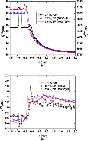
Fig. 2(a) shows longitudinal hypersonic frequency/velocity data f180L/v180L for early spatial scans performed after 0.5 h on the three samples. According to our previous investigations the hypersonic velocity of DETA is 1830 m s−1 and that of DGEBA is 2540 m s−1 at ambient temperature.13,14 Beyond d = 1 mm the hypersonic properties measured for all three samples correspond to those of pure DETA. When d < 0 mm the properties determined for the R/H sample are those of pure DGEBA, whereas for the EP/H samples the sound velocities determined after 0.5 h are the result of opposing influences due to dilution of DGEBA by DETA and due to polymerization of the liquid DGEBA–DETA mixture. While the former causes the sound velocity to decrease in comparison to that of pristine DGEBA, the latter causes it to increase.
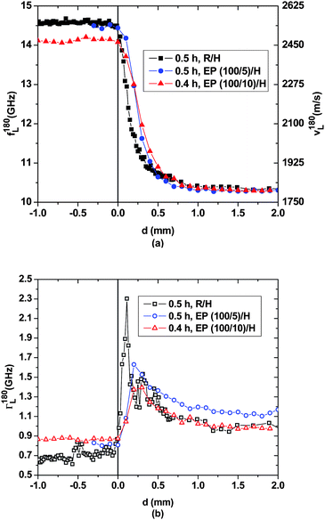 | ||
| Fig. 2 Spatial evolution close to the initial interface of (a) the hypersonic frequency f180L/velocity v180L and (b) the hypersonic attenuation Γ180L for the three layered samples after ∼0.5 h. | ||
The first half hour of molecular transport and chemical reactions only lead to small changes in the sound velocity profile near the interface. As can be seen in Fig. 2(a), sound velocities differ from the baseline of the respective pristine materials only within the first mm inside the DETA-rich region, marking the extent of the interphases that develop. According to the hypersonic properties, the acoustic interphases in the EP/H samples advance slightly faster into the DETA-rich compartment than in the R/H sample, during these early stages of the experiment. The rather small hypersonic attenuation of ∼0.65 GHz measured for DGEBA reflects the fact that structural dynamics stay close to the slow motion regime at GHz frequencies.23 The attenuation maxima in the interphase region are caused by pronounced coupling between molecular relaxation and acoustic wave propagation at hypersonic frequencies, and since this region can be considered as chemically and structurally transient between DGEBA and DETA, the hypersonic attenuation of ∼1 GHz in the latter likely corresponds to molecular dynamics that achieve significant relaxation on the ns time scale at room temperature.
According to Fig. 2 and 3, between 0.5 h and 2 h, epoxy bulk polymerization in the bottom compartment of the EP/H samples leads to a sound velocity increase of ca. 90 m s−1 and ca. 210 m s−1 for the (100/5) and (100/10) compositions, respectively. In the upper compartment, for d > 1.5 mm the hypersonic properties of pristine DETA prevail. Hence, over the first two hours of the experiment the acoustic interphases have only expanded by 1.5 mm into the DETA-rich compartment for all three samples. In addition, those of the EP/H samples have advanced by ∼0.4 mm into the epoxy-rich bottom compartments, as is evident from the gradual decrease of the hypersonic velocities starting at d ≈ −0.4 mm. DETA must have been transported into the liquid epoxy near the initial interface. Apparently at this stage of the experiment the dilution by the influx of DETA lowers the sound velocity more than the simultaneous epoxy polymerization manages to raise it.13,14,21 This interpretation of the observed phenomena is confirmed by the spatial variation of the hypersonic attenuation. The more gradual increase of the attenuation on the resin-rich side of the interface compared to earlier times reflects an increased structural gradient.
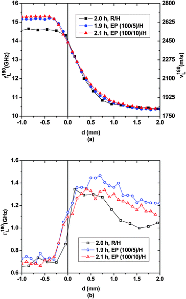 | ||
| Fig. 3 Spatial evolution of (a) the hypersonic frequency f180L/velocity v180L and (b) the hypersonic attenuation Γ180L for the three layered samples after ∼2.0 h. | ||
Consequently, the pronounced demixing tendency of DGEBA and DETA1 appears to be confirmed: when pure DGEBA and DETA are mutually exposed to each other at a planar interface only slight spontaneous interpenetration occurs and polymerization is slow and spatially confined. However, when some DETA molecules are mechanically mixed into the DGEBA resin prior to placing a layer of pure DETA on top, the demixing tendency between the two liquids is reduced and continued interpenetration of the reaction partners occurs more swiftly. The accompanying transport of DGEBA and oligomers into the DETA-rich compartment is acoustically less obvious to detect because of the extreme dilution of these molecules in DETA. According to Fig. 4, after roughly 8 h of the experiment the sound velocity curves for all three samples smoothly decay into the DETA-rich compartment, and the corresponding curves closely overlay. Judging by the spatial profiles at longer times presented below this might be coincidental. The most intriguing evolution of the interphases happens in the bottom compartment of the three samples. In the EP/H-samples for d < 0.5 mm the sound velocities approach typical values for glassy epoxy networks cured at room temperature (3100 to 3400 m s−1).23,26 This is consistent with the fact that polymerization is essentially completed after these times for the glass-forming (100/10) epoxy mixture, as well as the (100/5) mixture, which is almost glassy after these times. Interestingly, in the EP/H samples narrow sound velocity maxima have developed between d = −0.2 mm and d = −0.5 mm. These maxima obviously exceed the average sound velocities to be expected for the respective (under-stoichiometric) homogeneous mixtures after these polymerization times. Indeed, the highest sound velocities, exceeding 3300 m s−1, are observed for slightly over-stoichiometric well-mixed resin/hardener compositions.23 The fact that the hypersonic velocity maximum of the EP(100/5)/H sample appears closer to the initial phase boundary and needs an hour longer to develop than that of the EP(100/10)/H sample can be attributed to the prevailing demixing tendency between DETA and the EP mixture with the smaller amount of hardener. Hence, two opposing influences continue to affect the structural developments and the ensuing hypersonic properties in the epoxy-rich compartment: on the one hand DETA penetrates several 100 μm into that compartment and interacts with the already formed epoxy network in such a way that in the layer immediately adjacent to the original interface, the sound velocity is significantly lowered in comparison to the bulk reference state. On the other hand the increased DETA concentration causes a higher cross-link density,21 at least transiently, so that the sound velocities at the cusp considerably exceed those of the respective bulk epoxy. The hypersonic attenuations given in Fig. 4(b) suggest a more abrupt interphase between both compartments than indicated by the sound velocities.
 | ||
| Fig. 4 Spatial evolution of (a) the hypersonic frequency f180L/velocity v180L and (b) the hypersonic attenuation Γ180L for the three layered samples after ∼8 h. For each sample, the spatial profile is indicated for that time when the sound velocity peak in the bottom compartment is maximal. | ||
In our earlier papers13,14 we speculated that the sound velocity maximum observed around d ≈ −0.7 mm for the R/H-sample after 7 h is due to a glassy epoxy cluster embedded in a liquid DGEBA environment. The formation of the v180L-maxima in the EP/H samples supports this hypothesis. The main difference between both observations lies in the transport mechanisms for DETA: while for the EP/H samples diffusive transport across the initial phase boundary readily supplies sufficient DETA to form the v180L-maxima, in the R/H sample convective transport through micro-channels is needed to produce the sound velocity peak. Indeed, the scanning trace of the R/H sample shows the sound velocities of pure DGEBA in between the epoxy cluster and the initial interface, so that diffusive transport of DETA over the entire phase boundary cross section can be excluded as the underlying transport mechanism.
Fig. 5 shows the temporal evolution of interfacial and bulk polymerization measured at four positions in sample EP(100/10)/H. At d = −1 mm, i.e. within the epoxy bulk, the sound velocity increases as usually observed in a well-mixed polymerizing epoxy.23 As expected from earlier infrared spectroscopic and Brillouin spectroscopic investigations, the network formation in EP(100/10) levels after about 7 h.21,23 Within the DETA-rich compartment at d = 1 mm and d = 2 mm the sound velocity curves increase continuously over 18 h by ∼180 m s−1 and ∼90 m s−1, respectively. This behavior signifies that in the course of the first 18 h DGEBA and epoxy oligomers are transported from the epoxy/DETA interface into the DETA-rich compartment, where these molecules further polymerize. Obviously this process is continuing beyond 7 h, which is the saturation time for the polymerization in the epoxy bulk. Valuable information is furthermore gained from the temporal evolution of the sound velocity at d ≈ 0 mm. During the first hour after carefully layering DETA on top of the freshly mixed EP(100/10) the sound velocity slightly decreases by ∼90 m s−1 due to the penetration of the low viscosity EP(100/10) by DETA molecules. During the following 2.3 h polymerization dominates the sound velocity, which consequently increases again by roughly 90 m s−1. From then on the sound velocity continuously decreases. For up to 18 h, the dilution of epoxy oligomers by DETA, possibly causing swelling of network fragments that may have formed in the vicinity of the original interface, surpasses the effect of any additional polymerization.
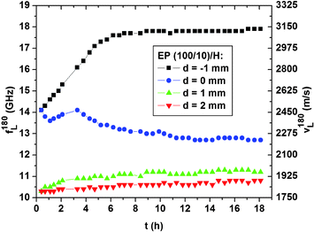 | ||
| Fig. 5 Temporal evolution during 18 h of the experiment of the hypersonic frequency f180L/velocity v180L for the sample EP(100/10)/H at 4 positions. | ||
For the R/H sample, measurements were carried out over 43 h. According to Ref. 13 and 14 at this time the sample has developed strong localized acoustic heterogeneities in the bottom compartment between d = −0.5 mm and −2 mm, indicative of glassy epoxy embedded in DGEBA. Fig. 6, focusing on the spatio-temporal progress of the acoustic profiles between 10 h and 144 h for the EP(100/5)/H sample, shows that no similar acoustic heterogeneities develop in the bottom epoxy-rich compartment of that sample. The aforementioned convection channels of DETA that facilitate the formation of the glassy heterogeneities in the bottom compartment of the R/H sample can apparently not develop in the EP/H samples. In the latter, polymerization quickly increases the static viscosity during the first hours in the bottom compartment, hindering convective transport. After ∼40 h the acoustic heterogeneities of the EP(100/5)/H sample increase in number and magnitude at the initial interface (see arrow in Fig. 6(a)), and seem to move deeper into the DETA-rich compartment with time. Since the polymerization occurs more rapidly in over-stoichiometric resin/hardener mixtures than in the bulk EP(100/5), it is unlikely that a significant number of unreacted oxirane groups (chemically reactive groups of DGEBA) would be present in the DETA-rich compartment after 10 h of the experiment. On the other hand, due to the dilution of resin by hardener the genesis of large epoxy networks therein seems implausible. Interestingly the spatially sharp transition in sound velocity between glassy and gelatinous epoxy shifts with time downwards from −0.2 mm to −1.3 mm. This indicates that DETA slowly penetrates into the glassy epoxy network, which swells to a gelatinous state. Shear stresses acting on the polymeric chains of the swollen epoxy close to the glassy-to-gelatinous interface probably lead to rupture of the epoxy structure and the dislodging of network fragments that float relatively freely into the DETA-rich compartment. This is, for example, indicated by the shift in the sound velocity bump identified by the arrows in Fig. 6(b). A possible interpretation of the corresponding two spatial profiles would be that within a time frame of roughly 50 h a swollen epoxy aggregate is transported upwards by 3.5 mm, starting from the position d = 2 mm.
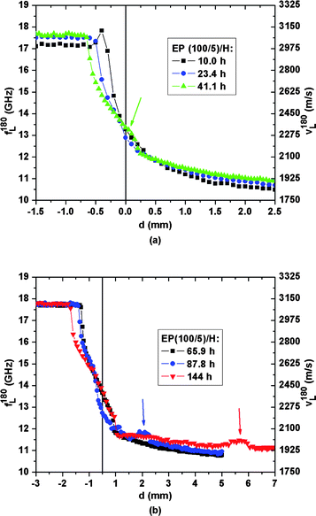 | ||
| Fig. 6 Spatial evolution of the hypersonic frequency f180L/velocity v180L for the EP(100/5)/H sample between (a) 10.0 h and 41.1 h, (b) 65.9 h and 144 h. | ||
Even stronger support for the hypothesis of convective flow of swollen epoxy pieces is provided in Fig. 7(a), which focuses on the spatio-temporal development of sound velocities in the DETA-rich region of the EP(100/10)/H sample between 128 and 144 h. The persistent shape of all sound velocity profiles in this figure, while steadily shifting to higher d-values, strongly suggests that one or several well-identifiable gelatinous epoxy pieces are indeed transported upwards by roughly 1 mm during the course of 16 h. An explanation of this convective upward flow of epoxy pieces against gravity is not straightforward. A possible explanation is as follows: epoxy pieces located close to the glassy epoxy interface swell due to DETA penetration and thus increase in volume. This swelling-induced volume expansion lifts all material placed on top of the swelling epoxy pieces. The upward transport process is maintained by the ongoing genesis of new epoxy fragments at the epoxy interface. Thus chemical affinities between the epoxy network fragments and their solvent DETA are amongst the driving forces responsible for the upward transport of gelatinous epoxy. Those epoxy pieces leading to the sound velocity bumps in Fig. 6(b) seem to be almost saturated by DETA as after more than 120 h their sound velocities almost do not decrease any more.
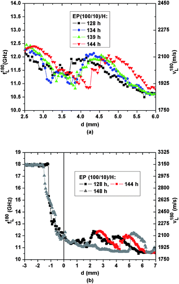 | ||
| Fig. 7 Spatial evolution of the hypersonic frequency f180L/velocity v180L for the EP(100/10)/H sample between (a) 128 h and 144 h, (b) spatial heterogeneity shown after 144 h. An additional spatial scan, shown as triangles, was measured after horizontally shifting the scattering volume by ∼2 mm within the cuvette. | ||
To further substantiate the spatial extent of acoustic heterogeneity across the samples, the cuvettes were shifted laterally by about 2 mm for both EP/H samples and additional scans were performed at approximately 150 h. The corresponding data are shown for the EP(100/10)/H sample as triangles in Fig. 7(b). Deep in the epoxy compartment, i.e. for d < −2 mm, the sound velocities still correspond to those of glassy epoxy, and lateral variation of the acoustic properties is not observed. However, the sound velocity profiles exhibit lateral fluctuations as large as 200 m s−1 in the upper compartment, which can be attributed to the fact that the scanning traces intersect with different gelatinous epoxy aggregates or, in case these aggregates do percolate, they have irregular shapes and their mechanical constitution fluctuates between those of a gelatinous network and a highly viscous liquid. In fact, we were able to isolate such aggregates from the cuvette using tweezers. Drying of these aggregates led to glassy epoxy, which confirms their high degree of reticulation.
Our observations may have important implications for the practical implementation of the reagent mixing in epoxy systems. The quality of dispersion of the reacting partners in one another and the resulting degree of homogeneity may need to be quantitatively assessed for specific technological applications. For example, in epoxy-based self-healing composites, where DGEBA and/or DETA are released from embedded capsules at the tips of fatigue cracks, the effectiveness of this strategy depends on the size and placement of these capsules. Our investigations reveal that in principle DETA can penetrate into the glassy epoxy at the crack faces and lead to the formation of a new epoxy network partially interpenetrating the broken epoxy network.
IV. Conclusions
Scanning Brillouin microscopy performed over a span of 150 h on samples in which DETA was layered on top of either DGEBA or freshly prepared liquid resin/hardener mixtures reveals the development of complex acoustic and thus structural heterogeneities that evolve with time and location. When pure DGEBA is offered in the bottom compartment, the hardener DETA mainly penetrates this region from the top through small convective channels. Reaction takes place at the end of these channels, which leads to the formation of isolated glassy polymer fragments away from the interface. This mechanism does not manifest in the samples containing freshly prepared liquid epoxy in the bottom compartment, as the network grows quickly and the viscosity soon becomes too high for the channels to develop. The present acoustic measurements obtained on DETA layered on top of different epoxy mixtures strongly supports the idea that DETA swells the formed epoxy network and that the swollen network ruptures to release fragments that are subject to convective transport against gravity into the DETA-rich zone. Astonishingly, this rupture still takes place after more than 100 h and the convection processes proceed over distances of several millimetres. The epoxy pieces located close to the glassy epoxy interface swell due to DETA penetration and thus increase in volume. This swelling-induced volume expansion lifts all material placed on top of the swelling epoxy pieces. Thus chemical affinities between the epoxy network fragments and their solvent DETA are amongst the driving forces responsible for the upward transport of gelatinous epoxy.The above observations indicate that for epoxies using DGEBA and DETA as healing agents, the self-healing process may occur not only by pure interfacial adhesion but also by the formation of a network interphase that penetrates the damaged epoxy close to the crack boundaries.
Notes and references
- B. Ellis, Chemistry and technology of epoxy resins, Chapman & Hall, London, 1993 Search PubMed.
- K. Friedrich, S. Fakirov and Z. Zhang, Polymer composites. From nano- to macro-scale, Springer, New York, 2005 Search PubMed.
- J. P. Pascault, Thermosetting polymers, Marcel Dekker, New York, 2002 Search PubMed.
- Q. L. Ji, M. Q. Zhang, M. Z. Rong, B. Wetzel and K. Friedrich, J. Mater. Sci., 2004, 39, 6487–6493 CrossRef CAS.
- B. Wetzel, P. Rosso, F. Haupert and K. Friedrich, Eng. Fract. Mech., 2006, 73, 2375–2398 CrossRef.
- K. Dušek, Angew. Makromol. Chem., 1996, 240, 1–15 CrossRef.
- J. Mijovic and L. Tsay, Polymer, 1981, 22, 902–906 CrossRef CAS.
- U. Müller, R. Bactavatchalou, J. Baller, M. Philipp, R. Sanctuary, B. Zielinski, P. Alnot, W. Possart and J. K. Krüger, New J. Phys., 2008, 10.
- T. Takahama and P. G. Geil, Makromol. Chem. Rapid Commun., 1982, 3, 389–394 CrossRef CAS.
- C. Wehlack, W. Possart, J. K. Krüger and U. Müller, Soft Mater., 2007, 5, 87–134 Search PubMed.
- B. Wetzel, PhD Thesis, Technische Universität Kaiserslautern, 2005.
- M. Philipp, F. Collette, M. Veith, P. Seck, R. Sanctuary, U. Müller, K. J. and J. K. Krüger, J. Phys. Chem. B, 2009, 113, 12655–12662 CrossRef CAS.
- R. Sanctuary, M. Philipp, U. Müller, W. Possart, R. J. Jiménez Riobóo and J. K. Krüger, Chem. Phys. Lett., 2009, 476, 11–14 CrossRef CAS.
- R. Sanctuary, M. Philipp, J. Kieffer, U. Müller, W. Possart and J. K. Krüger, J. Phys. Chem. B, 2010, 114, 8396–8404 CrossRef CAS.
- W. Schaaffs, Molecular acoustics, Springer, Berlin, 1967 Search PubMed.
- B. J. Blaiszik, M. M. Caruso, D. A. McIlroy, J. S. Moore, S. R. White and N. R. Sottos, Polymer, 2009, 50, 990–997 CrossRef CAS.
- D. A. McIlroy, B. J. Blaiszik, M. M. Caruso, S. R. White, J. S. Moore and N. R. Sottos, Macromolecules, 2010, 43, 1855–1859 CrossRef CAS.
- K. S. Toohey, C. J. Hansen, J. A. Lewis, S. R. White and N. R. Sottos, Adv. Funct. Mater., 2009, 19, 1399–1405 CrossRef CAS.
- D. Y. Wu, S. Meure and D. Solomon, Prog. Polym. Sci., 2008, 33, 479–522 CrossRef CAS.
- J. L. Flippen-Anderson and R. Gilardi, Acta Crystallogr., Sect. B: Struct. Crystallogr. Cryst. Chem., 1981, 37, 1433–1435 CrossRef.
- U. Müller, New J. Phys., 2010, 12, 083036 CrossRef.
- J. K. Krüger, in Optical Techniques to Characterize Polymer Systems, ed. H. Bässler, Elsevier, Amsterdam, 1989 Search PubMed.
- J. K. Krüger, P. Alnot, J. Baller, R. Bactavatchalou, S. Dorosz, M. Henkel, M. Kolle, S. P. Krüger, U. Müller, M. Philipp, W. Possart, R. Sanctuary and C. Vergnat, in Ageing and the Glass Transition, ed. M. Henkel, M. Pleimling and R. Sanctuary, Springer, Berlin, 2007 Search PubMed.
- J. B. Berne and R. Pecora, Dynamic light scattering with applications to chemistry, biology, and physics, Wiley, New York, 1976 Search PubMed.
- R. Vacher and L. Boyer, Phys. Rev. B: Solid State, 1972, 6, 639–673 CrossRef CAS.
- J. K. Krüger, U. Müller, R. Bactavatchalou, D. Liebschner, M. Sander, W. Possart, C. Wehlack, J. Baller and D. Rouxel, in Adhesion - Current research and applications, ed. W. Possart, Wiley-VCH, Weinheim, 2005, pp. 125–142 Search PubMed.
| This journal is © The Royal Society of Chemistry 2011 |