Retracted Article: Self-assembled organic nanotubes embedding hydrophobic molecules within solid bilayer membranes
Naohiro
Kameta
*,
Masumi
Asakawa
,
Mitsutoshi
Masuda
and
Toshimi
Shimizu
*
Nanotube Research Center (NTRC), National Institute of Advanced Industrial Science and Technology (AIST), Tsukuba Central 5, 1-1-1 Higashi, Tsukuba, Ibaraki 305-8565, Japan. E-mail: n-kameta@aist.go.jp; Fax: +81-29-861-4545
First published on 1st October 2010
Abstract
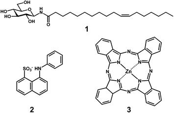
We have carried out co-assembly of N-(11-cis-octadecenoyl)-β-D-glucopyranosylamine 1 with hydrophobic molecules, 8-anilinonaphthalene-1-sulfonate (1,8-ANS) 2 or Zn-phthalocyanine 3 in a mixed solvent of organic solvents and water to form nanotubes embedding the hydrophobic molecules. Transmission electron microscopic (TEM), fluorescence microscopic observations, and X-ray diffraction (XRD) analysis revealed the formation of nanotubes where the interdigitated bilayer membranes of 1 function as an embedded matrix for the hydrophobic molecules. We have compared the release behavior of 2 embedded in the bilayer membranes with that of 2 encapsulated inside the nanotube hollow cylinder of 60-nm inner diameter. Although the encapsulated molecules 2 proved to be slowly released from both open ends of the hollow cylinder at room temperature, the embedded ones kept staying in the bilayer membranes. Similarly, the embedded molecules 3 kept staying in the interdigitated bilayer membranes at temperatures below a thermal phase transition temperature (Tg-l = 59 °C) of the nanotubes. However, when the solid-state bilayer membranes of the nanotubes converted into a fluid bilayer membrane at temperatures above the Tg-l, the molecules 3 was instantly released. Such self-assembled nanotubes embedding hydrophobic molecules are applicable to medical diagnosis systems containing deliveries of drugs, photosensitizers, fluorescence- and spin-probes.
Introduction
Self-assembly of rationally designed amphiphiles in water can produce tubular nanoarchitectures with well-defined size-dimensions as well as functional inner and outer surfaces.1 The self-assembled nanotubes provide a hydrophilic hollow cylinder with 10–100 nm inner diameters, which is applicable to not only templates2–5 to align nanomaterials one-dimensionally or to fabricate metal nanowires but also containers6–8 or channels9,10 to encapsulate, transport, and release biomacromolecules. Systematic studies on the functions of the nanotube hollow cylinder have contributed to elucidation of unique profile of the nanospace.11–16 For example, the confinement effect, which depends on the size balance between the nanotube inner diameter and guest biomolecules, allows the nanotube to stably store those biomolecules while keeping the active state under harsh conditions of temperatures and denaturant concentrations.17–19 The outer surfaces covered with hydrophilic headgroups of the amphiphiles also play important roles in recognition and sensing of a target guest,20–23 adsorption of DNA for the gene delivery,24 sol–gel reactions to construct organic–inorganic hybrid nanotubes,25 and patterning of nanoparticles.26 Liposomes and vesicles have been widely applied to drug-delivery and medical diagnosis systems, utilizing both closed hollow space and fluid bilayer membranes.27,28 They have been known to encapsulate biomolecules or hydrophilic drugs and can embed hydrophobic drugs or photosensitizers or fluorescence-, spin-probes, respectively. However, systematic and quantitative studies on the inside of the nanotube membranes consisting of hydrophobic long-alkyl chains of the amphiphiles have been limited.29–31Herein, we demonstrate that hydrophobic molecules, 8-anilinonaphthalene-1-sulfonate (1,8-ANS) 2 or Zn-phthalocyanine 3 can be embedded in the bilayer membranes of self-assembled nanotubesvia the co-assembly technique in a mixed solvent of organic solvents and water. We describe the embedding and release behavior of the hydrophobic molecules by the self-assembled organic nanotube when varied.
Experimental
Preparation of nanotubes
N-(11-cis-Octadecenoyl)-β-D-glucopyranosylamine 132 (1 μmol) was dissolved in a methanol–ethyl acetate (1![[thin space (1/6-em)]](https://www.rsc.org/images/entities/char_2009.gif) :1, v/v) solution (0.4 ml). The solution was poured into water (20 ml), and then the mixture allowed to stand overnight to complete the formation of nanotubes.
:1, v/v) solution (0.4 ml). The solution was poured into water (20 ml), and then the mixture allowed to stand overnight to complete the formation of nanotubes.
Preparation of nanotubes embedding hydrophobic molecules within bilayer membranes
The methanol–ethyl acetate (1:1, v/v) solution (0.4 ml) of 1 (1 μmol) and the ammonium salt of 2 (0.1–10 μmol) or 3 (0.1–1 μmol) was mixed with water (20 ml), and then the mixture was left overnight. The mixture containing 2 was filtered by using a polycarbonate membrane with 0.2 μm pore size. The formed nanotubes did not pass the membrane because of the high-axial ratio structures. The residual nanotubes were washed several times by the methanol–ethyl acetate (1:1, v/v) solvent mixture to remove the free 2 existing outside and the encapsulated 2 in the hollow cylinder of the nanotubes. The mixture containing 3 was subjected to centrifugation (10,000 rpm). Dispersed nanotubes in the supernatant solution were separated from the free 3 precipitated as a solid. Complete destruction of the nanotubes by heating in dimethyl sulfoxide (DMSO) enabled us to calculate the amount of the embedded 2 or 3. In actual, the concentrations of 2 and 3 were determined by a fluorescence spectroscopy and gravimetric analysis, respectively. Fluorescence spectra for the released 2 in DMSO were measured by using F-4500 spectrophotometer (HITACHI) equipped with DC1 temperature control (HAAKE). Gravimetric analysis using a microbalance (METTLER TOLEDO) for the released 3 was carried out after complete removal of DMSO by the membrane filtration and vacuum drying.
Preparation of nanotubes encapsulating 1,8-ANS in the hollow cylinder
The lyophilized nanotubes ([1] = 1 μmol) was added in an aqueous solution of 2 (1–10 μmol). After aging overnight, we collected the nanotubes encapsulating 2 in the hollow cylinder from the aqueous solution in a similar filtration procedure.Transmission electron microscopic (TEM) observation
The aqueous dispersion of the intrinsic nanotubes or the nanotubes embedding 2 or 3 was dropped onto a carbon grid and dried by standing at room temperature. The nanotubes, negatively stained with a phosphotungstate solution (2 wt%, pH adjusted 7 by NaOH), were observed by TEM (Hitachi, H-7000) at 75 kV.Fluorescence microscopic observation
Fluorescence microscopic observation for the embedded 2 in the nanotube membranes was performed by using inverted microscope (OLYMPUS IX71) equipped with CCD camera (HAMAMATSU ORCA-ER). Excitation optical source was prepared by a high pressure mercury lump (100 W, OLYMPUS BH2-REL-T3) and a 330–385 nm band pass filter.X-Ray diffraction (XRD) measurements
XRD patterns of the lyophilized nanotubes and the lyophilized nanotubes embedding 2 or 3 were measured with a Rigaku diffractometer (Type 4037) using graded d-space elliptical side-by-side multilayer optics, monochromated Cu-Kα radiation (40 kV, 30 mA), and an imaging plate (R-Axis IV). The exposure time was 5 min with a 150 mm camera length.Calculation of release ratio (%)
The release ratio (%) of 2 from the nanotubes to a bulk water was calculated after a certain time by using a maximum fluorescence intensity at 525 nm for the released 2 in water and the corresponding calibration curve. The fluorescence intensity was measured for each filtrate treated with the polycarbonate membrane. The release ratio (%) of 3 was also calculated in a similar way by using a weight of the released 3 in water. The weight was measured for each precipitate treated by centrifugation.Electro-spray ionization mass spectrometry (ESI-MS) measurement
The precipitate recovered from above release experiment of 3 was subjected to ESI-MS measurement to investigate the purity and chemical composition of 3. DMSO containing pyridine, which can coordinate Zinc and prevent aggregations of 3, was used as a sample solvent. ESI-MS spectrometer (Waters ZQ2000) was operated in the positive-ion mode.Optical microscopic observation
The polarized-optical microscopy image of fully hydrated nanotubes embedding 3 was recorded using a polarized light microscope (Olympus BX51) equipped with 3-CCD video camera recorder (Olympus CS530MD). Temperatures were controlled using a Mettler FP82 hot stage linked to a Mettler FP90 with an accuracy of 0.4 °C.Differential scanning calorimetry (DSC) measurement
The DSC profile of the hydrated nanotubes embedding 3 (1 mg mL−1) placed into an aluminium pan was recorded at 25–80 °C using a differential scanning calorimeter (DSC 6100, SEIKO) equipped with a nitrogen gas cooling unit. The peak temperature was taken as the phase transition temperature.Results and discussions
Formation of nanotubes in a mixed solvent of organic solvents and water
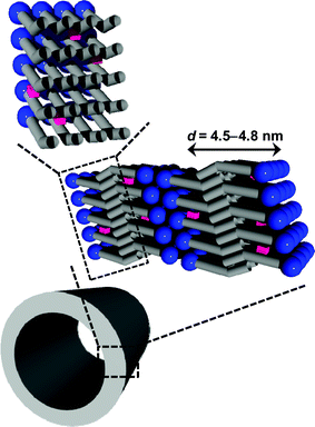
Fig. 1a shows a TEM image of the self-assemblies formed after mixing the methanol–ethyl acetate (1:1, v/v) solution of 1 with water at room temperature. The penetration of the negative staining reagent, phosphotungstate, into the hollow cylinder can strongly support that the self-assembled morphologies take tubular structures (abbreviated as M-nanotube hereafter). The 60 nm inner diameter of the M-nanotube is compatible with that of the nanotube (abbreviated as W-nanotube hereafter)32 self-assembled from 1 in water under reflux conditions.
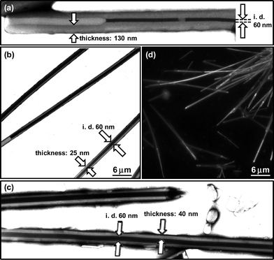 | ||
| Fig. 1 TEM images of the (a) M-nanotube, (b) nanotubes embedding 2 and (c) nanotubes embedding 3, which were negatively stained with phosphotungstate. The hollow cylinder nanospace of organic nanotubes is visible with relatively darker contrast than surrounding. (d) Fluorescence microscopic image of the nanotubes embedding 2. | ||
XRD measurement of the M-nanotube gave a sharp diffraction peak in the small-angle region (Fig. 2a), indicating that the nanotube consists of bilayer membranes with a stacking periodicity (d = 4.45). Since the d value was similar to that of the W-nanotube, the molecules 1 should pack in an interdigitated fashion within the bilayer membranes as well as the W-nanotube.32 Namely, the present nanotube was similar in the size dimension and molecular packing to the W-nanotube irrespective of the coexistence of organic solvents in the present self-assembly system.
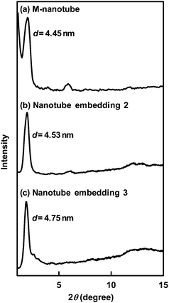 | ||
| Fig. 2 XRD spectra of the (a) M-nanotube, (b) nanotubes embedding 2 and (c) nanotubes embedding 3. | ||
We found that 1 also self-assembled in the mixed solvents of organic solvents and water to form the nanotubes. This methodology should be suitable for embedding of hydrophobic molecules in nanotubes. The co-assembly of the hydrophobic molecules with 1 in the mixed solvent will prevent the hydrophobic molecules from thermal decomposition, which occurs in the self-assembly procedure accompanying heating.
Embedding of 1,8-ANS in solid bilayer membranes of nanotubes
First, we chose an environment-responsive probe, 1,8-ANS (2), as a target molecule, since we can easily confirm detailed location of the fixed 2 in the nanotubes by fluorescence spectroscopy.33Fig. 1b shows a TEM image of the self-assemblies formed by mixing the methanol–ethyl acetate (1:1, v/v) solution of 1 in the presence of 2 (10 eq.) with water at room temperature. The obtained self-assemblies are assignable to tubular structures, since the hollow cylinder is clearly visible by the negative staining reagent. The inner diameter (60 nm) of the nanotubes remained unchanged after the fixation of 2, when compared with that of the M-nanotube formed in the absence of 2 in the similar mixed solvent (Fig. 1a and 1b). However, the membrane thickness (25 nm) was found to be remarkably thinner than that (130 nm) of the M-nanotube. Fluorescence microscopic observation revealed blight fluorescence of 2 along the axis of each nanotube (Fig. 1d), indicating that 2 is widely dispersed in the bilayer membranes or hollow cylinder. Adsorption of 2 onto the outer surfaces of the nanotubes may give similar fluorescence. However, we can ignore the fluorescence derived from the adsorption, since we completely removed 2 existing outside of the nanotubes by the membrane filtration. Fig. 3 indicates the relationship between the amount of the fixed 2 in the nanotubes and that of the initial 2. The maximum amount of the fixed 2 proved to be about 0.12 μmol against the 1 μmol of 1.
![Relationship between the amounts of the initially used 2 or 3 and the embedded molecules in the nanotubes ([1] = 1 μmol).](/image/article/2011/SM/c0sm00375a/c0sm00375a-f3.gif) | ||
| Fig. 3 Relationship between the amounts of the initially used 2 or 3 and the embedded molecules in the nanotubes ([1] = 1 μmol). | ||
The fluorescence spectra of the fixed 2 in the nanotubes were compared with those of the encapsulated 2 in the nanotube hollow cylinder as well as the free 2 in the bulk (Fig. 4). We already found that the encapsulated 2 in a nanotube hollow cylinder of 10 nm inner diameter, whose surfaces are similarly covered with the glucose headgroups, gave a blue-shifted fluorescence peak.34 This phenomenon is attributable to relatively higher viscosity and lower polarity of confined water in the nanotube hollow cylinder. The fluorescence peak of the encapsulated 2 in the hollow cylinder of the present nanotube with 60 nm inner diameter was also observable in the relatively shorter wavelength region (480–510 nm), when compared with that (525 nm)35 of 2 in the bulk. However, the degree of the blue shift was slightly smaller than that of the previous one because of the larger inner diameter. On the other hand, the fluorescence spectrum of the fixed 2 in the nanotubes prepared by the present method was easily distinguishable from that of the encapsulated 2 in the nanotube hollow cylinder. The larger blue shift (the peak at 410 nm), the strong intensity, and the narrow shape of the corresponding peak, which are compatible with those of 2 in n-heptane,34 strongly suggest that 2 locates in the hydrophobic part of the nanotubes. The embedded 2 in the hydrophobic domain of cylindricalmicelles like nanofibers self-assembled from glycolipids showed similar fluorescence spectral features.36 Namely, the co-assembly of 1 with 2 in the mixed solvent allowed 2 to be embedded within the bilayer membranes consisting of the long-alkyl chains of 1 (Fig. 5). The d value (= 4.53 nm) of the nanotube embedding 2 was similar to that of the M-nanotube (Fig. 2), indicating that 2 never interferes the interdigitated molecular packing of 1 within the bilayer membranes. However, the embedding will prevent the membrane growth by the stacking of the bilayers. As a result, the nanotubes embedding 2 have relatively thinner membrane thickness compared with that of the M-nanotube (Fig. 1b).
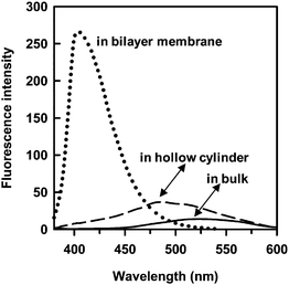 | ||
| Fig. 4 Fluorescence spectra of the embedded 2 in the nanotube bilayer membranes (dotted line, 1.3 × 10⁻⁵ M), the encapsulated 2 in the nanotube hollow cylinder (dashed line, 1.5 × 10⁻⁵ M), and the free 2 in bulk water (solid line, 1.5 × 10⁻⁵ M). | ||
 | ||
| Fig. 5 Schematic illustration for the embedding of hydrophobic molecules within the bilayer membranes of the self-assembled nanotubes. | ||
The release behavior of the embedded 2 in the bilayer membranes was compared with that of the encapsulated one in the hollow cylinder (Fig. 6). The encapsulated 2 in the hollow cylinder proved to be slowly released from both open ends with lapse of time at 25 °C. The driving force was attributable to the difference in the concentration of 2 between the nanotube hollow cylinder and the bulk solution. On the other hand, the embedded 2 was hardly released under same conditions. Stable embedding of 2 at 25 °C may be due to a solid state of the bilayer membranes, which will be discussed in the following section.
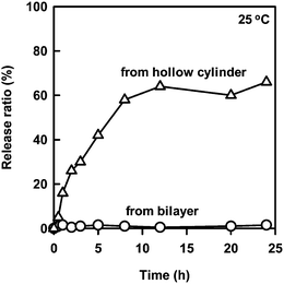 | ||
| Fig. 6 Time dependence for the release rate of the embedded 2 (1.3 × 10⁻⁵ M) and the encapsulated 2 (1.5 × 10⁻⁵ M) from the nanotubes to the bulk water at 25 °C. | ||
Embedding of Zn-phthalocyanine in solid bilayer membranes of nanotubes
We also chose Zn-phthalocyanine (3) as a target hydrophobic molecule, since improved dispersibility of 3 in aqueous solutions will be benefit to utilization as a photosensitizing agent for a photodynamic therapy.28b, 37 We performed the embedding of 3 in the nanotube bilayer membranes by mixing the methanol–ethyl acetate (1:1, v/v) solution of 1 in the presence of 3 (0.1–1 eq.) with water at room temperature. TEM observation (Fig. 1c) and XRD measurement (Fig. 2c) confirmed that the size dimensions of 60 nm inner diameter, 40 nm thickness and d spacing (4.75 nm) for the nanotubes embedding 3 are similar to those of the nanotubes embedding 2. We estimated the maximum amount of the embedded 3 under given conditions to be about 0.2 μmol against the 1 μmol of 1 (Fig. 3). Although 3 has a relatively larger-molecular weight than 2, the amount of the embedded 3 was much larger than that of the embedded 2. This phenomenon supports that the embedding efficiency strongly depends on the hydrophobic interaction between the guest molecules and the long-alkyl chains of 1 within bilayer membranes. Solubility of 3 in water is very poor due to the high hydrophobicity, while 2 having hydrophilic sulfonate group dissolves in not only organic solvents but also water. Both sharp peaks of excitation and emission spectra of the embedded 3 supported that the 3 does not aggregate and exist as a monomer specie in the solid bilayer membranes (Fig. 7).38 The dispersion of 3 as a monomer specie is valuable for the photodynamic therapy, since the aggregate diminishes the photosensitizing ability.39
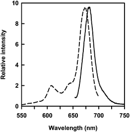 | ||
| Fig. 7 Excitation (dotted line) and emission (solid line) spectra of the embedded 3 in the nanotube bilayer membranes. | ||
Release behavior of the embedded 3 was examined under various temperature conditions. The release rate proved to hardly change after 10 min in the elevated temperature range (20–40 °C) (Fig. 8a). The nanotubes turn out to hold the embedded 3 as well as the embedded 2 because of the solid bilayer membranes. Fig. 8b (left) indicates a photograph for the aqueous dispersion of the nanotubes embedding 3. The aqueous dispersion in blue color means that 3 is well dispersed as a chromophore. However, further increase in temperatures (60–80 °C) allowed the nanotubes to drastically enhance the release rate after 10 min (Fig. 8a). The released 3 was not dispersed in water because of the high hydrophobicity of 3, and resulted into precipitation (Fig. 8b, right). ESI-MS measurement for the precipitate, which was completely dissolved in DMSO containing pyridine, clearly indicated a mass number of 737.1, which corresponds to mass value of 3 + 2 pyridine + H+. We did not observe mass numbers related to 1, although 1 can be easily dissolved as a molecular monomer in DMSO. This result suggests that the precipitate involves no 1. We already reported that a solid-state W-nanotube converts into fluid-state self-assemblies like vesicles at temperatures above the thermal phase transition temperature (Tg-l = 71 °C).32DSC measurement for the concentrated and the hydrated nanotubes embedding 3 indicates an endothermic peak corresponding to the thermal phase transition (Fig. 8a). Polarized microscopic observation also showed a streak texture at 60 °C (Fig. 8c), suggesting the formation of a liquid crystalline phase. The slightly lower Tg-l (= 59 °C) of the present nanotube will be ascribable to partial disorder of the molecular packing induced by the embedding of 3. Fluid bilayer membranes should promote the release of the embedded 3, since the releasing behavior of embedded molecules in liposomes strongly depends on fluidity of the bilayer membranes.40
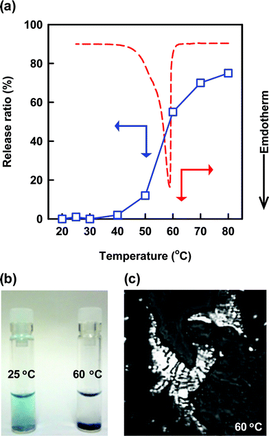 | ||
| Fig. 8 (a) Temperature dependence for the release rate of the embedded 3 from the nanotubes (blue square plots). Incubation time after elevating the temperature to a certain one is 10 min. DSC profile for the fully hydrated nanotubes embedding 3 on the first heating cycle (red line). (b) The real appearance for (left) the dispersed solution of the embedded 3 in the nanotube bilayer membranes at 25 °C and (right) the precipitation of the released 3 from the fluid bilayer membranes at 60 °C. (c) Polarized optical microscopic image of the fully hydrated nanotubes embedding 3 at 60 °C. | ||
Conclusion
We have demonstrated that the co-assembly of the amphiphile and the hydrophobic molecules in the mixed solvent of organic solvents and water allowed for the embedding of hydrophobic molecules in the solid bilayer membranes of the self-assembled nanotubes. We have found that the embedded hydrophobic molecules are stably embedded in the membranes at temperatures below the thermal phase transition temperature of the nanotubes. The observed embedding ability of the self-assembled organic nanotubes will lead to novel nanocarriers useful for a new type of drug delivery and medical diagnosis systems.References
- Review: T. Shimizu, M. Masuda and H. Minamikawa, Chem. Rev., 2005, 105, 1401–1443 Search PubMed.
- Review: X. Gao and H. Matsui, Adv. Mater., 2005, 17, 2037–2050 Search PubMed.
- Review: J. Fang, J. Mater. Chem., 2007, 17, 3479–3484 Search PubMed.
- Review: I. Cherny and E. Gazit, Angew. Chem., Int. Ed., 2008, 47, 4062–4069 Search PubMed.
- Review: R. V. Ulijn and A. M. Smith, Chem. Soc. Rev., 2008, 37, 664–675 Search PubMed.
- Review: T. Shimizu, J. Polym. Sci., Part A: Polym. Chem., 2006, 44, 5137–5152 Search PubMed.
- Review: S. Scanlon and A. Aggeli, Nano Today, 2008, 3, 22–30 Search PubMed.
- Review: S. Cavalli, F. Albericio and A. Kros, Chem. Soc. Rev., 2010, 39, 241–263 Search PubMed.
- Review: T. Shimizu, J. Polym. Sci., Part A: Polym. Chem., 2008, 46, 2601–2611 Search PubMed.
- Review: L. Lizana, Z. Konkoli, B. Bauer, A. Jesorka and O. Orwar, Annu. Rev. Phys. Chem., 2009, 60, 449–468 Search PubMed.
- L. Guo, P. Chowdhury, J. Fang and F. Gai, J. Phys. Chem. B, 2007, 111, 14244–14249 CrossRef CAS.
- N. Kameta, M. Masuda, H. Minamikawa, Y. Mishima, I. Yamashita and T. Shimizu, Chem. Mater., 2007, 19, 3553–3560 CrossRef CAS.
- M. M. Henricus, K. T. Johnson and I. A. Banerjee, Bioconjugate Chem., 2008, 19, 2394–2400 CrossRef CAS.
- N. Kameta, H. Minamikawa, M. Masuda, G. Mizuno and T. Shimizu, Soft Matter, 2008, 4, 1681–1687 RSC.
- N. Kameta, M. Masuda, G. Mizuno, N. Morii and T. Shimizu, Small, 2008, 4, 561–565 CrossRef CAS.
- X. Qu and T. Komatsu, ACS Nano, 2010, 4, 563–573 CrossRef CAS.
- L. Yu, I. A. Banerjee, X. Gao, N. Nuraje and H. Matsui, Bioconjugate Chem., 2005, 16, 1484–1487 CrossRef CAS.
- N. Kameta, K. Yoshida, M. Masuda and T. Shimizu, Chem. Mater., 2009, 21, 5892–5898 CrossRef CAS.
- N. Kameta, H. Minamikawa, Y. Someya, H. Yui, M. Masuda and T. Shimizu, Chem.–Eur. J., 2010, 16, 4217–4223 CrossRef CAS.
- S. B. Lee, R. Koepsel, D. B. Stolz, H. E. Warriner and A. J. Russell, J. Am. Chem. Soc., 2004, 126, 13400–13405 CrossRef CAS.
- M. Yemini, M. Reches, J. Rishpon and E. Gazit, Nano Lett., 2005, 5, 183–186 CrossRef CAS.
- Z. Zhao and H. Matsui, Small, 2007, 3, 1390–1393 CrossRef CAS.
- G. Zhang, W. Jin, T. Fukushima, A. Kosaka, N. Ishii and T. Aida, J. Am. Chem. Soc., 2007, 129, 719–722 CrossRef CAS.
- X. Yan, Q. He, K. Wang, L. Duan, Y. Cui and J. Li, Angew. Chem., Int. Ed., 2007, 46, 2431–2434 CrossRef CAS.
- Review: T. Shimizu, Bull. Chem. Soc. Jpn., 2008, 81, 1554–1566 Search PubMed.
- Review: Y. Zhou and T. Shimizu, Chem. Mater., 2008, 20, 625–633 Search PubMed.
- Review: T. Kunitake, Angew. Chem., Int. Ed. Engl., 1992, 31, 709–726 Search PubMed.
- Review: (a) D. D. Lasic and D. Needham, Chem. Rev., 1995, 95, 2601–2628 CrossRef CAS; (b) A. S. L. Derycke and P. A. M. de Witte, Adv. Drug Delivery Rev., 2004, 56, 17–30 CrossRef CAS.
- S. B. Lee, R. R. Koepsel and A. J. Russell, Nano Lett., 2005, 5, 2202–2206 CrossRef CAS.
- G. John, M. Mason, P. M. Ajayan and J. S. Dordick, J. Am. Chem. Soc., 2004, 126, 15012–15013 CrossRef CAS.
- Y. Zhou, M. Kogiso, M. Asakawa, S. Dong, R. Kiyama and T. Shimizu, Adv. Mater., 2009, 21, 1742–1745 CrossRef CAS.
- S. Kamiya, H. Minamikawa, J. H. Jun, B. Yang, M. Masuda and T. Shimizu, Langmuir, 2005, 21, 743–750 CrossRef CAS.
- E. M. Kosower, Acc. Chem. Res., 1982, 15, 259–266 CrossRef CAS.
- H. Yui, Y. Guo, K. Koyama, T. Sawada, G. John, B. Yang, M. Masuda and T. Shimizu, Langmuir, 2005, 21, 721–727 CrossRef CAS.
- A. Upadhyay, T. Bhatt, H. B. Tripathi and D. D. Pant, J. Photochem. Photobiol., A, 1995, 89, 201–207 CrossRef CAS.
- S. Kiyonaka, K. Sada, I. Yoshimura, S. Shinkai, N. Kato and I. Hamachi, Nat. Mater., 2004, 3, 58–64 CrossRef CAS.
- C. F. van Nostrum, Adv. Drug Delivery Rev., 2004, 56, 9–16 CrossRef CAS.
- A. Ogunsipe, D. Maree and T. Nyokong, J. Mol. Struct., 2003, 650, 131–140 CrossRef CAS.
- X. F. Zhang and H. J. Xu, J. Chem. Soc., Faraday Trans., 1993, 89, 3347–3351 RSC.
- (a) D. D. Lasic, Liposomes: from physics to application, Elsevier Science, Amsterdam, 1993 Search PubMed; (b) D. D. Lasic, Y. Barenholz, Handbook of Nonmedical Applications of Liposomes, Vol. 4 From Gene Delivery and Diagnostics to Ecology, CRC Press, Florida, 1996 Search PubMed; (c) N. Duzgunes, Methods in Enzymology, Vol. 372, Liposomes Part B, C, D and E, Elsevier Academic Press, San Diego, 2003, 2004, 2005 Search PubMed.
| This journal is © The Royal Society of Chemistry 2011 |