DOI:
10.1039/C1RA00490E
(Paper)
RSC Adv., 2011,
1, 1567-1573
Integrated in situ genetic analyzer for microbiology in extreme environments†
Received
20th July 2011
, Accepted 22nd August 2011
First published on 21st October 2011
Abstract
In this study, a totally integrated in situ analyzer for microbial gene detection has been developed for oceanography applications. A PDMS–glass microfluidic device that is capable of cell lysis, DNA purification, PCR, and optical detection has been utilized as the core element of the in situ analyzer. Microbial genomic DNA is purified and concentrated on glass beads packed in the microfluidic device. PCR is performed in a flow-through manner, and the amplified products are fluorescently detected using optical fibers. The sensitivity of a completed analyzer with deep-sea operation capabilities has been evaluated in a laboratory setting, and the analyzer has been operated in real deep-sea environments. Field evaluations have shown that the amplification of the eubacterial universal 16S rRNA gene and the recovery of the PCR product to the surface are successfully achieved in deep-sea environments.
1. Introduction
The elucidation of phylogenetic diversities, biogeochemical roles, and total biomass of marine microbes such as bacteria and archaea including extremophiles is one of the most important issues in the estimation of the global cycle of material and in the exploration of the frontiers of life. Long-term and continuous monitoring of the complex microbial community furnishes fundamental information concerning the impact of human activity, such as marine resource development on the local ecosystem. In addition, the growing demand of marine genetic resources1,2 for scientific, industrial, and medical applications reinforces the importance of novel and useful surveying tools for the detection of functional genes. Instruments for in situgene analysis will make it possible to monitor the microbial ecosystems in real-time without the disadvantages of laborious conventional methodologies that depend on sample collection from the environment. Moreover, spatiotemporally resolved analyses of the distribution of targeted microbes can be conducted without the risks of contamination and degradation of the samples during collection and processing of the environmental samples in laboratories. A few examples of instruments development for in situ microbial gene analysis3,4 and their applications5 have been reported. The development of further miniaturized and functionally integrated in situ instruments could be highly advantageous for practical utilization in extreme conditions, such as deep-sea environments, using small underwater platforms such as autonomous underwater vehicles (AUVs) or remotely operated vehicles (ROVs). Microfluidic device technology has been adopted for the development of portable in situ analyzers for seawater chemical analysis.6–8 Although there are various examples of functionally integrated genetic analysis microdevices9–11 or portable instruments12–16 that can be potentially can be utilized for field research, they require manipulation of samples and reagents, and they cannot be used in real aquatic environments without modifications. In this paper, we describe the development and evaluation of a totally integrated PCR based molecular biological analyzer, named “Integrated In Situ Analyzer - Gene (IISA-Gene).” A PDMS–glass microfluidic device has been developed and integrated with miniature pumping components for the purpose of cell lysis, DNA purification, PCR, and optical detection of PCR products. By adopting a simple flow-through PCR technique, complicated molecular biological analysis can be automatically performed in extreme environments. The performance of the system has been examined through at-sea experiments, taking it down to the deep sea using an ROV.
2. Materials and methods
2.1
IISA-Gene system overview
The IISA-Gene system is an in situ molecular biological analyzer for realizing PCR based detection of targeted gene fragments in ocean environments. It can perform sample intake from an ambient environment, microbial cell lysis, DNA purification and concentration, PCR, detection, and recovery of PCR products utilizing a microfluidic device as the core element. Two functional units, an analysis unit and a control unit, are incorporated into the IISA-Gene system (Fig. 1). Analytical steps from cell lysis to PCR amplification and optical detection of the PCR products are performed in a PDMS–glass hybrid microfluidic device in the analysis unit. Microbial cells are chemically lysed, and their genomic DNA is captured on glass beads. A flow-through PCR is conducted to amplify the targeted DNA fragment from the template genomic DNA. The temperature of the microfluidic device is controlled by integrated heaters and temperature sensors connected to a controller circuit in the control unit. Employment of SYBR Green PCR chemistry makes it possible to detect the PCR products optically using glass optical fibers. Excitation light is provided from an LED in the control unit via an optical fiber. The fluorescence intensity is measured by a photomultiplier tube (PMT) in the control unit that is connected to another optical fiber. The amplified PCR products are recovered in a coiled tube and segmented by oil for further analyses in the laboratory. The microfluidic device can be used repeatedly after washing. A PC is connected to the controller circuit to monitor the system status and the data in real time.
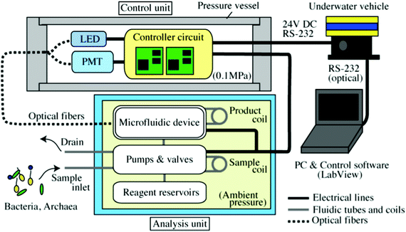 |
| | Fig. 1 Schematic overview of IISA-Gene. The analysis unit, whose components are immersed in fluorinated oil, is connected to the control unit enclosed in a pressure vessel via underwater cables and optical fibers. The IISA-Gene is connected to the underwater vehicle, which acts as the power supply (24 V DC), and it is controlled by a remote operator on a surface vessel using a PC. | |
The analysis unit is composed of the microfluidic device, pumps, valves, and tubing (see supplementary Fig. 1, ESI†). A miniature solenoid or DC motor actuated pump is used for the sample intake. Stepping motor actuated miniature syringe pumps are used to supply the reagents into the microfluidic device. Solenoid actuated valves mounted on a PMMA fluidic manifold are connected to pumps and a microfluidic device for reagent switching. All reagents are stored in reagent tanks that have indirect pumping capability. The analysis unit is enclosed in a metal box and immersed in fluorinated oil for electrical insulation and pressure compensation. Hence, all fluidic operations and molecular biological processes are performed under ambient hydrostatic pressure during the operation in ocean environments. In general, a complicated valve system for sampling operations from high pressure to low (atmospheric) pressure leads to an increase in apparatus size. Therefore, in order to simplify the sampling mechanism, we adopted a strategy to perform all the analytical procedures under an ambient (high) pressure for the IISA-Gene system. The pair of glass optical fibers is fixed on the microfluidic device for optical detection of fluorescently stained PCR products.
The control unit includes a cylindrical pressure vessel with a controller circuit for controlling the analysis unit. A PC on a surface vessel is connected to the controller circuit using the RS-232 data communication format via optical fiber cables.
The LED light source and PMT for the detection of fluorescence from the PCR products are also enclosed in the pressure vessel as well as the controller circuit. One of the two glass optical fibers is connected to the LED light source to provide excitation light to the microfluidic device. The PMT in the pressure vessel is connected to another optical fiber to deliver the fluorescence from the PCR products in the microfluidic device. The analysis unit and control unit are fixed on a metal frame box and mounted on underwater platforms, such as an underwater vehicle, for in situ operation.
2.2 Analysis unit
2.2.1 Microfluidic device.
The core functional element of the IISA-Gene is the polydimethylsiloxane (PDMS)–glass hybrid microfluidic device, which can perform microbial cell lysis, DNA purification, PCR and optical detection of PCR products (Fig. 2). The microfluidic device for the IISA-Gene is composed of a PDMS microfluidic chip and a glass-based temperature control chip. A microchannel (220 μm deep) was fabricated on the planar PDMS chip. The design of the microchannel is schematically shown in Fig. 3 along with the patterns of the heaters and temperature sensors. The microfluidic device has four main operational parts for cell lysis, DNA purification, flow-through PCR, and optical detection. The microchannel is terminated by three inlet ports for chemicals or samples and two outlet ports for wastes and PCR products. A cell lysis buffer is supplied from an upstream port and mixed with a seawater sample that is supplied from a neighboring downstream sample port. Microbial cells in the sample are lysed as they pass through the cell lysis part (200 μm wide, 971 mm long, 22 μL in volume). Subsequently, the cell lysate is supplied to the DNA purification part, holding approximately 5 mg of glass beads (30 to 50 μm in diameter) in a 1 mm wide and 11 mm long microchannel terminated by a narrow microchannel (20 μm wide). Because the cell lysis buffer contains guanidium thiocyanate as a chaotropic agent, genomic DNA is adsorbed onto the glass beads packed in the DNA purification part. After processing 500 μL of the seawater sample, the cell lysis part, DNA purification part, and the glass beads are washed with a washing buffer supplied from the chemical port. During the cell lysis and the washing step, all wastes are drained from the waste port. Subsequent to the washing process, purified and concentrated DNA is eluted directly into a PCR mixture that is supplied from a PCR mix inlet port. The PCR mixture containing template DNA is introduced into the flow-through PCR part. The PCR part is a long serpentine microchannel (100 μm wide, 3050 mm long, 69 μL in volume) that is used to perform 30 thermal cycles in a flow-through manner with a residence time ratio of 8![[thin space (1/6-em)]](https://www.rsc.org/images/entities/char_2009.gif) :2:2:3:10 for the initial denaturation step, 30 cycles of denaturation, annealing, extension, and final extension steps, respectively. The flow-through (or continuous flow) PCR17–20 offers the advantages of simplicity of temperature and fluid control; therefore, it is suitable for in situ instrumentation. Before the PCR mixture reaches the outlet port for PCR products after 30 thermal cycles, it passes through the optical detection part. The microchannel in the optical detection part has a diamond-like geometry in order to increase the path length of light for the SYBR green based detection of PCR products. Two microgrooves used to fix the optical glass fibers (200 μm in core diameter, 220 μm in clad diameter) are separated from the fluidic microchannel by flat wall structures (20 μm wide) of PDMS.
:2:2:3:10 for the initial denaturation step, 30 cycles of denaturation, annealing, extension, and final extension steps, respectively. The flow-through (or continuous flow) PCR17–20 offers the advantages of simplicity of temperature and fluid control; therefore, it is suitable for in situ instrumentation. Before the PCR mixture reaches the outlet port for PCR products after 30 thermal cycles, it passes through the optical detection part. The microchannel in the optical detection part has a diamond-like geometry in order to increase the path length of light for the SYBR green based detection of PCR products. Two microgrooves used to fix the optical glass fibers (200 μm in core diameter, 220 μm in clad diameter) are separated from the fluidic microchannel by flat wall structures (20 μm wide) of PDMS.
 |
| | Fig. 2 PDMS–glass hybrid microfluidic device for the IISA-Gene. The PDMS microfluidic chip is bonded with the glass-made temperature control chip. Metallic electrical contacts are installed on the electrical contact pads. A pair of the optical fibers is fixed in the microgrooves. | |
 |
| | Fig. 3 Schematic illustration of microfluidic device for IISA-Gene. A serpentine microchannel is placed on the 6 heater and a temperature sensor pair. Rectangular thin film heaters (Thin Cr layer, approx. 100 Ω) are configured in parallel to produce three temperature zones for flow-through PCR. Temperature sensors (Pt RTD that has approx. 2.5 kΩ) are aligned with heaters on the opposite face of the glass substrate. External connections of heaters and temperature sensors were made through square shaped contact pads on the edge of the glass substrate. Dotted squares represent the areas used as contact pads for electrical connections. | |
The temperature control chip was integrated with the PDMS microfluidic chip in order to conduct temperature control during the cell lysis and PCR steps. A glass-based temperature control chip has 6 thin film temperature sensors (platinum) each of which is paired with a heater (chromium). The temperature sensors are configured in parallel on the topside (the PDMS channel side) of the glass substrate (50 x 76 mm, 1 mm thick). The 50 μm-wide folded Pt lines (approx. 30 mm-long) working as resistance temperature detectors (RTD) are connected to contact pad patterns on their ends. The Cr thin film heaters are located on the backside of the glass substrate. When a constant voltage is applied to the parallel rectangular heaters, two-dimensional temperature distributions are regulated by the balance of heating and cooling from the surface and the edge of the glass material. Hence, the central part of each heater has a wider pattern compared to both of its edges, which means that there is higher Joule heating at the narrower edge regions of the heaters due to higher resistances, resulting in a uniform parallel temperature distribution on the microfluidic device.
2.2.2 Microfabrication.
The PDMS (SYLGARD 184, Dow Corning Toray Co., Japan) microchannel chip was fabricated by a conventional replica molding method using a negatively patterned mold master made of SU-8 (SU-8 2100, Microchem Co., USA) on a silicon wafer. The bulk thickness of the PDMS microfluidic chip is 2 mm. Through holes (2 mm in diameter) were opened manually using a disposable biopsy punch (Kai industries Co. Ltd., Japan).
Platinum RTD temperature sensors and chromium thin film heaters were patterned on the top and bottom sides of the glass substrate (50 × 76 mm, 1 mm thick), respectively, by wet etching methods. Subsequent to the patterning of the heaters and temperature sensors, the upper (PDMS channel side) surface was coated with a spin-on glass (OCD T-7 12000-T, Tokyo Oka Kogyo, Japan) for electrical insulation. Finally, uncured PDMS was spin coated on the temperature control chip and cured. The PDMS microchannel chip and completed temperature control chip were permanently bonded together after exposure to oxygen plasma using a reactive ion etching (RIE) machine (SAMCO Co., Japan). 5 mg of glass beads (30–50 μm in diameter, Polysciences Inc., USA) suspended in sterilized water were introduced manually from the PCR mix inlet port prior to assembly of the whole system. Finally two optical glass fibers (200 μm core diameter, 220 μm clad diameter, F-MCC-T, Newport, USA) were placed in the microgrooves in the optical detection part for fluorescence detection.
2.2.3 Pumps, valves, and tubing.
A connection diagram of the pumping components is shown in supplementary Fig. 2 in the ESI†. The analysis unit has two stepping motor actuated syringe pumps (pump 1 and 2; LPVX0502250B PEEK, 1250 μL pumping/stroke, The Lee Co., USA) for precision pumping of reagents and samples, as well as a solenoid actuated pump or DC motor based annular gear pump (pump 3; NRP-500P, Takasago Electric Inc., Japan or mzr-2521, HNP Mikrosysteme GmbH, Germany) for sample intake. The pumping system is simplified by use of the stepping motor actuated syringe pumps for reagent pumping because no flow-rate sensor is necessary for the control of reagent flow rates. The solenoid actuated pump for sample intake was replaced by a DC motor actuated annular gear pump for the second field trial of IISA-Gene in order to improve the reliability on sample intake. Solenoid actuated 2- and 3-way (EXV-2R-6MHF-1, ECV-3-MFFH-2, Takasago Electric Inc.) valves were used for fluid switching. The use of tubes and connectors was circumvented by mounting all of solenoid valves on a PMMA manifold. The cell lysis buffer, DNA Away™, and PCR mixtures were pumped indirectly using reagent tanks (2 mL volume) that have a PDMS membrane as a liquid separator. Autoclaved 1x PCR buffer (as wash buffer) was used as the driving fluids for all of the indirect pumping. Teflon FEP (fluorinated ethylene propylene) tubes (1/16” OD, 0.02–0.03” ID, Upchurch Scientific, USA) were used for all fluidic connections and to configure the tube coils. The tube coils were used to store sample (500 μL coil volume), segmentation oil (200 μL), and PCR products (1 mL). Waste from the waste port and PCR product port bypass the tube coil for PCR products and is stored in a waste bag. A 5 cm long tube comes out of the metal box of the analysis unit for sample intake. The analysis unit with the microfluidic device and pumping components are filled with fluorinated oil (Fluorinert FC-43, 3M, USA).
2.3 Control unit
The control unit consists of an electrical circuit as the controller circuit, optical components, and a pressure vessel in which the components are enclosed. The controller circuit can perform on/off control of six heaters by comparing the temperatures (resistances of RTDs) measured by on-chip temperature sensors with set values from a PC. The controller circuit also controls all the pumping components. The controller circuit includes a stepping motor driver enabling micro-step driving of stepping motors (IM481H Plus, Schneider Electric Motion USA, 10 nL pumping/pulse signal) for high precision pumping. The optical components consist of the LED light source (LXHL-NB98, Phillips Lumileds Lighting Co., USA, 490 nm peak emission), and the PMT (H5784, Hamamatsu, Japan). A band-pass filter (482/35, Semrock Inc., USA) and a collimate lens unit (F810SMA-543, Thorlabs Inc., USA) are installed between the LED and the optical fiber. The PMT is equipped with a second band-pass filter (536/40, Semrock) combined with a collimate lens (74-UV, Ocean Optics Inc., USA) that are used for filtering and focusing the fluorescence from the PCR products. Underwater electrical connectors and feed-through fiber connectors are attached to the cylindrical titanium alloy pressure vessel (104 mm outer diameter, 380 mm long, 6000 m depth rating). One of the electrical connectors is used for the power supply (DC 24V) and communication with a user PC.
2.3 Reagents
The cell lysis buffer was prepared as described by Boom et al.21 1× PCR buffer for Taq DNA polymerase used in this study (Takara Taq Hot Start Version R007A, Takara Bio Inc., Japan) was used as the washing buffer. The use of PCR buffer as a washing buffer instead of alcohols prevents PCR inhibition when the washing buffer contaminate the PCR mixture during an elution process. The PCR mixture contains 1× PCR buffer, dNTPs (0.2 mM each), Taq DNA polymerase (0.075 U/μL), forward and reverse oligonucleotide primer (0.5 μM each), and 2x SYBR Green I dye (Invitrogen, USA). A primer pair for 16S rRNA gene (341f–926r)22 was used to amplify the eubacterial universal gene. Primer pairs for particulate methane monooxygenase (pMMO) gene (A189–682r23 or pmof1-pmor24) were used for the functional gene detection trial. Adsorption of the PCR mixture contents, such as Taq DNA polymerase onto the PDMS surface was prevented by adding 5% (vol/vol) of Tween 20 (ICN Biomed. Inc., USA) to the PCR mixture. DNA Away™ (Molecular BioProducts Inc., USA), which is a commercially available solution for destroying DNA molecules,25 is used without dilution to remove DNA contamination in the system. Mineral oil (Nacalai Tesque Inc., Japan) is used as the oil for segmentation of the PCR products in the PCR product recovery tube.
2.4 Operation procedure
An operation procedure of the IISA-Gene is summarized in supplementary Fig. 3 in the ESI†. Ambient seawater samples are continuously introduced into the sample coil by the solenoid or DC motor actuated pump without flow-rate control for a duration of 2 min. Here, the sample coil and peripheral tubing are rinsed out by a sufficient amount (approx. 10 mL) of sample seawater to avoid crossover contaminations. Subsequently, both the sample and the cell lysis buffer stored in a tank are simultaneously pumped into the microfluidic device at a flow-rate of 750 μL h−1 each (1500 μL h−1 in total, 40 min). Microbial cells are lysed upon passing through the cell lysis part, which is maintained at 50 °C. In the DNA purification part containing the glass beads, genomic DNA is captured on the surfaces of the glass beads. Following the cell lysis and DNA capture processes, the heater power is switched off and cell lysis buffer is replaced by the washing buffer, supplied from the chemicals inlet port (1000 μL h−1, 20 min). Waste is drained from the waste port during the cell lysis, DNA purification, and washing processes. Subsequently, the PCR mix is supplied to the DNA purification part and captured DNA is eluted into the PCR mix over the duration of 2 min by raising the temperature up to 98 °C. The PCR mix with template DNA is introduced into the microchannel for flow-through PCR and 30 thermal cycles are performed at a flow-rate of 90 μL h−1 (46 min for 30 cycles). The temperature conditions for the PCR were set as follows for both 16S rRNA gene and pMMO gene amplification: 98 °C, 50 °C and 72 °C for denaturation, annealing and extension, respectively. Each PCR process is continued for up to 90 min to confirm whether or not delayed increase of the fluorescence signal is observed. After the PCR process, amplified products are recovered into the product coil and segmented by mineral oil (4 min). The microchannel is treated with 100 μL of DNA Away™ prior to the successive operation (3 min). Finally, DNA Away™ is thoroughly removed by rinsing with 200 μL of the washing buffer (6 min). The total time for an entire analysis sequence is about 120 to 165 min depending on the elapsed time for PCR. Recovered PCR products are kept for subsequent analysis by conventional gel electrophoresis.
2.5 Evaluation
The performance of the IISA-Gene system was evaluated using simulated natural samples comprised of model microbial cells. Freeze-stocked methanotroph (Methylosinus trichosporium OB3b) cells were re-suspended in sterilized and filtered artificial seawater (Daigo's artificial seawater SP for marine microalgae medium, Nihon Pharmaceutical Co. Ltd., Japan) in concentrations of 1 × 10³ and 104cells/mL. Artificial seawater without microbial cells was used as a negative control sample.
2.6
In situ evaluations
The completed IISA-gene system was operated at two different hydrothermal sites in the Okinawa Trough, Japan using an ROV “HYPER-DOLPHIN” (Japan Agency for Marine-Earth Science and Technology: JAMSTEC, Japan) in June 2008 (Dive #853 in the Hatoma Knoll26,27) and September 2009 (#1062 in the Iheya North site27). IISA-Gene was fixed on a payload-bay and connected to the ROV using one of the underwater cables (Fig. 4). During dive #853, IISA-Gene was operated a few meters above an active hydrothermal vent at a depth of 1471 m. Seawater samples were collected twice at the same position for 16S and pMMO gene detection, respectively. During dive #1062, an attempt was made to only amplify the 16S rRNA gene because of the limited operation time for the ROV. The sample was collected once in the immediate vicinity of the hydrothermal activity (1004 m deep). During amplification of the 16S rRNA gene, the PCR process was interrupted once due to a temporary failure of the power supply from the ROV. After recovery of the power supply, the PCR process was re-started immediately. For both field trials, seawater samples for on-board analysis were collected using water samplers attached to the ROV. 500 μL portions of the collected water samples were manually processed on-board using the same chemicals and method as the IISA-Gene.
 |
| | Fig. 4 The IISA-Gene mounted on the ROV “HYPER-DOLPHIN” (dive# 853). The cruise for HYPER-DOLPHIN operation was conducted by a research vessel “Natsushima” (JAMSTEC). | |
3. Results and discussion
3.1 Desktop evaluation
The results of the 16S rRNA gene amplification, performed by IISA-Gene from 500 μL of artificial seawater containing 1 × 10⁴cells mL−1 of M. trichosporium (5 × 10³cells in total) is shown in Fig. 5, along with the negative control data. The fluorescence intensity clearly increased from the background level at around 60 min and reached a plateau. On the other hand, the 1 × 10³cells mL−1 sample (data not shown) and negative control showed no signal increase within 75 min of the PCR process. From these results, the detection limit of IISA-Gene is determined to be between 1 × 10³ to 104cells mL−1 and thus a sample containing 5 × 10³ microbial cells should give a positive result in the detection of the 16S rRNA gene. Although the expected elapsed time for fluorescence signal increase is about 40 min using a slow rate condition of 90 μL h−1 (when considering the total volume of the microchannel for 30 cycles of PCR (69 μL)), a signal increase was observed at 60 min. This delay is thought to be due to pressure buffering caused by the compression of air bubbles in the pumping components or expansion of the PDMS microfluidic device and/or tubing by the pressurization for pumping. Therefore, additional PCR time should be employed when a negative result is obtained after the calculated time for 30 cycles of PCR has elapsed in order to ensure the accuracy of the results.
 |
| | Fig. 5 Results of 16S rRNA gene amplification from 1 × 10⁴cells mL−1 of M. trichosporium cells using IISA-Gene. PMT voltage was recorded every 2 s and 40 s averaged data are shown. | |
3.2
In situ trial operations
During two sets of in situ trial operations, IISA-Gene was successfully operated remotely in deep-sea environments. The results of operations during dive #853 in the Hatoma Knoll hydrothermal site shows that fluorescence intensity started to increase at around 45 min after the start of the PCR process for both the 16S rRNA gene and pMMO gene. Subsequently, a sharp increase in the fluorescence intensity was observed for the 16S rRNA gene, whereas pMMO showed no distinct increase (Fig. 6). This result indicates that there were more than 1 × 10⁴cells of Eubacteria in the analyzed hydrothermal fluid, whereas methane-oxidizing bacteria were either absent or present in numbers below the detection limit. Data obtained from the onboard analysis using seawater, which was sampled at the same position as the IISA-Gene operation, were consistent with these results. The fluorescence signal of 16S rRNA gene amplification reached a maximum within 5 min after the intensity started to rise, and declined once before reaching a steady state. This may be because most of the template DNA was eluted into the initial fraction of the PCR mixture. The subsequent signal decrease may correspond to the PCR result with a lower template DNA concentration. The second increase of the fluorescence signal and the plateau is assumed to be derived from the PCR product that was amplified under apparently slower thermal cycle conditions than the expected 46 min retention time for 30 cycles due to a parabolic flow profile in the microchannel. Recovery of the PCR product was not successfully carried out during this field operation because of a malfunction of the solenoid actuated valve.
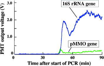 |
| | Fig. 6 Result of the 16S rRNA gene and pMMO gene amplification during dive #853 in the Hatoma Knoll hydrothermal site, Okinawa, Japan. | |
During dive #1062, signal increase was observed at around 35 min after the start of PCR for the 16S rRNA gene (Fig. 7). After a temporary interruption, the fluorescence signal recovered intensity within approximately 30 min after the re-start of PCR. The amplified PCR product was recovered in the product coil for further analysis (see supplementary Fig. 4 in the ESI†). The electrophoresis results (Fig. 8) indicate that the sizes of the PCR products from IISA-Gene are the same as those of the 16S positive control (about 585 bp). However, smears, nonspecific products, and primer dimers were observed for the IISA-Gene PCR products. Hence, although the major fluorescence signal is emitted from the specific PCR products, a portion of the fluorescence signals may be emitted from the unwanted products. These observations suggest that further optimization on the thermal cycling conditions is necessary for highly reliable in situgene analysis.
 |
| | Fig. 7 Result of the 16S rRNA gene amplification during dive #1062 in the Iheya North hydrothermal site, Okinawa, Japan. During the PCR, the amplification process was interrupted once by a temporary unavailability of electricity supply from the ROV. | |
 |
| | Fig. 8
Electrophoresis results of the recovered PCR product amplified in situ during dive #1062 in the Iheya North hydrothermal site. (1) 16S negative control, (2) pMMO negative control, (3) Blank, (4) 16S positive control, (5) pMMO positive control, (6) 100 bp DNA ruler, (7) Blank, (8–13) The recovered PCR products. Approximately 60 μL of the recovered PCR products were separated into 10 μL fractions for application to the gel. Thr fraction in lane 13 corresponds to the first PCR product obtained from the microfluidic device. Visible bands of PCR products were observed from lane 12. Time course series of 10 μL PCR products were applied to the gel from lane 13. | |
4. Conclusion
In the present study, a totally integrated in situ analyzer for microbial gene detection, “IISA-Gene,” was developed and evaluated in a laboratory and in actual deep-sea environments. The result of evaluation using model cells indicated that the detection limit of IISA-Gene is 1 × 10³ to 104cells mL−1, and which corresponds to the presence of 5 × 10³ microbial cells in a sample. In situ operations of the completed analyzer in deep-sea environments resulted in successful amplification of the 16S rRNA gene fragments from seawater samples collected near hydrothermal sites and the recovery of PCR products. pMMO gene amplification did not occur because of the absence of a detectable number of methanotrophs in situ. Owing to the limited observation time, in situgene analyses could be performed only once or twice during a dive of the underwater vehicle carrying the IISA-Gene. This warrants future studies on the sensitivity and processivity of the IISA-Gene. Nevertheless, utilization of the unprecedented in situ analyzer with microfluidic technology will enable us to achieve spatiotemporally resolved profiling of microbial ecosystems in ocean environments with a new methodology that is independent of sampling operations and contamination risks. Use of a microfluidic device made of PDMS and glass is possible, even in high hydrostatic conditions. It was confirmed that all components of the analysis unit could be used in the extreme conditions via immersion in fluorinated oil. The knowledge established here can be widely applied to the development of novel automated apparatus based on microfluidic technology.
Acknowledgements
The authors are grateful to the crew of the R/V Natsushima and the operating team of ROV HYPER-DOLPHIN (JAMSTEC) for their helpful assistance during the scientific cruise NT08-11 and NT09-17. This work was funded by a grant-in-aid for scientific research (S) from the Ministry of Education, Culture, Sports, Science, and Technology (MEXT), Japan. The authors would also like to extend our gratitude to the Engineering Advancement Association of Japan (ENAA) for their support.
References
- F. Niehaus, C. Bertoldo, M. Kähler and G. Antranikian, Appl. Microbiol. Biotechnol., 1999, 51, 711–729 CrossRef CAS.
- M. Ferrer, A. Beloqui, K. N. Timmis and P. N. Golyshin, J. Mol. Microbiol. Biotechnol., 2009, 16, 109–123 CrossRef CAS.
- C. Scholin, G. Doucette, S. Jensen, B. Roman, D. Pargett, R. Marin III, C. Preston, W. Jones, J. Feldman and C. Everlove, Oceanography, 2009, 22, 158–161 CrossRef.
- D. Fries, J. Paul, M. Smith, A. Farmer, E. Casper and J. Wilson, Microsc. Microanal., 2007, 13, 514–515 CrossRef.
- D. Greenfield, R. Marin III, S. Jensen, E. Massion, B. Roman, J. Feldman and C. Scholin, Limnol. Oceanogr.: Methods, 2006, 4, 426–435 CrossRef.
- T. Chapin, H. Jannasch and K. Johnson, Anal. Chim. Acta, 2002, 463, 265–274 CrossRef CAS.
- H. Jannasch, K. Johnson and C. Sakamoto, Anal. Chem., 1994, 66, 3352–3361 CrossRef CAS.
- D. Thouron, R. Vuillemin, X. Philippon, A. Lourenço, C. Provost, A. Cruzado and V. Garçon, Anal. Chem., 2003, 75, 2601–2609 CrossRef CAS.
- J. Khandurina, T. E. McKnight, S. C. Jacobson, L. C. Waters, R. S. Foote and J. M. Ramsey, Anal. Chem., 2000, 72, 2995–3000 CrossRef CAS.
- C. J. Easley, J. M. Karlinsey, J. M. Bienvenue, L. A. Legendre, M. G. Roper, S. H. Feldman, M. A. Hughes, E. L. Hewlett, T. J. Merkel, J. P. Ferrance and J. P. Landers, Proc. Natl. Acad. Sci. U. S. A., 2006, 103, 19272–19277 CrossRef CAS.
- E. Morganti, C. Collini, C. Potrich, C. Ress, A. Adami, L. Lorenzelli and C. Pederzolli, J. Sens., 2011, 2011, 1–7 Search PubMed.
- K.-Y. Lien, Y.-H. Chuang, L.-Y. Hung, K.-F. Hsu, W.-W. Lai, C.-L. Ho, C.-Y. Chou and G.-B. Lee, Lab Chip, 2010, 10, 2875 RSC.
- P. Liu, S. H. I. Yeung, K. A. Crenshaw, C. A. Crouse, J. R. Scherer and R. A. Mathies, Forensic Sci. Int.: Genet., 2008, 2, 301–309 CrossRef.
- P. Liu, T. S. Seo, N. Beyor, K.-J. Shin, J. R. Scherer and R. A. Mathies, Anal. Chem., 2007, 79, 1881–1889 CrossRef CAS.
- E. T. Lagally, J. R. Scherer, R. G. Blazej, N. M. Toriello, B. A. Diep, M. Ramchandani, G. F. Sensabaugh, L. W. Riley and R. A. Mathies, Anal. Chem., 2004, 76, 3162–3170 CrossRef CAS.
- G. V. Kaigala, V. N. Hoang, A. Stickel, J. Lauzon, D. Manage, L. M. Pilarski and C. J. Backhouse, Analyst, 2008, 133, 331–338 RSC.
- M. Kopp, A. Mello and A. Manz, Science, 1998, 280, 1046 CrossRef CAS.
- H. Nakano, K. Matsuda, M. Yohda, T. Nagamune, I. Endo and T. Yamane, Biosci., Biotechnol., Biochem., 1994, 58, 349 CrossRef CAS.
- M. Curcio and J. Roeraade, Anal. Chem., 2003, 75, 1–7 CrossRef CAS.
- T. Fukuba, T. Yamamoto, T. Naganuma and T. Fujii, Chem. Eng. J., 2004, 101, 151–156 CrossRef CAS.
- R. Boom, C. Sol, M. Salimans, C. Jansen, P. Wertheim-van Dillen and J. Van der Noordaa, Journal of clinical microbiology, 1990, 28, 495 CAS.
- C. Kato, L. Li, J. Tamaoka and K. Horikoshi, Extremophiles, 1997, 1, 117–123 CrossRef CAS.
- J. Murrell, I. McDonald and D. Bourne, FEMS Microbiol. Ecol., 1998, 27, 103–114 CrossRef CAS.
- Y. Cheng, J. Halsey, K. Fode, C. Remsen and M. Collins, Applied and environmental microbiology, 1999, 65, 648 CAS.
- B. Kemp and D. Smith, Forensic Sci. Int., 2005, 154, 53–61 CrossRef CAS.
- S. Tsuchida, K. Watanabe, J. Ishibashi, H. Miyake, H. Watabe, T. Yamaguchi, T. Kitajima, A. Nakano, M. Matsumura and H. Watanabe, JAMSTEC Journal of Deep Sea Research, 2000, 17, 34–42 Search PubMed.
- K. Takai, F. Inagaki, S. Nakagawa, H. Hirayama, T. Nunoura, Y. Sako, K. Nealson and K. Horikoshi, FEMS microbiology letters, 2003, 218, 167–174 CAS.
|
| This journal is © The Royal Society of Chemistry 2011 |
Click here to see how this site uses Cookies. View our privacy policy here.