DOI:
10.1039/C0NR00601G
(Paper)
Nanoscale, 2011,
3, 272-279
Highly monodisperse Cu- and Ag-based bimetallic nanocrystals for the efficient utilization of noble metals in catalysis†
Received
17th August 2010
, Accepted 13th September 2010
First published on 29th October 2010
Abstract
Highly monodisperse Cu- and Ag-based bimetallic noble metal nanocrystals (BNMNs) with diameter 2–7nm have been synthesized. The synthesis employs a successive reduction process by using inorganic metal salts as precursors at a low temperature (∼110 °C). HRTEM, XPS and XRD analytical techniques were applied for the structural analysis of BNMNs. Catalytic activity investigation (CO oxidation) over different supports (silicate nanotubes and CeO2 nanoparticles) shows that BNMNs have identical and even enhanced performance over pure noble metal nanocrystals with similar size and size distribution, which proves that these BNMNs can significantly reduce the amount and thus make full use of noble metals in catalysis.
Introduction
Noble metal nanostructures have attracted extensive research attention due to their unique physical and chemical properties and potential applications in fields such as catalysis, bio- or chemical sensors and nanoelectronics.1–5 Noble metals such as Pt, Pd and Au are rare, so making efficient use of noble metal nanomaterials is highly desired and some approaches have been developed, such as the controlled synthesis of special morphology noble metal with more active faces6or depositing the noble metal on a support to enhance noble metal utilization.7 Bimetallic noble metal nanocrystals (BNMNs), especially those with other transition metals introduced, might greatly enhance the efficient use of noble metals and simultaneously some of their specific properties, which are not just the addition of the two properties of the component metals.8–13 Several methods have been explored for the fabrication of BNMNs with alloy or core-shell structures, such as the polyol process,14thermal decomposition of organometallic precursors,15,16redox-transmetallation processes17 and directly reduction of inorganic metal salts in solution.18–22 Generally, simultaneous reduction processes were adopted for alloyed BNMN structures and sequential reduction processes were adopted for core-shell BNMNs. However, most BNMNs obtained suffer from unsatisfactory size, broad size distribution and non-uniform shape. Considering that many chemical and physical properties of noble metals strongly depend on their size,23–25 the controllability of size is highly important.
Herein we demonstrate a general strategy for the synthesis of Cu- and Ag-based BNMNs with smaller size and narrow size distribution using inorganic metal salts as precursors at a low temperature (∼110 °C). Cu- and Ag-based BNMNs were synthesized on the basis of a successive reduction process, which was usually adopted for core-shell structure BNMNs. Cu or Ag were chosen because they are less expensive than noble metals; on the other hand, the lower redox potential favors the noble metal depositing on their surface. Catalytic activity investigation (CO oxidation) over different supports (silicate nanotubes and CeO2 nanoparticles) shows that BNMNs have identical and even enhanced performance over pure noble metal nanocrystals with similar size and size distribution, which proves that these BNMNs can significantly reduce the amount and thus make full use of noble metals in catalysis.
Experimental
Dioctadecyldimethylammonium bromide (DODA, 99%) and tetraoctylammonium bromide (TOAB, 99%) were purchased from Acros Organics. H2PtCl6·6H2O, HAuCl4·4H2O, and PdCl2 were purchased from Grikin Advanced Materials Co., Ltd. The rest of the chemicals were purchased from Beijing Chemical Reagent Company. All chemicals were of analytical grade and were used as received without further purification. Deionized water was used throughout the experiment.
Phase-transformation
The noble metal ions were transferred into toluene solution by a phase transformation process.26 In a typical procedure, an aqueous solution of noble metal precursor (5 mL, 30 mM) contained H2PtCl6 (or HAuCl4, PdCl2) was mixed with a solution of TOAB in toluene (10 mL, 60 mM) under vigorously stirring for 10 min. The organic phase was separated to make a stock solution with 15 mM concentration.
Preparation of Cu-based BNMNs
The Cu-based BNMNs were typically prepared as follows. 30 mg of cupric acetate and 120 mg of DODA were added into 10 mL of toluene, and the mixture was heated up to boiling under continuous magnetic stirring to form a dark green solution. A freshly prepared aqueous solution of NaBH4 (36 μL, 9.4 M) was injected under vigorous stirring. The dark green solution turned dark brown within a minute indicating the formation of Cu cores,27 of about 1.5 ± 0.2 nm diameter. Next, 36 μL of dodecanethiol (DT) was added to stabilize the Cu cores. Then 3 mL of stock solution of noble metal precursor (Cu![[thin space (1/6-em)]](https://www.rsc.org/images/entities/char_2009.gif) :noble metal = 1:0.3, molar ratio) was quickly added into the dark brown Cu colloidal solution. After 5 min, further NaBH4 (36 μL, 9.4 M) solution was added and heating was stopped. After cooling to room temperature, the product was separated by centrifugation and washed with 30 mL ethanol by a repetitive dispersion/precipitation cycle. The product was redispersed in toluene.
:noble metal = 1:0.3, molar ratio) was quickly added into the dark brown Cu colloidal solution. After 5 min, further NaBH4 (36 μL, 9.4 M) solution was added and heating was stopped. After cooling to room temperature, the product was separated by centrifugation and washed with 30 mL ethanol by a repetitive dispersion/precipitation cycle. The product was redispersed in toluene.
Stability of Cu–Pt and Cu–Au BNMNs
An aliquot amount of BNMNs was first dried at 80 °C for 1 h and then thermally annealed at 300 °C for 30 min and 400 °C for 6 h in the air. After thermal treatment, the powders were used to further XRD analysis.
Supported noble metal catalysts
Mg3Si2O5(OH)4
nanotubes, chosen as supports due to their well-defined shape, large surface areas and highly thermal stability, were prepared as reported previously.28 The noble metal catalysts including Cu–Pt BNMNs, Ag–Pt BNMNs and pure Pt nanocrystals were deposited on Mg3Si2O5(OH)4 nanotubes by a general method for oxide-supported metal nanoparticle catalysts reported by Stucky,29 which is also suitable for a Mg3Si2O5(OH)4 support. In a typical process, the calculated Mg3Si2O5(OH)4 powder was added to 20 mL of toluene solution of noble metal catalysts with a concentration of 1 mg mL−1. The suspension was stirred in the air at room temperature for 1 h to prepared a mixture of 5% noble metal catalyst/Mg3Si2O5(OH)4 nanotubes. It was observed that the white Mg3Si2O5(OH)4 powder turned black after stirring, which indicated loading of the noble metal catalysts. After centrifugation, the black powder was dried at 80 °C for 1 h and annealed at 300 °C for 30 min. For comparison, CeO2 nanoparticles30 were also applied to support noble metal catalysts by the same way depicted as above.
Catalytic activity measurements
Catalytic activity of supported noble metal catalysts (5 wt% noble metal loading) for CO oxidation was measured using a conventional quartz tubular reactor (i.d. 6 mm; length 300 mm) at atmospheric pressure under steady-state conditions. The temperature was measured by a thermocouple placed near the sample. The reagent gas mixture (5% CO and 95% air) was fed over 0.2 g catalyst at a flow rate of 100 mL min−1 with a contact time of 2 × 10⁻⁵ h. The CO oxidation reaction was stabilized for 15 min, and the outlet products were measured with gas chromatography (GC112A Gas Chromatograph).
Characterization
The size and morphology of the core-shell nanocrystals were probed by transmission electron microscopy (TEM; JEOL JEM 1200EX working at 100 kV), and high-resolution transmission electron microscopy (HRTEM; Tecnai G2 F20 S-Twin working at 200kV) equipped with an X-ray energy dispersive spectrometer (EDS). TEM samples were prepared as follows: a small amount of obtained product was dispersed in toluene. One drop of the resulting suspension was deposited on carbon-coated Mo grids, and the solvent was then evaporated at room temperature in air. X-ray photoelectron spectra (XPS) were recorded on a PHI Quantera SXM spectrometer using monochromatic Al-Kα X-ray sources (1486.6 eV). All XPS data was acquired at a nominal photoelectron takeoff angle of 45°. The binding energies of the peaks obtained were made with reference to the binding energy of the C 1s line, set at 284.8 eV. The spectrum was fitted using an 80% linear combination of Gaussian–Lorentzian profiles. All samples were deposited onto Si substrates, forming a thin film of several monolayers. UV-vis absorption spectra were measured on a Hitachi U-3010 spectrophotometer with a 1 cm quartz cuvette. Solutions were typically prepared at a concentration of 0.1 mg mL−1 in toluene. An inductively coupled plasma optical emission spectroscopy (2RIS Intrepid II XSP ICP-OES) was used to measure the content of BNMNs. The samples were dissolved in concentrated HCl/HNO3 (3:1 v/v). Powder X-ray diffraction (XRD) measurement of the products was carried out on a Bruker D8 Advance X-ray powder diffractometer with Cu-Kα radiation (λ = 1.5418 Å).
Results and discussion
Composition and structure analysis of Cu–Pt BNMNs
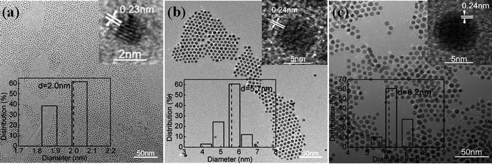
Cu–Pt BNMNs were synthesized on the basis of a successive reduction process, which is usually adopted for core-shell structure BNMNs.26,27Fig. 1a shows the large domains of highly ordered arrays of Cu–Pt BNMNs obtained without any further size-selection processes. The obvious difference in the contrast indicates the nanocrystals are arranged in a three-dimensional (3D) structure by self-assembly. The magnified image (Fig. 1b) shows that the close-packed structure is stacked with component nanocrystals with uniform size and spacing of 2.0 nm. TEM image further indicates the monolayer array of Cu–Pt BNMNs with mean particle size of 2.0 nm (Fig. 1c). The inset HRTEM image shows a typical highly crystalline Cu–Pt BNMN, from which the plane spacing of 0.23 nm was measured, which corresponds to the fcc(111) lattice fringes of Pt.14HRTEM has been carried out to distinguish between the core-shell structures and alloy. However, for BNMNs with a thin shell, it is very difficult to distinguish the interface between the metal core and metal shell.14,17EDS spectrum (Figure S1a†) and ICP result (Table S1†) further confirm the presence of Pt and Cu elements with a ratio of 0.44 for Cu–Pt nanocrystals, but they also fail to provide strong evidence for the formation of a core-shell structure or alloy. XPS spectra (Fig. 2) at varying molar ratios of Pt to Cu were measured. With the increase of deposited Pt content, the signals of Pt 4f at 71.0 and 74.3 eV strengthened, accompanied by the gradually weakening of Cu 2p signals at 932.5 and 952.5 eV. The decrease in intensity of the Cu 2p signal is caused by the screening of deposited Pt. Zhao et al. also observed a similar change when the deposited Pt content increased on Au surfaces during the formation of AucorePtshellnanoparticles.7 The element ratios of Pt to Cu of Cu–Pt BNMNs obtained by XPS were further compared with ICP results (Fig. 2b). The ICP results are similar to the molar ratio of initial precursors, but all the element ratios obtained by XPS measurements are much higher than the ratios of initial precursors and ICP results. Above results demonstrate that Pt is rich in the surface part of the obtained nanocrystals, suggesting the formation of Cu-rich core–Pt-rich shell structure.
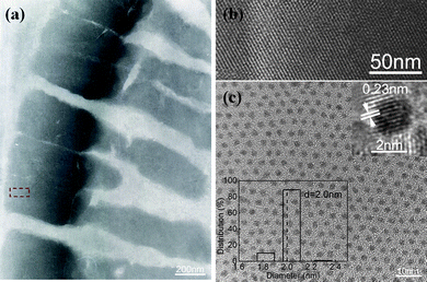 |
| | Fig. 1 (a,b) TEM and HRTEM images of Cu–Pt 3D superlattice, (c) TEM image of a monolayer Cu–Pt BNMNs. The insets in (c) show HRTEM image of a typical Cu–Pt nanocrystal (top), and size distribution histograms (bottom). The molar ratio of Cu to Pt is 1 to 0.3. | |
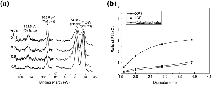 |
| | Fig. 2 (a) XPS spectra of Cu–Pt with varying molar ratios of Pt to Cu. (b) Intensity ratios of Cu 2p and Pt 4f and ICP results of Cu–Pt with varying molar ratio of Pt to Cu. | |
The XRD results provide more evidence of this. The XRD patterns of Cu–Pt BNMNs dried at 80 °C (Fig. 3a) reveal that the sample is composed of fccCu and fccPt, which is consistent with the XPS results and simultaneously excludes the possibility of an alloy. TEM measurements were carried out very carefully and completely over the whole TEM grid. The observed results indicate that the size of almost all the copper core is very uniform, which is about ∼1.5 nm before coating. But the domain size of the copper core in BNMNs calculated based on the XRD data using Scherrer equation, is larger than the size of the copper core observed by TEM analysis. The reason that the TEM and XRD data are not consistent may be attributed to the decrease of surface defects in the Cu cores. Beside the grain size, stress disturbances, crystallinity and the defects of crystals also contribute to the XRD HWFM in Scherrer equation. After coating with a noble metal, the surface defects of the copper core were reduced, which may result in the increase of effective grain size in XRD measurements. It is well known that Cu nanoparticles are susceptible to oxidation.31–33 However, in this study, the XPS and XRD results demonstrate that oxidation did not occur during the reaction and even thermal treatment at 80 °C and 300 °C in the air, which may be due to the effective protection of Pt shell (Fig. 3a, b). XRD pattern (Fig. 3c) of Cu–Pt BNMNs heated to elevated temperature (400 °C, 6h in the air) shows the formation of CuPt alloy and no copper oxide was detected yet. The restructuring phenomenon further suggests that the as-obtained product is not a physical mixture of Cu and Pt or alloy.
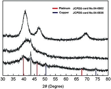 |
| | Fig. 3
XRD patterns of Cu–Pt BNMNs dried at 80 °C for 1h (a), annealed at 300 °C for 30min (b) and 400 °C for 6h (c). The molar ratio of Cu to Pt is 1 to 0.3 and the thermal treatment was carried out in the air. | |
Cu-based BNMNs
In addition to Cu–Pt BNMNs, other Cu-based Cu–Pt BNMNs or trimetallic nanocrystals including Cu–Pd, Cu–Au and Cu–Au–Pd can be synthesized by a similar procedure. Representative TEM images, HRTEM images, and size distribution histograms are shown in Fig. 4. Fig. 4a shows the TEM image of 2.0nm Cu–Pd BNMNs with narrow size distribution. The inset HRTEM of a typical Cu–Pd BNMN shows the lattice spacing of 0.23nm, which could be indexed as the fcc (111) plane of Pd. Cu and Pd signals are detected by EDS (Figure S1b) and Cu:Pd = 1:0.43 is supported by ICP result. It was found that all ICP results (Table S1) of Cu-based BNMNs are slightly less than the molar ratio of initial precursors (Cu: noble metal = 1:0.3). The reason is that a little amount of Cu entered water phase when NaBH4 aqueous solution was added, and thus was separated from the toluene solution of Cu-based BNMNs.
 |
| | Fig. 4
TEM images of Cu–Pd (a), Cu–Au (b), and Cu–Au–Pd nanocrystals (d). The insets in (a–c) show HRTEM images (top), and size distribution histograms (bottom). | |
Cu–Au BNMNs were also obtained by using gold precursor. The lattice distance measured by HRTEM (inset of Fig. 4b) is about 0.24nm, which is congruous with lattice parameter for fcc(111) plane of Au. Similar to Cu–Pt BNMNs, with the increase of deposited Au content, the signals of Au4f at 83.8eV and 87.8eV strengthened, accompanied by the gradually weakening of Cu2p signals at 932.5 and 952.5eV. The XPS peaks of Cu2p correspond well to the binding energy of metallic Cu (Fig. 5a), which indicates that oxidation did not occur during the reaction. The element ratios of Au to Cu of Cu–Au BNMNs obtained by XPS and ICP were also compared (Fig. 5b). The element ratios obtained by XPS measurement are higher than ICP results. These results indicate that the structure of Cu–Au BNMNs is similar to Cu–Pt BNMNs, and it is reasonably to believe that Au has successfully deposited on Cu core.
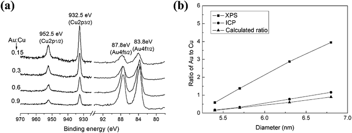 |
| | Fig. 5 (a) XPS spectra of Cu–Au with varying molar ratio of Au to Cu, (b) Intensity ratios of Cu2p and Au4f and ICP results of Cu–Au with varying molar ratio of Au to Cu. | |
XRD results further confirm that due to the protection of Au shell, Cu oxidized species can't be detected after thermal treatment at 80 °C and 300 °C in the air (Fig. 6a, b). It can be seen that after annealed at 400 °C for 6h, the peaks of Cu disappear and Cu oxidized species can't be detected yet (Fig. 6c). After the deposition of Pd layer, the size of Cu–Au–Pd increases 0.5nm than Cu–Au, which indicates that the thickness of Pd layer is about 0.25nm (Fig. 4c). The XPS results (Figure S2) show that Au4f signals in Cu–Au–Pd weakened comparing with Cu–Au, which confirms the presence of Pd layer.
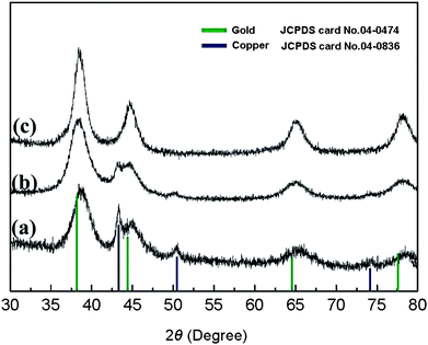 |
| | Fig. 6
XRD patterns of Cu–Au BNMNs dried at 80 °C for 1h (a), annealed at 300 °C for 30min (b) and 400 °C for 6h (c). The molar ratio of Cu to Au is 1 to 0.3 and the thermal treatment was carried out in the air. | |
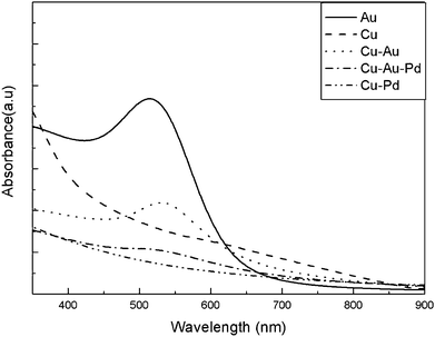
Optical properties
For comparison, blank experiments with pure Cu and 5.5nm Au were also done. Fig. 7 shows the UV-visible adsorption spectra of pure Au, pure Cu, Cu–Au, Cu–Pd and Cu–Au–Pd. Due to the predominant quantum size effects, the surface plasmon spectrum of Cu nanocrystals is strongly broadened and the surface plasmon peak of bulk Cu at 580nm is almost invisible.27 The surface plasmon absorption band of Cu–Au appears at 530nm. The intensity of the observed surface plasmon absorption band decreased, broadened and red-shifted comparing with the surface plasmon absorption band of pure Au nanocrystals. This red-shift phenomenon was also observed for Fe@Au core-shell bimetallic nanocrystals, which was attributed to bigger size and broader size distribution of Fe@Au core-shell bimetallic nanocrystals than pure Au nanocrystals.34 But in this paper, the size and size distribution of Cu–Au BNMNs and pure Au nanocrystals is almost identical, the only possible reason for the red-shift of Cu–Au BNMNs surface plasmon absorption band is the surface plasmon resonance enhanced absorption of Au in a core-shell structure. It was found that the surface plasmon absorption band of Cu–Au–Pd significantly damped that of Cu–Au and no other adsorption band appeared due to the Pd layer with a featureless absorption spectrum.
Ag-based BNMNs
Ag-based BNMNs with narrow size distribution was also synthesized by simply replacing cupric acetate with silver nitrate. The silver core is bigger (∼3.6 nm), so the sizes of Ag-based BNMNs are bigger than corresponding Cu-based BNMNs. 4.0 nm Ag–Pt, 4.2 nm Ag–Pd and 5.9 nm Ag–Au BNMNs with narrow size distribution are shown in Fig. 8a–c. ICP results indicate that unlike Cu-based BNMNs, the component ratios of Ag-based BNMNs are consistent with the ratios of initial precursors because no Ag was observed entering the water phase during the reaction (Table S1†). This may be related to the interaction of DODA with the surface of the metal nanoparticles. UV-Vis spectra of pure Ag, pure Au, Ag–Pt, Ag–Pd and Ag–Au were measured for comparison. The results are shown in Fig. 8d. Pure Au and Ag nanoparticles have surface plasmon absorption bands at 518 nm and 424 nm, respectively. As expected, Ag–Au nanoparticles show only one surface plasmon band at 488 nm in the range of 424 nm to 518 nm, which rules out the possibility of physical mixing of pure Ag and Au nanoparticles. For Ag–Pt and Ag–Pd nanocrystals, the surface plasmon band of Ag at 424 nm almost disappears due to the deposition of Pt or Pd.
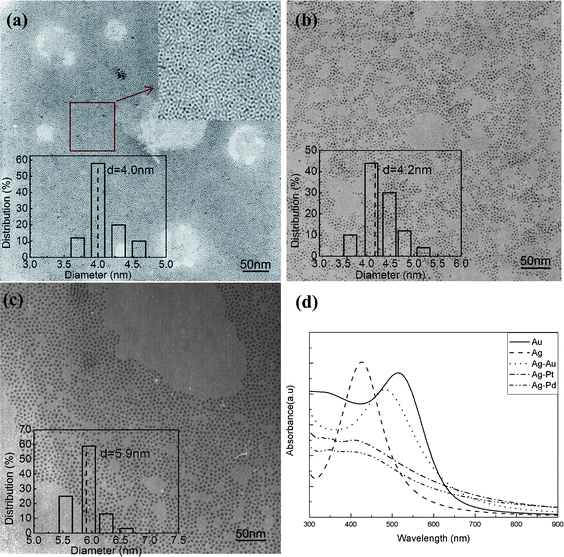 |
| | Fig. 8
TEM images of Ag-based BNMNs, (a) Ag–Pt, (b) Ag–Pd, (c) Ag–Au, (d) UV-visible spectra of pure Au, pure Ag, Ag–Au, Ag–Pt and Ag–Pd. The insets in (a–c) show size distribution histograms. The molar ratio of Ag to noble metal (Pt, Pd or Au) is 1 to 0.3. | |
Catalytic activity
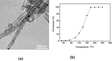
To prove that these BNMNs enhance the utilization of the noble metals, the CO oxidation activity of Cu–Pt, Ag–Pt and pure Pt nanocrystals supported on Mg3Si2O5(OH)4 nanotubes (Fig. S4, S5†) was studied. Mg3Si2O5(OH)4 nanotubes, chosen as supports due to their well-defined shape, large surface areas and high thermal stability, were prepared as reported previously.28 The noble metal catalysts including Cu–Pt BNMNs, Ag–Pt BNMNs and pure Pt nanocrystals were deposited on Mg3Si2O5(OH)4 nanotubes by a general method for oxide-supported metal nanoparticle catalysts reported by Stucky et al.,29 which is also suitable for Mg3Si2O5(OH)4 supports. The main advantage of this deposition method is that it will bring no apparent changes in size and size distribution of the nanocrystals, which was further confirmed by TEM characterization. As shown in Fig. 9a, Cu–Pt nanocrystals were homogeneously dispersed on the surface of Mg3Si2O5(OH)4 nanotubes with a loading capacity of 5 wt% (Pt loading capacity of 2.9 wt%) after calcination at 300 °C for 30 min. After the thermal treatment, the size of the nanocrystals supported on Mg3Si2O5(OH)4 nanotubes remained almost unchanged (Fig. 9a). The CO oxidation catalytic properties of Cu–Pt, Ag–Pt and pure Pt nanocrystals supported on Mg3Si2O5(OH)4 nanotubes were compared. Fig. 9b shows that the catalytic activity of Ag–Pt/Mg3Si2O5(OH)4 and pure Pt/Mg3Si2O5(OH)4 is similar, and the complete catalytic oxidation of CO occurred at about 140 °C. For Cu–Pt/Mg3Si2O5(OH)4 catalyst, the oxidation of CO occurred at a low temperature (40 °C) and the catalytic oxidation of CO completed at about 100 °C, which is a rather low conversion temperature. These results indicate that Cu–Pt nanocrystals have enhanced catalytic activity over pure Pt nanocrystals, i.e. Cu–Pt nanocrystals with low Pt loading capacity and CO conversion temperature favorable for the efficient utilization of Pt.
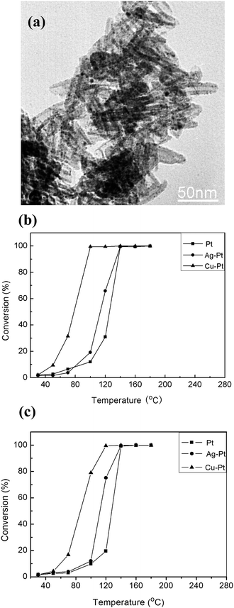 |
| | Fig. 9 (a) TEM images of Cu–Pt BNMNs (5 wt%) supported on Mg3Si2O5(OH)4 nanotubes (the images were taken from the sample after thermal treatment at 300 °C in the air for 30 min). Catalytic oxidation of CO using pure Pt, Ag–Pt BNMNs and Cu–Pt BNMNs supported on Mg3Si2O5 (OH) 4nanotubes (b), and CeO2 nanoparticles (c), respectively. The molar ratio of Cu (or Ag) to Pt is 1 to 0.3. | |
It is well known that metal–support interactions can alter the activities of supported noble metal catalysts.35–38 In order to exclude the possibility of enhanced activity of Cu–Pt BNMNs from (Cu–Pt)-Mg3Si2O5(OH)4 interactions, noble metal catalysts also supported on CeO2 nanoparticles. Fig. 9c shows the CO conversion as a function of temperature on CeO2 supported catalysts. The Cu–Pt/CeO2 catalyst still displays a high activity for CO oxidation (completed conversion at 120 °C), although the completed conversion temperature is a little higher than the Cu–Pt/Mg3Si2O5(OH)4 catalyst (complete conversion at 100 °C). The catalytic oxidation of CO on Ag–Pt/CeO2 and Pt/CeO2 still completed at about 140 °C similar to Ag–Pt/Mg3Si2O5(OH)4 and Pt/Mg3Si2O5(OH)4, respectively, this maybe due to the catalytic activity of CeO2 nanoparticles for CO oxidation at a higher temperature (>120 °C).30 The Cu–Pt BNMNs still had better activity for the low temperature oxidation of CO than pure Pt nanocrystals, which indicates that the enhanced activity of CO oxidation mainly resulted from Cu–Pt BNMNs with smaller size and narrower size distribution. All the catalytic data was repeated and during the experiments the catalysts show no apparent decrease in activity. Our study also shows that Mg3Si2O5(OH)4 nanotubes have equal or superior performance to CeO2 as catalyst supports for noble metals. The interaction between noble metals and Mg3Si2O5(OH)4 nanotubes is still under investigation.
In this study, when Cu–Pt BNMNs were annealed at 400 °C for 6 h, Cu–Pt BNMNs transformed into a CuPt alloy (Fig. 3c). After thermal treatment at high temperature, not only did the structure reconstruct but the size also increased (Fig. 10a). Fig. 10b indicates that the catalytic activity of this alloy supported on Mg3Si2O5(OH)4 nanotubes significantly decreased and the complete conversion of CO occurred at about 180 °C, which is much higher than for the Cu–Pt/Mg3Si2O5(OH)4 catalysts. It was reported recently that the light-off temperatures of CuPt alloy nanorods (20 nm × 2 nm) and CuPt spherical nanocrystals (2.5 nm) supported on γ-Al2O3 for catalytic oxidization of CO were 556 K and 490 K, respectively, which were significantly below the value of ∼700 K obtained for the commercial 2–3 nm Pt/Al2O3 catalyst.39 Here, the reduced catalytic activity of Cu–Pt BNMNS annealed at 400 °C may result from the increasing of particles size, but the restructuring from Cu–Pt to the CuPt alloy is most likely to be the main reason. The above results indicate that BNMNs with a Pt-rich shell are favorable for Pt catalytic activity for CO oxidation. For the Cu–Pt/Mg3Si2O5(OH)4 catalyst with very low Pt loading capacity, not only was the catalytic activity significantly improved, but also the amount of Pt was reduced, really achieving the efficient utilization of noble metal.
Conclusions
In summary, we have demonstrated a general and facile approach to prepare Cu- and Ag-based BNMNs with smaller size and narrow size distribution. The prepared BNMNs (with lower Pt loading capacity) exhibit excellent catalytic activity for CO oxidation compared with pure noble metal nanocrystals. Such bimetallic noble metal nanocrystals will be found many applications in other catalytic reactions and our approach is a prospective method for the efficient utilization of noble metals.
Acknowledgements
This work was supported by NSFC (20725102), the Fok Ying Tung Education Foundation (111012) and the State Key Project of Fundamental Research for Nanoscience and Nanotechnology (2011CB932402).
References
- P. K. Jain, X. H. Huang, I. H. El-Sayed and M. A. El-Sayed, Acc. Chem. Res., 2008, 41, 1578–1586 CrossRef CAS.
- B. Lim, M. J. Jiang, P. H. C. Camargo, E. C. Cho, J. Tao, X. M. Lu, Y. M. Zhu and Y. A. Xia, Science, 2009, 324, 1302–1305 CrossRef CAS; M. Q. Zhao and R. M. Crooks, Angew. Chem., Int. Ed., 1999, 38, 364–366 CrossRef CAS.
- Q. Yuan, J. Zhuang and X. Wang, Chem. Commun., 2009, 6613–6615 RSC; Q. Yuan, Z. Y. Zhou, J. Zhuang and X. Wang, Chem. Commun., 2010, 46(9), 1491–1493 RSC; Q. Yuan, Z. Y. Zhou, J. Zhuang and X. Wang, Chem. Mater., 2010, 22, 2395–2402 CrossRef CAS; Q. Yuan, Z. Y. Zhou, J. Zhuang and X. Wang, Inorg. Chem., 2010, 49, 5515–5521 CrossRef CAS.
- K. Aslan, P. Holley, L. Davies, J. R. Lakowicz and C. D. Geddes, J. Am. Chem. Soc., 2005, 127, 12115–12121 CrossRef CAS.
- F. P. Hu, P. K. Shen, Y. L. Li, J. Y. Liang, J. Wu, Q. L. Bao, C. M. Li and Z. D. Wei, Fuel Cells, 2008, 8, 429–435 CrossRef CAS.
- C. Wang, H. Daimon, Y. Lee, J. Kim and S. Sun, J. Am. Chem. Soc., 2007, 129, 6974–6975 CrossRef CAS.
- D. Zhao and B. Q. Xu, Angew. Chem., Int. Ed., 2006, 45, 4955–4959 CrossRef CAS.
- Y. M. Chen, F. Yang, Y. Dai, W. Q. Wang and S. L. Chen, J. Phys. Chem. C, 2008, 112, 1645–1649 CrossRef CAS.
- N. Pazos-Perez, Y. Gao, M. Hilgendorff, S. Irsen, J. Perez-Juste, M. Spasova, M. Farle, L. M. Liz-Marzan and M. Giersig, Chem. Mater., 2007, 19, 4415–4422 CrossRef CAS.
- N. S. Sobal, M. Hilgendorff, H. Mohwald, M. Giersig, M. Spasova, T. Radetic and M. Farle, Nano Lett., 2002, 2, 621–624 CrossRef CAS.
- R. Mu, Q. Fu, H. Liu, D. Tan, R. Zhai and X. Bao, Appl. Surf. Sci., 2009, 255, 7296–7301 CrossRef CAS.
- C. H. Yen, K. Shimizu, Y. Y. Lin, F. Bailey, I. F. Cheng and C. M. Wai, Energy Fuels, 2007, 21, 2268–2271 CrossRef CAS.
- N. Vila, M. Van Brussel, M. D'Amours, J. Marwan, C. Buess-Herman and D. Belanger, J. Electroanal. Chem., 2007, 609, 85–93 CrossRef CAS.
- S. Alayoglu, A. U. Nilekar, M. Mavrikakis and B. Eichhorn, Nat. Mater., 2008, 7, 333–338 CrossRef CAS.
- S. H. Zhou, B. Varughese, B. Eichhorn, G. Jackson and K. McIlwrath, Angew. Chem., Int. Ed., 2005, 44, 4539–4543 CrossRef CAS.
- C. Pan, F. Dassenoy, M. J. Casanove, K. Philippot, C. Amiens, P. Lecante, A. Mosset and B. Chaudret, J. Phys. Chem. B, 1999, 103, 10098–10101 CrossRef CAS.
- W. R. Lee, M. G. Kim, J. R. Choi, J. I. Park, S. J. Ko, S. J. Oh and J. Cheon, J. Am. Chem. Soc., 2005, 127, 16090–16097 CrossRef CAS.
- J. H. Hodak, A. Henglein and G. V. Hartland, J. Phys. Chem. B, 2000, 104, 5053–5055 CrossRef CAS.
- J. H. Hodak, A. Henglein and G. V. Hartland, J. Chem. Phys., 2001, 114, 2760–2765 CrossRef CAS.
- B. Rodriguez-Gonzalez, A. Burrows, M. Watanabe, C. J. Kiely and L. M. Liz-Marzan, J. Mater. Chem., 2005, 15, 1755–1759 RSC.
- T. J. Schmidt, M. Noeske, H. A. Gasteiger, R. J. Behm, P. Britz, W. Brijoux and H. Bonnemann, Langmuir, 1997, 13, 2591–2595 CrossRef CAS.
- T. Shibata, H. Tostmann, B. Bunker, A. Henglein, D. Meisel, S. Cheong and M. Boyanov, J. Synchrotron Radiat., 2001, 8, 545–547 CrossRef CAS.
- M. Arenz, K. J. J. Mayrhofer, V. Stamenkovic, B. B. Blizanac, T. Tomoyuki, P. N. Ross and N. M. Markovic, J. Am. Chem. Soc., 2005, 127, 6819–6829 CrossRef CAS.
- F. Maillard, M. Eikerling, O. V. Cherstiouk, S. Schreier, E. Savinova and U. Stimming, Faraday Discuss., 2004, 125, 357–377 RSC.
- V. Subramanian, E. E. Wolf and P. V. Kamat, J. Am. Chem. Soc., 2004, 126, 4943–4950 CrossRef CAS.
- M. Brust, M. Walker, D. Bethell, D. J. Schiffrin and R. Whyman, J. Chem. Soc., Chem. Commun., 1994, 801–802 RSC.
- S. L. Shen, J. Zhuang, X. X. Xu, A. Nisar, S. Hu and X. Wang, Inorg. Chem., 2009, 48, 5117–5128 CrossRef CAS; S. L. Shen, Z. H. Tang, Q. Liu and X. Wang, Inorg. Chem., 2010, 49, 7799–7807 CrossRef CAS.
- X. Wang, J. Zhuang, J. Chen, K. B. Zhou and Y. D. Li, Angew. Chem., Int. Ed., 2004, 43, 2017–2020 CrossRef CAS.
- N. F. Zheng and G. D. Stucky, J. Am. Chem. Soc., 2006, 128, 14278–14280 CrossRef CAS.
- K. B. Zhou, X. Wang, X. M. Sun, Q. Peng and Y. D. Li, J. Catal., 2005, 229, 206–212 CrossRef CAS.
- I. Lisiecki and M. P. Pileni, J. Am. Chem. Soc., 1993, 115, 3887–3896 CrossRef CAS.
- I. Lisiecki, F. Billoudet and M. P. Pileni, J. Phys. Chem., 1996, 100, 4160–4166 CrossRef CAS.
- J. J. Brege, C. E. Hamilton, C. A. Crouse and A. R. Barron, Nano Lett., 2009, 9, 2239–2242 CrossRef CAS.
- J. Lin, W. L. Zhou, A. Kumbhar, J. Wiemann, J. Y. Fang, E. E. Carpenter and C. J. O'Connor, J. Solid State Chem., 2001, 159, 26–31 CrossRef CAS.
- B. L. Mojet, J. T. Miller, D. E. Ramaker and D. C. Koningsberger, J. Catal., 1999, 186, 373–386 CrossRef CAS.
- M. Comotti, W. C. Li, B. Spliethoff and F. Schuth, J. Am. Chem. Soc., 2006, 128, 917–924 CrossRef CAS.
- S. Bernal, J.
J. Calvino, M. A. Cauqui, J. M. Gatica, C. Larese, J. A. P. Omil and J. M. Pintado, Catal. Today, 1999, 50, 175–206 CrossRef CAS.
- M. Comotti, W. C. Li, B. Spliethoff and F. Schuth, J. Am. Chem. Soc., 2006, 128, 917–924 CrossRef CAS.
- Q. S. Liu, Z. Yan, N. L. Henderson, J. C. Bauer, D. W. Goodman, J. D. Batteas and R. E. Schaak, J. Am. Chem. Soc., 2009, 131, 5720–5721 CrossRef CAS.
|
| This journal is © The Royal Society of Chemistry 2011 |
Click here to see how this site uses Cookies. View our privacy policy here.