DOI:
10.1039/C0NR00546K
(Review Article)
Nanoscale, 2011,
3, 59-70
Molecular strategies to read and write at the nanoscale with far-field optics
Received
28th July 2010
, Accepted 26th August 2010
First published on 11th October 2010
Abstract
Diffraction prevents the focusing of ultraviolet and visible radiations within nanoscaled volumes and, as a result, the imaging and patterning of nanostructures with conventional far-field illumination. Specifically, the irradiation of a fluorescent or photosensitive material with focused light results in the simultaneous excitation of multiple chromophores distributed over a large area, relative to the dimensions of single molecules. It follows that the spatial control of fluorescence and photochemical reactions with molecular precision is impossible with conventional illumination configurations. However, the photochemical and photophysical properties of organic chromophores can be engineered to overcome diffraction in combination with patterned or reiterative illumination. These ingenious strategies offer the opportunity to confine excited chromophores within nanoscaled volumes and, therefore, restrict fluorescence or photochemical reactions within subdiffraction areas. Indeed, information can be “read” in the form of fluorescence and “written” in the form of photochemical products with resolution down to the nanometre level on the basis of these innovative approaches. In fact, these promising far-field optical methods permit the convenient imaging of biological samples and fabrication of miniaturized objects with unprecedented resolution and can have long-term and profound implications in biomedical research and information technology.
 Janet Cusido | Janet Cusido received a BS in Chemistry from the University of Florida (USA) in 2005 and a MS in Chemistry from the same institution in 2007. Currently, she is enrolled in the chemistry graduate program at the University of Miami (USA). Her graduate research in the laboratories of Professor Raymo focuses on the design and synthesis of photoswitchable organic fluorophores for imaging applications. She is the author of six publications in the areas of chemical synthesis and photochemistry. |
 Stefania Impellizzeri | Stefania Impellizzeri received a Laurea in Chemistry from the University of Bologna (Italy) in 2006. Currently, she is enrolled in the chemistry graduate program at the University of Miami (USA). Her graduate research in the laboratories of Professor Raymo focuses on the design and synthesis of photoswitchable luminescent nanoparticles for imaging applications. She is the author of six publications in the areas of chemical synthesis, electrochemistry and photochemistry. |
 Françisco M. Raymo | Françisco M. Raymo received a Laurea in Chemistry from the University of Messina (Italy) in 1992 and a PhD in Chemistry from the University of Birmingham (UK) in 1996. He was a postdoctoral associate at the University of Birmingham (UK) in 1996–1997 and at the University of California, Los Angeles (USA) in 1997–1999. He was appointed Assistant Professor of Chemistry at the University of Miami (USA) in 2000 and promoted to Associate Professor in 2004 and Full Professor in 2009. His research interests combine the design, synthesis and analysis of functional molecule-based materials. Specifically, he is developing luminescent probes and photochromic switches for imaging applications. He is the author of more than 170 publications in the areas of chemical synthesis, computational chemistry, electrochemistry, materials science, photochemistry and supramolecular chemistry. |
1. Diffraction, focusing and resolution
Organic molecules absorb radiations across the ultraviolet and visible regions of the electromagnetic spectrum with concomitant transitions from ground to excited electronic states.1 Excited chromophores can then release the absorbed energy in the form of fluorescence or by undergoing chemical reactions. In turn, these photophysical and photochemical processes can be exploited to “read” and “write” information optically from fluorescent specimens and into photosensitive materials respectively. Indeed, fluorescence microscopy2 and optical lithography3 are extensively used to visualize (read) biological samples and pattern (write) inorganic substrates on the basis of the photophysical and photochemical properties of certain organic chromophores. However, diffraction4 prevents the focusing of ultraviolet and visible radiations into volumes of nanoscaled dimensions and, as a result, limits the resolution of these powerful techniques to the submicron domain.
The encounter of a propagating light wave with an object causes a spatial redistribution of the radiation intensity.4 The phenomenon is termed diffraction and can be explained by assuming that each point on the front of a propagating primary wave is the source of a secondary spherical wavelet. The superimposition of the many wavelets beyond the wavefront ensures propagation and defines the intensity of the propagating radiation. When light reaches the edge of an object, however, only the unobstructed points on the wavefront become wavelet sources. The interference of the resulting wavelets controls the intensity distribution of the light transmitted beyond the object.
Diffraction defines the intensity distribution of light on the focal plane of a lens and prevents the focusing of radiations into a single point.4 Indeed, the diffraction pattern (Airy pattern) of a point source of light (Fig. 1) on the focal plane of a lens consists of a circular spot (Airy disk) surrounded by concentric rings (Airy rings). Approximately 84% of the intensity of the focused light is in the Airy disk, while the rest is distributed in the Airy rings. The radius (r) of the Airy disk is related to the radiation wavelength (λ), the refractive index (n) of the medium interposed between the point source and the lens and the semiaperture angle (θ) of the lens, according to eqn (1). The very same parameters control also the thickness (z) of the Airy disk, according to eqn (2). In fact, constructive interference above and below the focal plane results in significant intensity distribution also along the optical axis. Thus, a conventional lens (θ ≈ 70°) operating in air (n ≈ 1) cannot focus radiations with λ longer than 200 nm into a disk with r and z smaller than 130 and 220 nm respectively. These dimensions are, at least, two orders of magnitude greater than those of most organic molecules. As a consequence, the illumination of a fluorescent specimen or a photosensitive material through a lens generally results in the simultaneous excitation of large collections of chromophores and cannot be used to confine fluorescence or a photochemical transformation respectively within a nanoscaled volume.
| |  | (1) |
| |  | (2) |
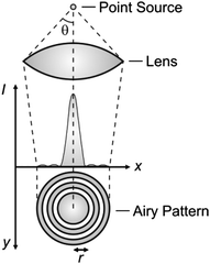 |
| | Fig. 1 The light propagating from a point source through a lens is diffracted on the focal plane in the form of an Airy pattern with a central disk of high intensity surrounded by concentric rings of low intensity. | |
The implications of diffraction on focusing dictate the resolving power of lens-based optics.4 In fact, the Airy patterns of two independent point sources of light can be distinguished (spatially resolved) on the focal plane of a lens only if their center-to-center distance is greater than r (Fig. 2a) or, at least, equal to it. Instead, a distance smaller than r results in the overlap of the Airy disks (Fig. 2b) with the formation of two unresolved diffraction patterns on the focal plane. Thus, the horizontal resolution of a lens-based instrument is ultimately dictated by the dependence of r on λ, according to eqn (1), and cannot be shrunk down to the nanometre level, if ultraviolet and visible radiations are employed in conjunction with conventional chromophores and illumination protocols.
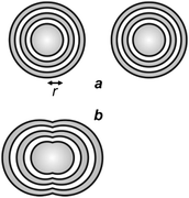 |
| | Fig. 2 Two Airy patterns are spatially resolved (a) if their center-to-center distance is greater than r, and spatially unresolved (b) if their center-to-center distance is smaller than r. | |
2. Near-field optics, far-field optics and chromophores
The restrictions associated with the lateral resolution of lens-based optics can be overcome by avoiding focusing altogether and relying instead on the evanescent nature of electromagnetic radiations at short distances from their source.5 Indeed, the behavior of the electric and magnetic fields of a radiation at distances shorter than λ (near-field region) from the source is significantly different from that at distances longer than 2λ (far-field region). In the near-field region, an electromagnetic radiation exiting an aperture of subdiffraction dimensions can be confined within a subdiffraction area. In fact, the scanning of a tip with a small aperture over a fluorescent or photosensitive sample can be exploited to read or write information respectively at the nanometre level. Nonetheless, the stringent distance constraints of the near-field region demand a subwavelength separation between aperture and sample. As a result, near-field illumination can only access exposed surfaces and cannot be extended to the interior of three-dimensional objects (e.g., cells).
Far-field illumination is essential to overcome the distance limitations of near-field optics. The diffraction of propagating waves in the far-field region, however, and its implications on the intensity distribution of focused light cannot be avoided. Fortunately, the photochemical and photophysical properties of organic chromophores can be engineered to circumvent diffraction and permit the reading and writing of information at the nanoscale with far-field optics.6–13 Indeed, the electronic transitions occurring in molecules with the absorption and emission of electromagnetic radiations permit the confinement of the spatial distribution of either fluorescent species or reactive intermediates within subdiffraction volumes. Similarly, chemical reactions occurring in the excited state of certain molecules can be exploited to resolve temporally chromophoric systems co-localized within the same subdiffraction volume. In fact, the subtle manipulation of the excited-state dynamics of chromophoric systems offers the opportunity to implement molecular strategies for nanoscaled reading and writing with focused light.
3. Subdiffraction confinement of excited chromophores
The focusing of light on a sample with a high density of chromophores results in the concomitant excitation of multiple molecules contained within the same Airy pattern. The many excited chromophores within a single focal spot can emit light or undergo chemical reactions on the same timescale and cannot be resolved spatially or temporally. Specifically, the excited-state population on the focal plane parallels the spatial distribution of the excitation intensity. In one dimension (x in Fig. 1), the intensity profile across the Airy pattern can be approximated to a Gaussian function with a width that increases with r.4 Thus, the spatial distribution of the excited chromophores on the focal plane is ultimately controlled by the dependence of r on λ, according to eqn (1).
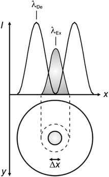
In order to narrow the relatively wide spatial distribution of excited chromophores imposed by diffraction, part of the excited molecules can be “forced” back to the ground state within the focal spot on the basis of stimulated emission.6 Indeed, a molecule can absorb an exciting photon of appropriate wavelength (λEx in Fig. 3) to undergo a transition from the ground state (S0) to one of the vibrational levels of the first singlet excited state (S1). After thermal relaxation to the lowest vibrational level of S1, the excited molecule can interact with a depleting photon of slightly longer wavelength (λDe) to decay into a high vibrational level of S0. Thus, the concomitant illumination of a collection of chromophores with focused light at λEx and patterned light at λDe can be exploited to engineer the spatial distribution of the excited chromophores. For example, the superimposition of the maximum of a Gaussian profile at λEx with one of the minima of a standing wave at λDe (Fig. 4) results in the depletion of the excited molecules at the periphery of the former and in the confinement of excited species at its center. Specifically, the full width (Δx) at half maximum of the excited-state distribution is controlled by the ratio between the depleting intensity (IDe) at the maximum of the standing wave and the saturation intensity (IS), according to eqn (3). In turn, IS is the intensity required to deactivate 50% of the excited molecules and is a constant characteristic of the chromophore. It follows that Δx shorter than 10 nm can be achieved with a conventional lens (θ ≈ 70°), operating in air (n ≈ 1) at λEx longer than 200 nm, only if IDe is, at least, one order of magnitude greater than IS.
| |  | (3) |
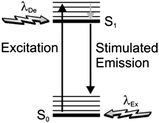 |
| | Fig. 3 Excitation of a molecule from the ground state (S0) to one of the vibrational levels of the first singlet excited state (S1), upon absorption of a photon at one wavelength (λEx), can be followed by thermal relaxation to the lowest vibrational level of S1 and then stimulated emission, upon interaction with a photon at another wavelength (λDe), with concomitant depletion of S1. | |
 |
| | Fig. 4 The superimposition of an Airy disk and doughnut-shaped pattern at the excitation (λEx) and depletion (λDe) wavelengths respectively of a chromophore confines the excited-state distribution within the doughnut hole. | |
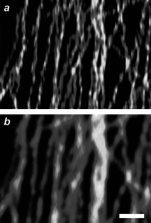
The stimulated-emission depletion (STED) of excited chromophores can be extended from one to two dimensions with the overlap of a doughnut-shaped pattern at λDe on an Airy disk at λEx (Fig. 4).6 This particular illumination protocol confines the excited species within the doughnut hole and permits the “reading” of fluorescence from areas of nanoscaled dimensions. In fact, scanning the overlapped circular spot and doughnut-shaped pattern over a fluorescent sample offers the opportunity to construct point-by-point fluorescence images with subdiffraction resolution. Furthermore, this nanoscopic methodology can be applied to essentially any fluorescent molecule, since any excited electronic state can, in principle at least, be depleted on the basis of stimulated emission. Indeed, early demonstrations14 of STED imaging with selected organic dyes (Pyridine 2 and RH414) have eventually been extended to a diversity of synthetic15 and genetically encoded16,17chromophores over the past decade. For example, a STED image (Fig. 5a) of living neurons, immunolabeled with the commercial dye Atto 647N, can resolve individual synaptic vesicles that cannot otherwise be distinguished with conventional illumination (Fig. 5b).15j This particular fluorophore can be excited at 647 nm (λEx) and depleted at 750 nm (λDe) with an IS of 10–20 MW cm−2. In particular, the STED image in Fig. 5 was recorded by illuminating the specimen with a pair of pulsed lasers, operating at λEx and λDe with intensities of 3.5–5 and 400 MW cm−2 respectively, and isolating the spontaneous emission from the stimulated one, as well as from the exciting and depleting radiations, with a combination of dichroic mirrors and bandpass filters. These experimental conditions ensure the confinement of fluorescence in a circular spot with a width of only 62 nm (Fig. 5c), while conventional illumination translates into a width of 261 nm (Fig. 5d). In fact, this ingenious protocol to overcome diffraction is becoming an invaluable analytical tool for the noninvasive visualization of cellular structures and processes in real time with a resolving power down to the nanometre level.15–17 Furthermore, it can also be adapted to produce spherical nanosized focal spots and achieved isotropic resolution in three dimensions down to the nanometre level.15i Nonetheless, the relatively high IS associated with the stimulated emission of fluorescent dyes demands hundreds of megawatts per square centimetre for IDe in order to confine excitation within nanoscaled areas, according to eqn (3). These harsh irradiation conditions can promote competitive photochemical pathways, encourage sample degradation and complicate the experimental implementation of this subdiffraction imaging strategy.15b,d
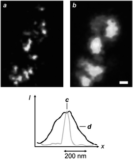 |
| | Fig. 5
STED (a) and confocal (b) images (scale bar = 250 nm) of neurons immunolabeled with Atto 647N and profiles of the emission intensities measured across the focal spots with STED (c) and confocal (d) illuminations (reproduced from ref. 15j with permission). | |
In principle, stimulated emission can also be exploited to confine photochemical transformations within subdiffraction volumes.18 Indeed, the illumination of a photosensitive material with a pair of offset beams at λEx and λDe results in a spatial distribution of excited chromophores and, eventually photochemical products, that is controlled by the overlap between the two focal spots. For example, the irradiation of malachite green carbinol base, embedded in an acrylic resin, with a laser pulse of 200 fs and 7 mW at 800 nm (λEx) results in the simultaneous absorption of two photons with a transition from S0 to S1 (Fig. 6). Excitation is then followed by intersystem crossing to the first triplet excited state (T1), which promotes the radical polymerization of acrylate monomers after electron transfer. However, the concomitant illumination of the sample with another laser pulse of 50 ps and 70 mW at 800 nm (λDe) stimulates emission and promotes the transition from S1 to S0, preventing intersystem crossing. It follows that the radical polymerization can be controlled spatially by regulating the position of the two focal spots at λEx and λDe. In fact, the lateral translation of the two spots across the photosensitive specimen results in the “writing” of polymer lines with subdiffraction width across the sample (Fig. 7a). Furthermore, the modulation of the depleting beam with a shutter wheel can be exploited to turn on and off depletion and generate periodic patterns along the scanning direction (Fig. 7b), demonstrating that depletion is indeed controlling the photochemical transformation. It is important to notice, however, that the depleting pulse must be delayed by few picoseconds, relative to the exciting one, to permit the vibrational relaxation of S1 before stimulated emission. Nonetheless, a delay of the depleting pulse of up to 13 ns did not translate into any significant change in the photochemical patterning. Thus, stimulated emission, after all, might not be the actual mechanism responsible for depletion in this particular system. Presumably, the participation of long-lived intermediates is responsible for preventing intersystem crossing.
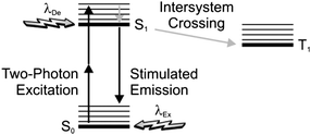 |
| | Fig. 6 After two-photon excitation of the ground state (S0), stimulated emission can be exploited to deplete the first singlet excited state (S1) and prevent intersystem crossing to the first triplet excited state (T1). | |
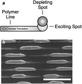 |
| | Fig. 7 (a) The translation of an acrylic resin, doped with malachite green carbinol base, under overlapped exciting and depleting focal spots results in the patterning of a polymer line with a width defined by the degree of overlap of the two spots. (b) A scanning electron micrograph (scale bar = 400 nm) of a sample patterned while turning on and off the depleting beam shows that the width of the written polymer lines changes with the modulation of the depleting spot (reproduced from ref. 18a with permission). | |
4. Subdiffraction confinement of chromophores in the ground state
Illumination protocols for the acquisition of STED images can be adapted to deplete the S0 of a chromophore, rather than its S1.6 In particular, exciting and depleting beams of identical wavelength (λEx = λDe) can be employed to ensure the population of S1 in the doughnut hole (Fig. 4) and intersystem crossing to T1 within the actual doughnut. Indeed, the intensity of the depleting beam can be increased sufficiently, relative to that of the exciting beam, to ensure a high probability of populating T1 only in the doughnut. However, the lifetime of S1 is significantly shorter than that of T1 for the vast majority of organic chromophores. As a result, molecules in the doughnut hole decay rapidly back to S0, while those within the actual doughnut remain in T1. It follows that S0 is confined within a subdiffraction area and depleted in the surrounding region during the lifetime of T1.
In the case of chromophores able to decay from S1 to S0 radiatively, ground-state depletion (GSD) permits the transient subdiffraction confinement of fluorescence.6 Furthermore, the IS associated with depletion, in this instance, can be up to six orders of magnitude smaller than that necessary for stimulated emission. In fact, GSD protocols offer the opportunity to lower dramatically the depletion intensities, relative to STED, required to achieve nanoscaled resolution. Indeed, subdiffraction images of a diversity of specimens have successfully been acquired with depletion intensities of only few kilowatts per square centimetre.15m,19 For example, a GSD image (Fig. 8a) of the microtubular network of a human embryonic kidney cell, immunolabeled with the commercial dye Atto 532, shows structural details that cannot be appreciated in a conventional confocal image (Fig. 8b). This GSD image was recorded by illuminating the specimen with a continuous-wave laser configured to generate a depleting beam at 532 nm with an intensity of 85 kW cm−2 and then an exciting beam at the same wavelength with an intensity of only 7 kW cm−2. Under these conditions, fluorescence is confined within a nanoscaled region and the scanning of the illuminating beams permits the image reconstruction. Nonetheless, the T1 of most chromophores is relatively reactive and, despite the relatively low irradiation intensities associated with GSD, significant photobleaching generally accompanies image acquisition.
 |
| | Fig. 8
GSD (a) and confocal (b) images (scale bar = 500 nm) of microtubules immunolabeled with Atto 532 (reproduced from ref. 19b with permission). | |
The subdiffraction confinement of chromophores in S0 can also be achieved by illuminating the specimen with a pattern of parallel lines.20,21 Specifically, a sinusoidal standing wave with high peak intensity can excite all chromophores from S0 to S1 anywhere in the illuminated area with the exception of the region around the wave minima. When the excited chromophores can then decay emissively back to S0, a wide field-image of the sample reveals parallel fluorescent lines separated by nonfluorescent gaps of subdiffraction width. The scanning of the exciting pattern orthogonally to the line direction and, eventually, the gradual rotation and translation of the pattern across the specimen can be exploited to probe the overall sample. The experimental implementation of this illumination protocol is somewhat simpler than those associated with STED and GSD. However, the subdiffraction confinement of a nonfluorescent state, in this instance, results in the generation of a “negative” image, which requires post-acquisition computation to be converted into a conventional “positive” image. In addition to extensive computation, this methodology for nanoscale reading can also suffer from significant photobleaching of the chromophores, because of the relatively high peak intensities required to saturate the S0 → S1 transition in the illuminated areas.
5. Subdiffraction confinement through opposing chemical reactions
The illumination scheme required for STED and GSD can be adapted to control the spatial distribution of the two interconvertible states of a photochromic compound.6 Indeed, photochromic molecules switch from one state to another (Fig. 9a and b) under irradiation at an appropriate wavelength (λ1), as a result of chemical transformations.22 The product of the photochemical reaction can then revert back to the original species thermally and/or upon illumination at a different wavelength (λ2). Thus, the irradiation of a collection of photochromic compounds with a circular spot at λ1 and an overlapped doughnut-shaped pattern at λ2 results in the confinement of only one of the two interconvertible states in the doughnut hole (Fig. 9c).
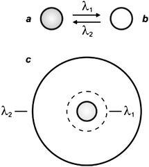 |
| | Fig. 9 Photochromic compounds switch reversibly between two states (a and b) under irradiation at appropriate wavelengths (λ1 and λ2). One of their two interconvertible states can be confined within a subdiffraction area (c) by focusing overlapped circular and doughnut-shaped spots at λ1 and λ2 respectively on the sample. | |
Generally, the two interconvertible states of a photochromic system differ significantly in their stereoelectronic properties and, as a result, in their ability to absorb ultraviolet and visible radiations.22 Furthermore, the structural and electronic changes associated with photochromic transformations can be exploited to switch the emission of complementary fluorophores under the influence of λ1 and λ2.23 In fact, the photochemical and photophysical properties of the resulting fluorophore–photochrome assemblies, in combination with patterned illumination (Fig. 9c), can be exploited to confine fluorescence in a subdiffraction area and record images with nanoscaled resolution.24 For example, the covalent connection of a diarylethene photochrome to a rhodamine fluorophore results in the assembly of the photoswitchable fluorescent dyad 1 (Fig. 10).24d The irradiation of this compound at 375 nm (λ1) closes the central ring of the diarylethene photochrome to form 2 (Fig. 10) and the illumination of the resulting species at 671 nm (λ2) regenerates the original isomer. The excitation of the rhodamine fluorophore at 543 nm, however, is accompanied by intense fluorescence only when the diarylethene photochrome is in the open form (1). Within the other isomer (2), energy transfer from the S1 of the fluorophore to the S0 of the photochrome quenches the emission of the former. Thus, the confinement of the emissive isomer 1 in the doughnut-hole (Fig. 9c) ensures the localization of fluorescence within a subdiffraction area. In fact, the covalent attachment of this fluorophore–photochrome dyad to silica nanoparticles, through its pendant amide bond, can eventually be exploited to image the resulting constructs with subdiffraction resolution. Indeed, the profile of the emission intensity acquired with patterned illumination offers the opportunity to resolve neighboring nanoparticles (Fig. 11a), which cannot otherwise be distinguished in conventional confocal mode (Fig. 11b). Specifically, the sample was illuminated with three independent lasers operating at 375, 671 and 543 nm to ensure the subdiffraction confinement of the emissive isomer 1 and the excitation of the rhodamine fluorophore. The main advantage offered by these switchable probes is that irradiation intensities significantly lower than those necessary for STED and GSD are sufficient to achieve nanoscaled resolution. Nonetheless, these molecules tolerate only a relatively small number of switching cycles, limiting the number of scans possible for image acquisition.
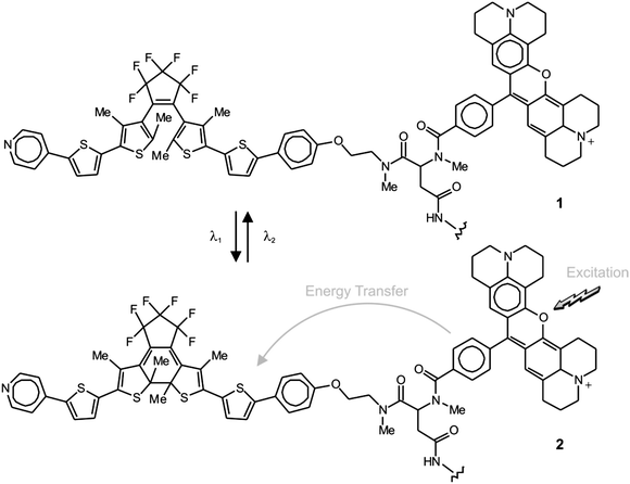 |
| | Fig. 10 Irradiation at 375 (λ1) and 671 nm (λ2) closes and opens respectively the central ring of the diarylethene component and switches reversibly the fluorophore–photochrome dyad between emissive (1) and nonemissive (2) states. | |
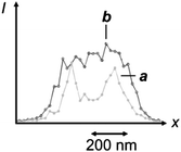 |
| | Fig. 11 Profile of the emission intensity of silica nanoparticles coated with 1 recorded by illuminating the sample with a circular spot at 375 nm, overlapped with a doughnut-shaped one at 671 nm and concomitant irradiation at 543 nm (a) or in conventional confocal mode (b) (reproduced from ref. 24d with permission). | |
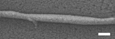
The photoinduced interconversion of the two states of a photochromic compound can also be exploited to generate a nanostructured pattern on a photoresist.25 In fact, the distinct absorption properties of the two states offer the opportunity to control the spatial distribution of the transmittance across a photochromic mask. Specifically, the illumination of a photochromic film with two offset standing waves at λ1 and λ2 (Fig. 12a) results in the spatial segregation of the two states. If the maxima of the wave at λ1 are positioned on the minima of that at λ2, then only one state (Fig. 9b) can be localized in the regions around the nodes of the second wave. If this particular species does not absorb significantly at λ1, then radiations at this wavelength can propagate through the photochromic material, once again, in the regions around the nodes of the second wave (Fig. 12a). Furthermore, the width of the transmitted beam can be regulated by adjusting the relative intensity of the two waves and, eventually, can be reduced down to the nanoscale, if the wave at λ2 is significantly more intense of that at λ1. Thus, the overlaying of a photochromic mask on a photoresist, in combination with these illumination conditions, permits the excitation of nanoscaled regions on the underlying substrate. For example, a poly(methyl methacrylate) film, doped with the diarylethene 3 (Fig. 13), was spin coated on an ultrathin poly(vinyl alcohol) layer deposited on a photoresist.25e The illumination of the resulting material with a pair of offset standing waves at 325 (λ1) and 633 (λ2) nm ensured the transmission of radiations at the short wavelength only at the nodes of the wave at the long one. In turn, the transmitted radiation reached the photoresist and imprinted a pattern of parallel lines with nanosized width and a separation corresponding to the period of the standing wave at λ2. Indeed, a scanning electron micrograph (Fig. 12b), recorded after developing the pattern on the resulting substrate, reveals lines with a width of 80 nm and a separation of 350 nm.
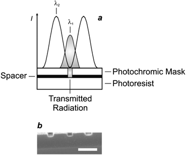 |
| | Fig. 12 (a) The illumination of a photoresist through a photochromic mask and an ultrathin spacer, consisting of a poly(methyl methacrylate) film doped with 3 and a poly(vinyl alcohol) layer respectively, with two standing waves at 325 (λ1) and 633 nm (λ2) results in the patterning of lines with nanoscaled width and separation. (b) The scanning electron micrograph (scale bar = 350 nm) recorded after developing the exposed substrate reveals lines with a width of 80 nm and a period of 350 nm (reproduced from ref. 25e with permission). | |
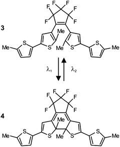 |
| | Fig. 13 Irradiation at 325 (λ1) and 633 nm (λ2) closes and opens respectively the central ring of these photochromic systems and switches it reversibly between two states (1 and 2). | |
The illumination protocol required for STED and GSD (Fig. 4) can be adapted to confine radical polymerizations within subdiffraction areas.26 Specifically, the beam at λEx can be designed to excite selectively a photoinitiator and promote the radical polymerization of an appropriate monomer. That at λDe can instead be exploited to excite a photoinhibitor able to trap radicals and prevent polymerization. Under these conditions, the monomer polymerization can only occur within the doughnut hole, offering the opportunity to pattern polymer lines of nanoscaled dimensions simply by translating the overlapped spots across the sample. These operating principles were implemented experimentally with formulations containing triethylene glycol dimethacrylate monomers, camphorquinone photoinitiators and tetraethylthiuram disulfide photoinhibitors. Illumination of the resulting mixture with a pair of lasers configured to generate a circular spot at 473 nm and a doughnut-shaped one at 364 nm resulted in the polymerization confinement within the doughnut hole. Furthermore, the intensity of the ultraviolet beam could be regulated, relative to that of the visible one, to shrink the polymerizing area to nanoscaled dimensions and the lateral scanning of both could be exploited to write nanostructured polymer lines. Consistently, the scanning electron micrograph (Fig. 14) of the patterned substrate reveals the “written” nanoscaled features resulting from the spatially controlled radical polymerization.
 |
| | Fig. 14
Scanning electron micrograph (scale bar = 200 nm) of a polymer line fabricated by illuminating a mixture of acrylate monomers, radical photoinitiators and radical photoinhibitors with the configuration in Fig. 4 (reproduced from ref. 26 with permission). | |
6. Temporal resolution of fluorophores co-localized in subdiffraction areas
The illumination of a collection of chromophores with focused light results in the concomitant excitation of multiple molecules residing within the same focal spot. If the excited chromophores decay radiatively back to S0, their collective emission can be recorded with far-field optics. However, the concomitant emission of multiple species co-localized within the same exciting spot prevents the spatial resolution of distinct fluorescence sources with a single far-field measurement. Nonetheless, sequential recordings can be exploited to distinguish adjacent fluorophores, if their photochemical and photophysical properties are engineered to permit their resolution in time. Specifically, this strategy requires a single fluorophore within a subdiffraction area to emit at a given time, while the others remain in a nonemissive state. Once localized, the emissive species must switch to a nonemissive state, while one of the other fluorophores must switch from a nonemissive to an emissive state. Under these conditions, reiterative fluorescence acquisition steps offer the opportunity to map the spatial coordinates of multiple emission sources within the same subdiffraction area and, eventually, reconstruct a complete image of the sample after appropriate data computation.
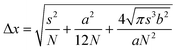
Early demonstrations of these clever operating principles were based on the ability of certain genetically encoded proteins to switch from a nonemissive to an emissive state under illumination at an appropriate wavelength.27–32 Later, this protocol, termed photoactivation localization microscopy (PALM), was extended to synthetic dyes designed to switch from nonfluorescent to fluorescent states.29f,33–35 For example, compound 5 (Fig. 15) is not fluorescent in its native form.33a,c Upon irradiation at an activation wavelength (λAc) of 375 nm, however, the [C–N] bond at the spirocenter cleaves to generate the fluorescent isomer 6 (Fig. 15). Specifically, the illumination of 6 at an excitation wavelength (λEx) of 532 nm is accompanied by intense fluorescence in the visible region. Thus, a specimen of interest (e.g., a cell) can be labeled with the nonemissive isomer 5 through amide-bond formation at its pendant carbonyl group. Illumination at λAc (a → b in Fig. 16) with low intensity switches a subfraction of probes to their fluorescent isomer. The low activation intensity is necessary to ensure a sparse population of fluorescent species at a given time, in order to maintain them at a distance greater than the diffraction barrier. The activated probes can then be excited at λEx (b → c in Fig. 16) a sufficient number of times to permit the collection of enough emitted photons for the localization of each fluorescent probe with nanoscaled precision. The coordinates of the localized species can then be stored and the active probes can be bleached (c → d in Fig. 16). The entire sequence of events can be reiterated multiple times until a sufficient number of coordinates becomes available for the reconstruction of a complete image of the sample. According to this method, the lateral resolution (Δx) of the reconstructed image is governed by eqn (4),36 where pixel size (a), the standard deviation (s) of the point-spread function, the number (N) of collected photons per probe and the background noise (b) dictate the magnitude of Δx. Thus, large N and small b values are required to confine Δx in the nanoscale. It follows that the active state of the switchable probes must be as bright as possible and the ratio between the emission intensities of the active and inactive states must be as high as possible. In fact, switchable molecules with large brightness and contrast ratios are essential for this nanoscopic technique.
| |  | (4) |
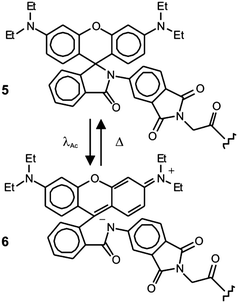 |
| | Fig. 15 The activation of the nonfluorescent species 5 at 375 nm (λAc) opens the five-membered ring at its core to generate the fluorescent isomer 6. | |
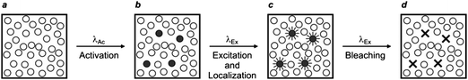 |
| | Fig. 16
PALM relies on the illumination of a labeled sample (a) at one wavelength (λAc) with a beam of low intensity to switch a small fraction of probes from a nonemissive to a fluorescent state (b). The activated fluorophores are excited at another wavelength (λEx), individually localized (c) and bleached (d). This sequence of steps is repeated multiple times until the coordinates of a sufficiently large number of probes are registered to compile a complete image of the sample. | |
A similar strategy for the reconstruction of images with nanoscaled resolution, called stochastic optical reconstruction microscopy (STORM), can be adopted with molecules able to switch from a fluorescent to a nonfluorescent state upon illumination at a deactivating wavelength (λDe).37,38 In particular, the cyanine dyes Cy5, Cy5.5 and Cy7 switch from emissive to nonemissive states upon illumination with a red laser (λDe),37 presumably as a result of the photoinduced addition of primary thiols, present in biological media, to the polymethine bridge of these dyes.39 This photochemical transformation is reversible and irradiation of the adduct with a green laser (λAc) restores the state and activates fluorescence. In fact, these compounds can be switched back and forth between emissive and nonemissive states for multiple cycles by alternating red and green irradiation. Thus, a sample labeled with one of these dyes can initially be illuminated at λDe with a relatively high intensity to switch essentially all molecules to their nonfluorescent state (a → b in Fig. 17). Subsequent irradiation at λAc with relatively low intensity can switch a subfraction of probes back to the emissive state (b → c in Fig. 17). The low intensity is necessary to ensure the activation of only a sparse number of probes in order to maintain them at distances longer than the diffraction barrier. The activated probes can be excited again at λDe with low intensity (c → d in Fig. 17). Under these conditions, they emit light in the form of fluorescence until they switch back to the nonfluorescent state. As a result, they can be localized with nanoscaled precision and their coordinates can be stored. This sequence of steps can be reiterated multiple times until a sufficient number of coordinates is available for the reconstruction of a complete image of the sample.
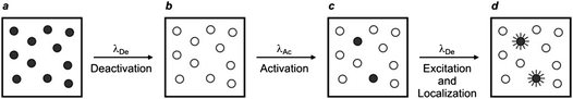 |
| | Fig. 17
STORM relies on the illumination of a labeled sample (a) at a deactivating wavelength (λDe) with a beam of high intensity to switch all probes from an emissive to a nonemissive state (b). The deactivated fluorophores are irradiated at an activating wavelength (λAc) with a beam of low intensity to switch a small fraction of probes back to the fluorescent state (c). The illumination of the sample again at λDe with a beam of low intensity excites the activated probes, which then emit light until they switch back to the nonemissive state. The emitted photons can be collected to localize individually the active probes (d). The activation and excitation steps can then be reiterated multiple times until the coordinates of a sufficiently large number of probes are registered to compile a complete image of the sample. | |
The reiterative nature of PALM and STORM translates into long times for image acquisition, relative to those required for STED and GSD strategies. However, the experimental implementation of the former methods is significantly simpler than that of the latter, which demands the alignment and simultaneous scanning with nanometre precision of up to three lasers. Nonetheless, PALM and STORM still require substantial modifications to commercial microscopes, mostly because of the need of activation or deactivation steps, in conjunction with actual fluorophore excitation. Specifically, at least a pair of lasers operating at λAc and λEx for PALM (Fig. 16) and at λDe and λAc for STORM (Fig. 17) are necessary. A significant simplification to the illumination configuration of these strategies is possible with certain organic fluorophores40–43 and inorganic nanoparticles44,45 able to emit, but also switch to a nonemissive state, when excited at a single wavelength. In particular, these systems display luminescence intermittence upon excitation, as a result of chemical and/or physical processes occurring in the excited state, but generally require relatively high excitation intensities and auxiliary reagents. Indeed, the high irradiation intensities ensure the effective population of T1 upon excitation and the presence of electron acceptors or donors promotes the oxidation or reduction respectively of the excited chromophore with the reversible formation of a relatively long-lived and nonfluorescent product. For example, the commercial dye Alexa 647 can be excited from S0 to S1 by illuminating the sample at 647 nm.41a The excited molecules can either emit light and revert to S0 or intersystem cross to T1. In the absence of molecular oxygen and in the presence of ascorbic acid, a compound in T1 can accept an electron to form a nonfluorescent radical anion. This species lives for about 50 ms, before regenerating the original molecule in S0. At an appropriate illumination intensity and ascorbic-acid concentration, most of the dyes can be maintained in the nonfluorescent state for tens of milliseconds, offering the opportunity to localize individually the few molecules left in the emissive state. The stochastic evolution of the excited-state population, however, results in fluorescence switching at different spatial coordinates. Thus, the sequential acquisition of snapshots permits the gradual localization of a sufficient number of dyes to compile, eventually, a complete image of the sample. Indeed, a reconstructed image (Fig. 18a) of microtubules in fixed 3T3 fibroblast, immunolabeled with Alexa 647 and recorded after the enzymatic removal of oxygen and the addition of ascorbic acid, reveals fine structural details that cannot be appreciated in the equivalent image recorded with conventional wide-field illumination (Fig. 18b). This clever protocol eliminates the need of an activating/deactivating irradiation source in addition to the exciting one. However, it requires the presence of appropriate reagents capable of exchanging electrons with dyes in T1 as well as the careful regulation of the experimental conditions to optimize the lifetime of the nonfluorescent state and permit localization of individual fluorophores with nanoscaled precision.
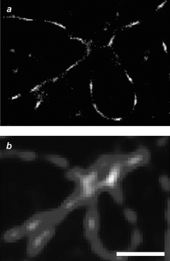 |
| | Fig. 18 Image (scale bar = 1 µm) of microtubules immunolabeled with Alexa 647 reconstructed after reiterative irradiation in the presence of ascorbic acid (a) or recorded with conventional wide-field illumination (b) (reproduced from ref. 41a with permission). | |
7. Conclusions
The relatively large dimensions imposed on focused light by diffraction prevent the reading and writing of information at the nanoscale with conventional far-field illumination. The photochemical and photophysical properties of organic chromophores, however, can be engineered to overcome diffraction, in combination with patterned or reiterative illumination schemes. Specifically, the patterned illumination of a collection of chromophores can be exploited to segregate spatially molecules in distinct electronic or isomeric states on the basis of stimulated emission, intersystem crossing or opposing photochemical reactions. These protocols permit the localization of fluorescence or the generation of photochemical products within nanoscaled volumes and, therefore, offer the opportunity for imaging or patterning respectively at the nanoscale. Alternatively, molecules at subdiffraction separations can be resolved temporally and localized individually in reiterative sequences of excitation and detection steps, if their fluorescence is designed to switch on and off in response to illumination. These methods permit the reconstruction of images with nanoscaled resolution with relatively simple experimental setups and data computations. Indeed, the emergence of valuable strategies for nanoscopic visualization with far-field optics is already providing invaluable information on the subtle factors regulating cellular processes and functions at the molecular level. Similarly, the ability to nanofabricate features with focused light offers the opportunity to produce ultraminiaturized objects with relatively inexpensive experimental setups. Thus, the advent of molecular strategies to overcome diffraction will ultimately have profound implications in biomedical research and information technology, in addition to contributing to the further understanding of the photochemistry and photophysics of organic compounds.
Acknowledgements
We thank the National Science Foundation (CAREER Award CHE-0237578 and CHE-0749840) and the University of Miami for financial support.
References
-
N. J. Turro, V. Ramamurthy and J. C. Scaiano, Principles of Molecular Photochemistry: an Introduction, University Science Book, Herndon, 2009 Search PubMed.
-
D. B. Murphy, Fundamentals of Light Microscopy and Electronic Imaging, Wiley-Liss, New York, 2001 Search PubMed.
-
B. J. Lin, Optical Lithography: Here is Why, SPIE, Bellingham, 2010 Search PubMed.
-
M. Born and E. Wolf, Principles of Optics, Cambridge University Press, Cambridge, 2002 Search PubMed.
-
A. V. Zayats and D. Richards, Nano-Optics and Near-Field Optical Microscopy, Artech House, Boston, 2009 Search PubMed.
-
(a) S. W. Hell, Nat. Biotechnol., 2003, 21, 1347 CrossRef CAS;
(b) S. W. Hell, M. Dyba and S. Jakobs, Curr. Opin. Neurobiol., 2004, 14, 599 CrossRef CAS;
(c) S. W. Hell, Phys. Lett. A, 2004, 326, 140 CrossRef CAS;
(d) S. W. Hell and L. Kastrup, Nachr. Chem., 2007, 55, 47 Search PubMed;
(e) S. W. Hell, Science, 2007, 316, 1153 CrossRef CAS;
(f) S. W. Hell, Nat. Methods, 2009, 6, 24 CrossRef CAS;
(g) S. W. Hell, R. Schmidt and A. Egner, Nat. Photonics, 2009, 3, 381 CrossRef CAS.
-
(a) M. Bates, B. Huang and X. Zhuang, Curr. Opin. Chem. Biol., 2008, 12, 505 CrossRef CAS;
(b) B. Huang, M. Bates and X. Zhuang, Annu. Rev. Biochem., 2009, 78, 993 CrossRef CAS;
(c) X. Zhuang, Nat. Photonics, 2009, 3, 365 CrossRef CAS.
- N. Ji, H. Shroff, H. Zhong and E. Betzig, Curr. Opin. Neurobiol., 2008, 18, 605 CrossRef CAS.
- M. G. L. Gustafsson, Nat. Methods, 2008, 5, 385 CrossRef CAS.
- M. Fernández-Suárez and A. Y. Ting, Nat. Rev. Mol. Cell Biol., 2008, 9, 929 CrossRef CAS.
- M. Heilemann, P. Dedecker, J. Hofkens and M. Sauer, Laser Photonics Rev., 2009, 3, 180 Search PubMed.
-
(a) J. Lippincott-Schwartz and S. Manley, Nat. Methods, 2009, 6, 21 CrossRef CAS;
(b) J. Lippincott-Schwartz and G. H. Patterson, Trends Cell Biol., 2009, 19, 555 CrossRef CAS.
- S. T. Hess, Nat. Methods, 2009, 6, 124 CrossRef CAS.
-
(a) S. W. Hell and J. Wichmann, Opt. Lett., 1994, 19, 780 Search PubMed;
(b) M. Schrader, F. Meinecke, K. Bahlmann, M. Kroug, C. Cremer, E. Soini and S. W. Hell, Bioimaging, 1995, 3, 147 CrossRef CAS;
(c) T. A. Klar and S. W. Hell, Opt. Lett., 1999, 24, 954 Search PubMed;
(d) T. A. Klar, S. Jakobs, M. Dyba, A. Egner and S. W. Hell, Proc. Natl. Acad. Sci. U. S. A., 2000, 100, 8206 CrossRef.
-
(a) K. I. Willig, S. O. Rizzoli, V. Westphal, R. Jahn and S. W. Hell, Nature, 2006, 440, 935 CrossRef CAS;
(b) G. Donnert, J. Keller, R. Medda, M. A. Andrei, S. O. Rizzoli, R. Lührmann, R. Jahn, C. Eggeling and S. W. Hell, Proc. Natl. Acad. Sci. U. S. A., 2006, 103, 11440 CrossRef CAS;
(c) R. J. Kittel, C. Wichmann, T. M. Rasse, W. Fouquet, M. Schmidt, A. Schmid, D. A. Wagh, C. Pawlu, R. R. Kellner, K. I. Willig, S. W. Hell, E. Buchner, M. Heckmann and S. J. Sigrist, Science, 2006, 312, 1051 CrossRef CAS;
(d) G. Donnert, C. Eggeling and S. W. Hell, Nat. Methods, 2007, 4, 81 CrossRef CAS;
(e) K. I. Willig, B. Harke, R. Medda and S. W. Hell, Nat. Methods, 2007, 4, 915 CrossRef CAS;
(f) W. Lin, R. Margolskee, G. Donnert, S. W. Hell and D. Restrepo, Proc. Natl. Acad. Sci. U. S. A., 2007, 104, 2471 CrossRef CAS;
(g) J. Sieber, K. I. Willig, C. Kutzner, C. Gerding-Reimers, B. Harke, G. Donnert, B. Rammner, C. Eggeling, S. W. Hell, H. Grubmüller and T. Lang, Science, 2007, 317, 1072 CrossRef CAS;
(h) V. P. Boyarskiy, V. N. Belov, R. Medda, B. Hein, M. Bossi and S. W. Hell, Chem.–Eur. J., 2008, 14, 1784 CrossRef CAS;
(i) R. Schmidt, C. A. Wurm, S. Jakobs, J. Engelhardt, A. Egner and S. W. Hell, Nat. Methods, 2008, 5, 539 CrossRef CAS;
(j) V. Westphal, S. O. Rizzoli, M. A. Lauterbach, D. Kamin, R. Jahn and S. W. Hell, Science, 2008, 320, 246 CrossRef CAS;
(k) A. C. Meyer, T. Frank, D. Khimich, G. Hoch, D. Riedel, N. M. Chapochnikov, Y. M. Yarin, B. Harke, S. W. Hell, A. Enger and T. Mose, Nat. Neurosci., 2009, 12, 444 CrossRef CAS;
(l) C. Eggeling, C. Ringemann, R. Medda, G. Scwarzmann, K. Sandhoff, S. Polyakova, V. N. Belov, B. Hein, C. von Middendorff, A. Schönle and S. W. Hell, Nature, 2009, 457, 1159 CrossRef;
(m) K. Kolmakov, V. N. Belov, J. Bierwagen, C. Ringemann, V. Müller, C. Eggeling and S. W. Hell, Chem.–Eur. J., 2010, 16, 158 CrossRef CAS;
(n) G. Y. Mitronova, V. N. Belov, M. Bossi, C. A. Wurm, L. Meyer, R. Medda, G. Moneron, S. Bretschneider, C. Eggeling, S. Jakobs and S. W. Hell, Chem.–Eur. J., 2010, 16, 4477 CrossRef CAS;
(o) J. Hotta, E. Fron, P. Dedecker, K. P. F. Janssen, C. Li, K. Müllen, B. Harke, J. Bückers, S. W. Hell and J. Hofkens, J. Am. Chem. Soc., 2010, 132, 5021 CrossRef CAS;
(p) S. J. Sahl, M. Leutenegger, M. Hilbert, S. W. Hell and C. Eggeling, Proc. Natl. Acad. Sci. U. S. A., 2010, 107, 6829 CrossRef CAS.
-
(a) K. I. Willig, R. R. Kellner, R. Medda, N. Hein, S. Jakobs and S. W. Hell, Nat. Methods, 2006, 3, 721 CrossRef CAS;
(b) B. Hein, K. I. Willig and S. W. Hell, Proc. Natl. Acad. Sci. U. S. A., 2008, 105, 14271 CrossRef CAS;
(c) U. V. Nagerl, K. I. Willig, B. Hein, S. W. Hell and T. Nonhoeffer, Proc. Natl. Acad. Sci. U. S. A., 2008, 105, 18982 CrossRef CAS;
(d) G. Moneron, R. Medda, B. Hein, A. Giske, V. Westphal and S. W. Hell, Opt. Express, 2010, 18, 1302 CrossRef CAS.
- C. Rickman, C. N. Medine, A. R. Dun, D. J. Moulton, O. Mandula, N. D. Halemani, S. O. Rizzoli, L. H. Chamberlain and R. R. Duncan, J. Biol. Chem., 2010, 285, 13535 CrossRef CAS.
-
(a) L. Li, R. R. Gattass, E. Gershgoren, H. Hwang and J. T. Fourkas, Science, 2009, 324, 910 CrossRef CAS;
(b) J. T. Fourkas, J. Phys. Chem. Lett., 2010, 1, 1221 Search PubMed.
-
(a) S. W. Hell and M. Kroug, Appl. Phys. B: Lasers Opt., 1995, 60, 495 CrossRef;
(b) S. Bretschneider, C. Eggeling and S. W. Hell, Phys. Rev. Lett., 2007, 98, 218103 CrossRef;
(c) J. Fölling, M. Bossi, H. Bock, R. Medda, C. A. Wurm, B. Hein, S. Jakobs, C. Eggeling and S. W. Hell, Nat. Methods, 2008, 5, 943 CrossRef.
-
(a) M. G. L. Gustafsson, Curr. Opin. Struct. Biol., 1999, 9, 627 CrossRef CAS;
(b) M. G. L. Gustafsson, J. Microsc., 2000, 198, 82 CrossRef CAS;
(c) M. G. L. Gustafsson, D. A. Agard and J. W. Sedat, Proc. SPIE-Int. Soc. Opt. Eng., 2000, 3919, 141;
(d) M. G. L. Gustafsson, Proc. Natl. Acad. Sci. U. S. A., 2005, 102, 13081 CrossRef CAS;
(e) M. G. L. Gustafsson, L. Shao, P. M. Carlton, C. J. R. Wang, I. N. Golubovskaya, W. Z. Cande, D. A. Agard and J. W. Sedat, Biophys. J., 2008, 94, 4957 CrossRef CAS;
(f) L. Shao, B. Isaac, S. Uzawa, D. A. Agard, J. W. Sedat and M. G. L. Gustafsson, Biophys. J., 2008, 94, 4971 CrossRef CAS;
(g) L. Schermelleh, P. M. Carlton, S. Haase, L. Shao, L. Winoto, P. Kner, B. Burke, M. C. Cardoso, D. A. Agard, M. G. L. Gustafsson, H. Leonhardt and J. W. Sedat, Science, 2008, 320, 1332 CrossRef CAS;
(h) P. Kner, B. B. Chhun, E. R. Griffis, L. Winoto and M. G. L. Gustafsson, Nat. Methods, 2009, 6, 339 CrossRef CAS;
(i) R. Heintzmann and M. G. L. Gustafsson, Nat. Photonics, 2009, 3, 362 CrossRef CAS.
-
(a) R. Heintzmann and C. Cremer, Proc. SPIE-Int. Soc. Opt. Eng., 1999, 3568, 185;
(b) R. Heintzmann, T. M. Jovin and C. Cremer, J. Opt. Soc. Am. A, 2002, 19, 1599 CrossRef.
-
Organic Photochromic and Thermochromic Compounds, ed. J. C. Crano and R. Guglielmetti, Plenum Press, New York, 1999 Search PubMed.
-
(a) F. M. Raymo and M. Tomasulo, Chem. Soc. Rev., 2005, 34, 327 RSC;
(b) F. M. Raymo and M. Tomasulo, J. Phys. Chem. A, 2005, 109, 7343 CrossRef CAS;
(c) J. Cusido, E. Deniz and F. M. Raymo, Eur. J. Org. Chem., 2009, 2031 CrossRef;
(d) I. Yildiz, E. Deniz and F. M. Raymo, Chem. Soc. Rev., 2009, 38, 1859 RSC.
-
(a) M. Hofmann, C. Eggeling, S. Jakobs and S. W. Hell, Proc. Natl. Acad. Sci. U. S. A., 2005, 102, 17565 CrossRef CAS;
(b) M. A. Schwentker, H. Bock, M. Hofmann, S. Jakobs, J. Bewersdorf, C. Eggeling and S. W. Hell, Microsc. Res. Tech., 2007, 70, 269 CrossRef CAS;
(c) M. Bossi, J. Fölling, M. Dyba, V. Westphal and S. W. Hell, New J. Phys., 2006, 8, 275 CrossRef;
(d) J. Fölling, S. Polyakova, V. Belov, A. van Blaaderen, M. L. Bossi and S. W. Hell, Small, 2008, 4, 134 CrossRef.
-
(a) R. Menon and H. I. Smith, J. Opt. Soc. Am. A, 2006, 23, 2290 CrossRef;
(b) H. Y. Tsai, G. M. Wallraff and R. Menon, Appl. Phys. Lett., 2007, 91, 094103 CrossRef;
(c) R. Menon, H. Y. Tsai and S. W. Thomas, Phys. Rev. Lett., 2007, 98, 043905 CrossRef;
(d) H. Y. Tsai, H. I. Smith and R. Menon, Opt. Lett., 2008, 33, 2916 Search PubMed;
(e) T. L. Andrew, H. Y. Tsai and R. A. Menon, Science, 2009, 324, 917 CrossRef CAS.
- T. F. Scott, B. A. Kowalski, A. C. Sullivan, C. N. Bowman and R. R. McLeod, Science, 2009, 324, 913 CrossRef CAS.
-
(a) S. T. Hess, T. P. K. Girirajan and M. D. Mason, Biophys. J., 2006, 91, 4258 CrossRef CAS;
(b) S. T. Hess, T. J. Gould, M. V. Gudheti, S. A. Maas, K. D. Mills and J. Zimmerberg, Proc. Natl. Acad. Sci. U. S. A., 2007, 104, 17370 CrossRef CAS;
(c) T. J. Gould, M. S. Gunewardene, M. V. Gudheti, V. V. Verkhusha, S.-R. Yin, J. A. Goose and S. T. Hess, Nat. Methods, 2008, 5, 1027 CrossRef CAS;
(d) T. J. Gould, V. V. Verkhusha and S. T. Hess, Nat. Protoc., 2009, 4, 291 Search PubMed.
-
(a) E. Betzig, G. H. Patterson, R. Sougrat, O. W. Lindwasser, S. Olenych, J. S. Bonifacino, M. W. Davidson, J. Lippincott-Schwartz and H. F. Hess, Science, 2006, 313, 1642 CAS;
(b) H. Shroff, C. G. Galbraith, J. A. Galbraith, H. White, J. Gillette, S. Olenych, M. W. Davidson and E. Betzig, Proc. Natl. Acad. Sci. U. S. A., 2007, 104, 20308 CrossRef CAS;
(c) S. Manley, J. M. Gillette, G. H. Patterson, H. Shroff, H. F. Hess, E. Betzig and J. Lippincott-Schwartz, Nat. Methods, 2008, 5, 155 CrossRef CAS;
(d) H. Shroff, C. G. Galbraith, J. A. Galbraith and E. Betzig, Nat. Methods, 2008, 5, 417 CrossRef CAS;
(e) D. Greenfield, A. L. McEvoy, H. Shroff, G. E. Crooks, N. S. Wingreen, E. Betzig and J. Liphardt, PLoS Biol., 2009, 7, e1000137 CrossRef.
-
(a) C. Geisler, A. Schönle, C. von Middendorf, H. Bock, C. Eggeling, A. Egner and S. W. Hell, Appl. Phys. A: Mater. Sci. Process., 2007, 88, 223 CrossRef CAS;
(b) H. Bock, C. Geisler, C. von Middendorf, S. Jakobs, A. Schönle, A. Egner, S. W. Hell and C. Eggeling, Appl. Phys. B: Lasers Opt., 2007, 88, 161 CrossRef CAS;
(c) A. Egner, C. Geisler, C. von Middendorff, H. Bock, D. Wenzel, R. Medda, M. Andresen, A. C. Stiel, S. Jakobs, C. Eggeling, A. Schönle and S. W. Hell, Biophys. J., 2007, 93, 3285 CrossRef CAS;
(d) A. C. Stiel, M. Andresen, H. Bock, M. Hilbert, J. Schilde, A. Schönle, C. Eggeling, A. Egner, S. W. Hell and S. Jakobs, Biophys. J., 2008, 95, 2989 CrossRef CAS;
(e) M. Andresen, A. C. Stiel, J. Fölling, D. Wenzel, A. Schönle, A. Egner, C. Eggeling, S. W. Hell and S. Jakobs, Nat. Biotechnol., 2008, 26, 1035 CrossRef CAS;
(f) I. Testa, A. Schönle, C. von Middendorff, C. Geisler, R. Medda, C. A. Wurm, A. C. Stiel, S. Jakobs, M. Bossi, C. Eggeling, S. W. Hell and E. Egner, Opt. Express, 2008, 16, 21093 CrossRef CAS.
-
(a) C. Flors, J. Hotta, H. Uji-i, P. Dedecker, R. Ando, H. Mizuno, A. Miyawaki and J. Hofkens, J. Am. Chem. Soc., 2007, 129, 13970 CrossRef CAS;
(b) P. Dedecker, J. Hotta, C. Flors, M. Silwa, H. Uji-i, M. B. J. Roeffaers, R. Ando, H. Mizuno, A. Miyawaki and J. Hofkens, J. Am. Chem. Soc., 2007, 129, 16132 CrossRef CAS;
(c) H. Mizuno, P. Dedecker, R. Ando, T. Fukano, J. Hofkens and A. Miyawaki, Photochem. Photobiol. Sci., 2010, 9, 239 RSC.
- J. S. Biteen, M. A. Thompson, N. K. Tselentis, G. R. Bowman, L. Shapiro and W. E. Moerner, Nat. Methods, 2008, 5, 947 CrossRef CAS.
-
(a) F. V. Subach, G. H. Patterson, S. Manley, J. M. Gillette, J. Lippincott-Schwartz and V. V. Verkhusha, Nat. Methods, 2009, 6, 153 CrossRef CAS;
(b) G. Shtengel, J. A. Galbraith, C. G. Galbraith, J. Lippincott-Schwartz, J. M. Gillette, S. Manley, R. Sougrat, C. M. Waterman, P. Kanchanawong, M. W. Davidson, R. D. Fetter and H. F. Hess, Proc. Natl. Acad. Sci. U. S. A., 2009, 106, 3125 CrossRef CAS;
(c) F. V. Subach, G. H. Patterson, M. Renz, J. Lippincott-Schwartz and V. V. Verkhusha, J. Am. Chem. Soc., 2010, 132, 6481 CrossRef CAS.
-
(a) J. Fölling, V. N. Belov, R. Kunetsky, R. Medda, A. Schönle, A. Egner, C. Eggeling, M. Bossi and S. W. Hell, Angew. Chem., Int. Ed., 2007, 46, 6266 CrossRef CAS;
(b) H. Bock, C. Geisler, C. von Middendorf, S. Jakobs, A. Schönle, A. Egner, S. W. Hell and C. Eggeling, Appl. Phys. A: Mater. Sci. Process., 2007, 88, 161 CrossRef CAS;
(c) J. Fölling, V. N. Belov, D. Riedel, A. Schönle, A. Egner, C. Eggeling, M. Bossi and S. W. Hell, ChemPhysChem, 2008, 9, 321 CrossRef;
(d) M. Bossi, J. Fölling, V. N. Belov, V. P. Boyarskiy, R. Medda, A. Egner, C. Eggeling, A. Schönle and S. W. Hell, Nano Lett., 2008, 8, 2463 CrossRef CAS;
(e) J. Fölling, M. Bossi, H. Bock, R. Medda, C. A. Wurm, B. Hein, S. Jakobs, C. Eggeling and S. W. Hell, Nat. Methods, 2008, 5, 943 CrossRef;
(f) V. N. Belov, M. L. Bossi, J. Fölling, V. P. Boyarskiy and S. W. Hell, Chem.–Eur. J., 2009, 15, 10762 CrossRef CAS.
- M. F. Juette, T. J. Gould, M. D. Lessard, M. J. Mlodzianoski, B. S. Nagpure, B. T. Bennet, S. T. Hess and J. Bewersdorf, Nat. Methods, 2008, 5, 527 CrossRef CAS.
-
(a) S. J. Lord, N. R. Conley, H. D. Lee, R. Samuel, N. Liu, R. J. Twieg and W. E. Moerner, J. Am. Chem. Soc., 2008, 130, 9204 CrossRef CAS;
(b) S. R. P. Pavani, M. A. Thompson, J. S. Biteen, S. J. Lord, N. Liu, R. Twieg, R. Piestum and E. W. Moerner, Proc. Natl. Acad. Sci. U. S. A., 2009, 106, 2995 CrossRef CAS.
- R. E. Thompson, D. R. Larson and W. W. Webb, Biophys. J., 2002, 82, 2775 CrossRef CAS.
-
(a) M. J. Rust, M. Bates and X. Zhuang, Nat. Methods, 2006, 3, 793 CrossRef CAS;
(b) M. Bates, B. Huang, G. T. Dempsey and X. Zhuang, Science, 2007, 317, 1749 CrossRef CAS;
(c) B. Huang, S. A. Jones, B. Brandenburg and X. Zhuang, Nat. Methods, 2008, 5, 1047 CrossRef CAS;
(d) B. Huang, W. Wang, M. Bates and X. Zhuang, Science, 2008, 319, 810 CrossRef CAS.
-
(a) M. Heilemann, S. van de Linde, M. Schüttpelz, R. Kasper, B. Seefeldts, A. Mukherjee, P. Tinnefeld and M. Sauer, Angew. Chem., Int. Ed., 2008, 47, 6172 CrossRef CAS;
(b) U. Endesfelder, S. van de Linde, S. Wolter, M. Sauer and M. Heilemann, ChemPhysChem, 2010, 11, 836 CrossRef CAS;
(c) B. Seefeldt, R. Kasper, M. Beining, J. Mattay, J. Arden-Jacob, N. Kemnitzer, K. H. Drexhage, M. Heilemann and M. Sauer, Photochem. Photobiol. Sci., 2010, 9, 213 RSC.
- G. T. Dempsey, M. Bates, W. E. Kowtoniuk, D. R. Liu, R. Y. Tsien and X. Zhuang, J. Am. Chem. Soc., 2009, 131, 18192 CrossRef CAS.
-
(a) S. van de Linde, R. Kasper and M. Sauer, Appl. Phys. B: Lasers Opt., 2008, 93, 725 CrossRef CAS;
(b) S. van de Linde, M. Sauer and M. Heilemann, J. Struct. Biol., 2008, 164, 250 CrossRef CAS;
(c) M. Heilemann, S. van de Linde, S. Mukherjee and M. Sauer, Angew. Chem., Int. Ed., 2009, 48, 6903 CrossRef CAS;
(d) S. van de Linde, U. Endesfelder, A. Mukherjee, M. Schüttpelz, G. Wiebusch, S. Wolter, M. Heileman and M. Sauer, Photochem. Photobiol. Sci., 2009, 8, 465 RSC.
-
(a) C. Steinhauer, C. Forthmann, J. Vogelsang and P. Tinnefeld, J. Am. Chem. Soc., 2008, 130, 16840 CrossRef CAS;
(b) C. Steinhauer, R. Jungmann, T. L. Sobey, F. C. Simmel and P. Tinnefeld, Angew. Chem., Int. Ed., 2009, 48, 8870 CrossRef CAS;
(c) J. Vogelsang, T. Cordes, C. Forthman, C. Steinhauser and P. Tinnefeld, Proc. Natl. Acad. Sci. U. S. A., 2009, 106, 8107 CrossRef CAS;
(d) T. Cordes, M. Strackharn, S. W. Stahl, W. Summerer, C. Steinhauer, C. Forthmann, E. M. Puchner, J. Vogelsang, H. E. Gaub and P. Tinnefeld, Nano Lett., 2010, 10, 645 CrossRef CAS;
(e) J. Vogelsang, T. Cordes, C. Forthmann, C. Steinhauer and P. Tinnefeld, Nano Lett., 2010, 10, 672 CrossRef CAS.
-
(a) J. Reymann, D. Baddeley, M. Gunkel, P. Lemmer, W. Stadter, T. Jegou, K. Rippe, C. Cremer and U. Birk, Chromosome Res., 2008, 16, 367 CrossRef CAS;
(b) D. Baddeley, I. D. Jayasinghe, C. Cremer, M. B. Cannell and C. Soeller, Biophys. J., 2009, 96, L22 CrossRef CAS;
(c) R. Lemmer, M. Gunkel, Y. Weiland, P. Müller, D. Baddeley, R. Kaufmann, A. Urich, H. Eipel, R. Amberger, M. Hausmann and C. Cremer, J. Microsc., 2009, 235, 163 CrossRef CAS.
-
(a) C. Flors, C. N. J. Ravarani and D. T. F. Dryden, ChemPhysChem, 2009, 10, 2201 CrossRef CAS;
(b) C. Flors, Photochem. Photobiol. Sci., 2010, 9, 643 RSC.
- T. Dertinger, R. Colyer, G. Iyer, S. Weiss and J. Enderlein, Proc. Natl. Acad. Sci. U. S. A., 2009, 106, 22287 CrossRef CAS.
- S. Henning, S. van de Linde, M. Heilemann and M. Sauer, Nano Lett., 2009, 4, 2466 CrossRef.
|
| This journal is © The Royal Society of Chemistry 2011 |
Click here to see how this site uses Cookies. View our privacy policy here.