An efficient and high-throughput electroporation microchip applicable for siRNA delivery†
Huang
Huang‡
a,
Zewen
Wei‡
b,
Yuanyu
Huang
a,
Deyao
Zhao
c,
Lianghong
Zheng
a,
Tianjing
Cai
a,
Mengxi
Wu
b,
Wei
Wang
b,
Xianfeng
Ding
c,
Zhuan
Zhou
a,
Quan
Du
*a,
Zhihong
Li
*b and
Zicai
Liang
*a
aInstitute of Molecular Medicine, Peking University, Beijing, 100871, China. E-mail: Liangz@edu.pku.cn; Quan.du@pku.edu.cn; Fax: +86-10-62750799; Fax: +86-10-62769862
bNational Key Laboratory of Science and Technology on Micro/Nano Fabrication, Institute of Microelectronics, Peking University, Beijing, 100871, China. E-mail: zhhli@ime.pku.edu.cn; Fax: +86-10-62751789
cSchool of Life Science, Zhejiang Sci-Tech University, Hangzhou, 310018, China
First published on 19th October 2010
Abstract
Here we report a novel electroporation microchip with great performance and compatibility with the standard multi-well plate used in biological research. The novel annular interdigitated electrode design makes it possible to achieve efficient cell transfection as high as 90% under low-strength electrical pulses, thereby circumventing the many adverse effects of conventional cuvette-type and previously reported microchip-based electroporation devices. Using this system, we demonstrated substantially improved cell transfection efficacy and viability in cultured and primary cells, for both plasmid and synthetic siRNA. Improvements of this system open new opportunities for high-throughput applications of siRNA technology in basic and biomedical research.
Introduction
RNA interference is a fundamental pathway in eukaryotic cells by which sequence-specific siRNA is able to target and cleave complementary mRNA.1 In practice, introduction of synthetic siRNA molecules into living cells is generally performed to investigate gene functions, understand basic biological processes, and screen for novel therapeutic targets.2–4 Recent progress indicated that reduction of specific gene expression provides a new class of therapeutics addressing previously un-targetable diseases. However, owing to their size and charge properties, siRNAs do not readily enter cells.5 To facilitate this process, various chemical transfection techniques have been developed to deliver bioactive molecules into cultured cells.6,7 However, these approaches are often ineffective or even toxic for suspension and primary cell delivery, severely limiting its applications in biomedical research. In comparison with cultured tumor cell lines, primary cells are physiologically closer to real biological systems and therefore have greater potential in biomedical studies. On the other hand, these cells are extremely sensitive to environmental changes and generally refractory to existing gene delivery strategies, therefore raising the need for an efficient siRNA delivery technique that is suitable for suspension and adherent (in situ) cell transfection, amenable to high-throughput practice with cultured and primary cells.Recently, a number of microfabricated electroporation devices have been developed.8–12 Lin and Li8 reported a prototype parallel microelectrode array for cell electroporation. Huang and Lin9 introduced electrophoresis into chip electroporation process to enhance transfection efficacy. However, low transfection efficacy (35.89% in BCC cell line) and high cell mortality prevent them from becoming a general performance in biomedical research.13–15 In addition, all these works focused on demonstrating the usefulness of the device with a few, sometimes only one cell type, comprehensive evaluation, and in particular siRNA transfection, has never been performed.
In this work, a novel electroporation microchip with interdigital electrode design was fabricated. Using this system, we achieved excellent cell viability and transfection rate in several hard-to-transfect as well as primary cell types, including MDCK, HUVEC and DRG neurons. Benefiting from the comprehensive analysis of electroporation parameters, including electrode shape and size, buffer ionic strength and osmolarity, pulse duration and strength, a high-efficient electroporation platform was established and verified by successful transfection of 10 different cell types. Furthermore, a 12-well electroporation plate was fabricated and employed in a high-throughput application.
Experimental
Design and fabrication of electroporation microchip
Fig. 1 shows the detailed design of microelectrode and corresponding simulation of electric field distribution. Electrical simulation was performed in 2D using Maxwell ver. 10.0 (Ansoft Corporation, Pittsburgh, PA, USA), with a buffer conductivity of 1.5 S m−1. As shown in Fig. 1A and 1B, five pairs of parallel electrodes were fabricated on glass substrate; the width and spacing of the microelectrodes are 100 μm and 500 μm respectively. Compared with the reported parallel and rectangle comb-shape electrodes, our novel design better fits the round-shape well and has more symmetric configuration. Fig. 1C and 1D show simulated electric field distribution, the average electric strength is 3000 V cm−1 with good uniformity when a 150 V electric pulse is applied. It demonstrated that the annular interdigital microelectrodes maximize the effective electroporation area in the cell culture well, and the majority of the cells in each well are subjected to electroporation. The proposed device can be easily combined with a multi-well plate. As shown in Fig. 1E, a microelectrode array, which consists of 96 units of electrodes with the same size and shape, was patterned on the glass substrate. A disposable cell culture container made by silicone or PDMS (Polydimethylsiloxane) was molded and bonded to the substrate, and the number of wells can be varied according to demands.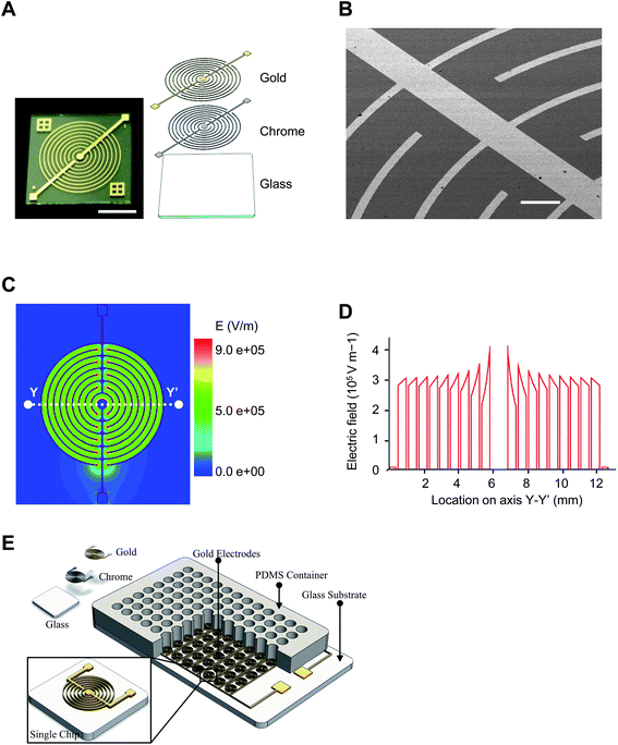 | ||
| Fig. 1 Electroporation microchip and electrotransfection procedures. (A) Schematic view of electroporation microchip fabricated by standard MEMS technology. The microchip consists of two juxtaposed chrome and gold layers sputtered on a glass substrate. Scale bar 5 mm. (B) SEM image of electrode. The electrode is 0.3 μm high and 100 μm wide throughout the microchip; inter-electrode distance is 500 μm. Scale bar 500 μm. (C) Simulated electrical field distribution under an applied voltage of 150 V. (D) Cross-sectional distribution of electrical field along line YY' in panel C. (E) Multiple-well electroporation design. | ||
Electroporation microchips were fabricated by a micromachining process consisting of sputtering, lithography, and wet etch. A 4-inch Pyrex7740 glass wafer was used as substrate, since it has high resistivity and transparency. Gold and chrome served as functional and adhesive materials for the microelectrodes, respectively. Gold was wildly used in biological applications because of its high conductivity, good chemical stability and non-toxicity. The electrode was sputtered and patterned on the glass substrate by simple one-mask lithography and wet etch. The thicknesses of the gold layer and chrome layer are 300 nm and 30 nm, respectively. The detailed fabrication process is presented in ESI S2.† An obvious advantage of our design is the simple fabrication process, which means low cost and broad prospects of commercialization.
Experimental procedures
Electrotransfection procedures are depicted schematically in Fig. 2. Briefly, cultured cells were harvested and re-suspended to a density of 3 × 10³cells/μl in a modified Eppendorf hypo-osmolar buffer (25 mM KCl, 0.3 mM KH2PO4, 0.85 mM K2HPO4, 36 mM myo-inositol, pH 7.2, conductivity 3.5 mS cm−1 at 25 °C). Plasmid DNA or siRNA was then added to a final concentration of 20 μg ml−1 or 4 pmole/μl respectively. For each electrotransfection, 20 μl of the mixture was loaded onto one microchip, treated with electrical pulses delivered by a YC-2 stimulator (Chengdu Instrument, China). Immediately after electroporation, 200 μl of normal culture medium was added into each well. Twenty-four hours later, the number of GFP-expressing cells was counted in five randomly chosen areas, under a fluorescence microscopy (Olympus). Surviving cells were assessed by propidium iodide exclusion assay. For each transfection, efficiency was calculated by dividing the number of GFP-expressing cells by the number of living cells, while the viability ratio was obtained by comparing the number of living cells between treated and untreated samples. Presented data are the average of three independent assays.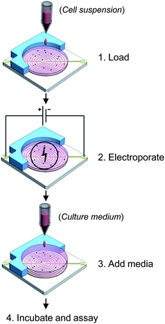 | ||
| Fig. 2 Electrotransfection procedures. Sequential loading, electroporation and culture procedures in electrotransfection. | ||
Oligonucleotides, plasmids, and cell culture
DNA oligonucleotides used for vector construction and quantitative RT-PCR were from Invitrogen (Beijing, China), and siRNA oligonucleotides were from Genepharma (Shanghai, China). The oligonucleotide sequences are presented in ESI S1.†Transfection efficacy of plasmid DNA was determined by using pEGFP-C3 plasmid encoding an enhanced green fluorescent protein (Clontech). Purifications of plasmid DNA were performed using an EndoFree Plasmid Maxi Kit (Qiagen, German).
HEK-293, Hela, HepG2, MDCK, and neuro-2A cells were grown in DMEM culture medium supplemented with 10% fetal bovine serum, 100 units/ml penicillin and 100 μg ml−1streptomycin (Life Technologies, Gibco). HL-60 cells were grown in RPMI-1640 culture medium with 10% FBS and antibiotics. PC-12 cells were grown in RPMI-1640 supplemented with 10% horse serum (Gibco) and 5% FBS. HUVECs were maintained in M199 culture medium supplemented with 20% FBS (Hyclone), antibiotics, 5 ng ml−1FGF (Sigma-Aldrich), and 80 μg ml−1heparin (Sigma-Aldrich).
Cell transfection by commercial systems
Electrotransfection by the Multiporator system (Eppendorf) or Neon Transfection System (Invitrogen) were performed according to the manufacturer's instructions. In Multiporator transfection, HEK-293 cells were electroporated in a cuvette with a 0.4 mm gap, with three pulses of 300 V for 50 μs. In Neon transfection, HUVECs were treated with a single pulse of 1350 V for 30 ms, in a 100 μl electroporation tip.RNAi assay
Human embryonic kidney cells (HEK293) were grown in Dulbecco's modified Eagle's medium supplemented with 10% fetal bovine serum, 2 mM L-glutamine, 100 units/ml penicillin and 100 μg ml−1streptomycin (Life Technologies,Gibco). The cells were seeded into 24-well plates at a density of ∼1 × 10⁵cells/well one day before transfection. Using Lipofectamine 2000 or the electroporation device, co-transfection of siQuant and pRL-TK vector (0.17 or 0.017 μg/well respectively) was performed, with or without siRNA (13 nM final concentration). The activity of both luciferases was determined by a fluorometer (Synergy HT, BioTek,USA) before the firefly luciferase activity was normalized to the renilla luciferase for each well. The silencing efficacy of each siRNA was calculated by comparison with a sample without siRNA treatment. All experiments were performed in triplicate and repeated at least twice.Results and discussion
Microchip electrotransfection system
In developing a highly efficient and universal gene delivery system, planar electroporation microchips consisting of patterned electrodes formed on a glass substrate were designed and produced with standard microfabrication technology (Fig. 1, ESI S2†). Four representative types-PF, SIF, AIF and RDF microchips are illustrated in Fig. 3. To mimic conventional cuvette-type electrotransfection devices, a pair of parallel electrodes spaced at 4 mm was fabricated in the PF microchip. By contrast, arrays of parallel electrodes with a much shorter inter-electrode distance (0.5 mm) were fabricated in the SIF and AIF microchips, producing a uniform electrical distribution across the whole microchip. In comparison with the AIF and SIF microchips, the large inter-electrode distance of the PF microchip however required high-strength electrical pulses for efficient gene delivery, resembling cuvette-type devices. Distinct from the parallel electrode design, a circular anode and a central cathode were fabricated in the RD microchip, producing a radial electrical field. Field strength decreases along the radius from the center, forming equipotential rings of decreasing intensity.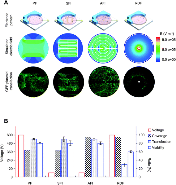 | ||
| Fig. 3 Performance of electroporation microchips. (A) Four types of electroporation microchip and cell electrotransfection. PF, parallel formatted microchip; SFI, square formatted interdigitated microchip; AFI, angular formatted interdigitated microchip; RDF, ring-dot formatted microchip. Electrical field distribution was simulated using the finite element method and FEA software. Cell transfection was assessed by GFP expression under fluorescence microscopy. (B) Electrotransfection performance of the microchips. Twenty-four hours after electroporation, the number of GFP-expressing cells was counted at five randomly chosen regions; the number of living cells was determined by PI exclusion. Voltage and pulse strength were optimized for efficient transfection on each microchip. Coverage, percentage area under electroporation; Transfection, transfection rate estimated by the number of transfected cells against living cells; Viability, viability rate estimated by the number of living cells between treated and untreated samples. Voltage is indicated on the left vertical axis, while the coverage, transfection, and viability rate are indicated on the right vertical axis. | ||
Under individually optimized conditions, a GFP-expressing plasmid was electroporated into HEK-293 cells cultured on the microchips, in a modified Eppendorf hypo-osmolar buffer. Twenty-four hours after treatment, successfully transfected cells were determined by GFP expression under a fluorescence microscopy, while dead cells were identified by PI exclusion staining. With the exception of the RDF microchip, generally high transfection efficacy and superior cell viability were obtained. As expected, uniform plasmid delivery was achieved in the parallel electroporation microchips, reflecting the even electrical field distribution. Notably, compared with the PF microchip, a 10-fold decrease in pulse strength was demonstrated for the interdigitated microchips. This improvement not only circumvents the many adverse effects of conventional devices, but also greatly decreases the pulse generator cost. When used with standard cell culture plates, the AFI microchip is preferred to the SFI microchip due to its high electroporation coverage, >95% of the cells in the culture well are subjected to electroporation using this microchip. For the AFI microchip, excellent cell viability (80%) and transfecting rate (90%), both much higher than those in previously reported methods, were achieved. Therefore, the AIF microchip was used in subsequent experiments.
Interestingly, a characteristic transfection pattern was observed with the RD microchip. While cells within a circular region were successfully transfected by reporter plasmid, all cells inside this ring were killed by the treatment, and cells outside the ring survived but without transfection. In consideration of the uneven field distribution, this phenomenon likely indicates that the optimal intensity was achieved within the circular transfection region, while higher intensities inside the ring killed the cells, and lower intensities outside the ring did not induce efficient transfection. This provides direct evidence that local field intensity is a major determinant in electrotransfection. Furthermore, when we treated different cell types using the same conditions, a distinct transfection ring was seen, likely due to the cell type-specific property.
Mechanisms essential for cell electrotransfection
In contrast to the suspension cell electrotransfection implemented in conventional cuvette-type devices, a prominent feature of microchip systems is that they enable in situ transfection. Cells remain in their original location during and after treatment, thus providing an opportunity to dissect the mechanisms involved in the electroporation process. When cells cultured on a microchip were treated by electrical pulsing, dead cells were seen to cluster around the cathode (Fig. 4A), suggesting the involvement of cathode-specific events. In order to elucidate the mechanism underlying this phenomenon, the effects of pulse strength and duration were assessed in terms of hydrolysis, as monitored by a pH indicator. Experimental data suggested that, compared with pulse strength, pulse duration is a more critical determinant of hydrolysis as well as cell mortality, and further suggested that shorter pulses are desirable in cell electroporation (Fig. 4B).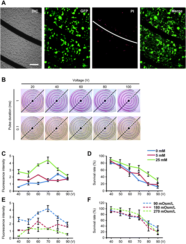 | ||
| Fig. 4 Effects of electroporation parameters. (A) Fluorescent and differential interference contrast image of electroporated cells. (B) Using phenolphthalein as an indicator, pH variations in chip electroporation were visualized under different conditions. Cell viability was therefore examined in terms of pulsing duration, strength and buffer pH value. (C, D) Graphic representation of cell transfection and viability as a function of buffer ionic strength. Buffer ionic strength was adjusted with KCl, and inositol was added to keep the buffer osmolarity unchanged between samples. (E, F) Graphic representation of cell transfection and viability as a function of buffer osmolarity. Buffer osmolarity was adjusted with inositol. | ||
Buffer ionic strength and osmolarity are major parameters determining cell viability in electroporation. In many cases, buffers of low ionic strength and therefore low conductivity are used in order to avoid the cell damage caused by buffer heating. In the present study, the effects of buffer ionic strength and osmolarity were examined (Fig. 4C–F). While the ionic strength and osmolarity were shown to play essential roles in transfection, marginal effects were found in cell viability, a critical bottleneck in mammalian cell electrotransfection. Remarkably, cell viability was inversely correlated with pulse strength, demonstrating the advantages of the chip electrotransfection system in enabling efficient cell transfection by low-voltage pulse treatment.
Electrotransfection of synthetic siRNA
RNAi has become an important technology for manipulating cellular phenotypes, understanding gene functions, and discovering novel therapeutic targets.3,16,17 However, owing to their large size and high adverse charge, siRNA delivery remains problematic. To determine the utility of microchips in siRNA delivery, a Lamin A/C siRNA was first electroporated into easy-to-transfect HEK-293 cells. For comparison, Lipofectamine 2000 and a commercial electrotransfection device (Multiporator, Eppendorf) were included in the experiments.18 Twenty-four hours after electroporation, expression levels of Lamin-AC were quantified by RT-PCR and western blot (Fig. 5A and B). As expected, 71% of target gene knock-down resulted from Lipofectamine transfection, which was similar to the level of chip electrotransfection. However, siRNA delivery by Multiporator did not show any silencing effect (Fig. 5B). Notably, a dose-dependent effect was observed in chip electrotransfection (Fig. 5A). Furthermore, co-transfection of plasmid DNA and synthetic siRNA were performed in HEK-293 cells. An active siRNA targeting firefly luciferase was electroporated into the cells together with a luciferase-expressing plasmid, and the resulting gene silencing was determined by dual-luciferase assay as previously described.19,20 Significant target gene repression demonstrated simultaneous transfection of both plasmid DNA and siRNA (Fig. 5C).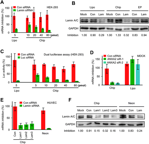 | ||
| Fig. 5 Electrotransfection of synthetic siRNA mediates potent gene silencing. (A, B) Lamin A/C siRNA of varying concentrations was electroporated into HEK-293 cells by chip electrotransfection, in which two square pulses of 70 V and 0.1 ms duration were applied. The expression of Lamin A/C was quantified at the mRNA (A) and protein levels (B). As controls, Lipofectamine 2000 transfection was included in the mRNA assay, and Multiporator electrotransfection was included in the protein assay. (C) Co-transfection of a luciferase-expressing vector and a luciferase-targeting siRNA into HEK-293 cells was carried out by chip electrotransfection and Lipofectamine transfection. The resulting gene silencing was quantified by dual-luciferase assay. (D) Two ANXA2 siRNAs were delivered into MDCK cells by chip electrotransfection and Lipofectamine transfection. For chip electrotransfection, three pulses of 150 V and 0.6 ms at an interval of 2 ms were applied. Gene expression level was quantified by RT-PCR. (E, F) Lamin A/C siRNA was electroporated into primary HUVECs by chip and Neon electrotransfection. Electroporation conditions are: Con, pulse strength 125 V and duration 0.1 ms; Lam1, 125 V, 0.1 ms; Lam2, 150 V, 0.1 ms; Lam3, 150 V, 0.2 ms; Neon, 1350 V, 30ms. Quantitative assays were performed at the mRNA (E) and protein levels (F). | ||
We next targeted the difficult-to-transfect MDCK cells by chip electrotransfection and Lipofectamine transfection. In comparison with Lipofectamine transfection, substantially potent RNAi effects were produced by chip electrotransfection (Fig. 5D). A sequence-irrelevant siRNA control was included in the experiment to exclude off-target gene silencing effects.
Although cultured cells serve as important models for understanding basic biological processes, primary cells are physiologically closer to the real biological systems and have greater potential in biomedical studies. The Lamin A/C siRNA was therefore transfected into primary HUVECs by chip electrotransfection, with a recently marketed electrotransfection device as the control (Neon Transfection System, Invitrogen).21 Quantitative RT-PCR and western blot revealed similar levels of target gene repression by both instruments (Fig. 5E and 5F). Strikingly, the optimal pulse strength was reduced from 1350 V for Neon electrotransfection to 125 V for chip electrotransfection. Lipofectamine transfection was omitted in this case because it results in low transfection efficacy and cytotoxicity in HUVECs.
A universal gene delivery platform
Co-transfection of plasmid and siRNA indicates that siRNA transfection can be monitored by plasmid transfection under a fluorescence microscopy, providing a simple way to evaluate siRNA delivery. To test the flexibility of chip electrotransfection, plasmid DNA was thus electroporated into a range of cell types representing different levels of difficulty in gene delivery. Suspension and in situ electrotransfection were first carried out in HEK-293 cells. For suspension electrotransfection, HEK-293 cells were collected, re-suspended in electroporation buffer, loaded onto the microchip, and then treated immediately with three pulses of 75 V and 0.1 ms duration. For in situ electrotransfection, cells in normal culture medium were loaded onto the microchip, and allowed to grow for 24 h before electroporation. Transfection efficacy of 90% and cell viability over 80% were obtained for both procedures (Fig. 6). In comparison with in situ electrotransfection, higher intensities and longer pulse durations were needed for efficient suspension electrotransfection. This, on the one hand, reflects the different status of the cells, and on the other hand, demonstrates the advantages of in situ electrotransfection.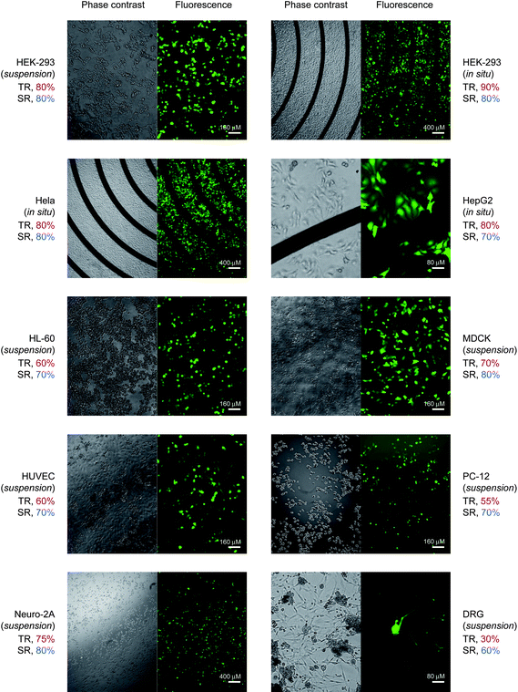 | ||
| Fig. 6 Universal gene delivery platform. pEGFP plasmid was electroporated into cultured and primary cells. TR, transfection rate; SR, survival rate. Individually optimized electroporation conditions for each cell type: suspension HEK-293 cells, pulse strength 75 V, duration 0.2 ms; adherent HEK-293 cells, 70 V, 0.1 ms; Hela cells, 60V, 0.1 ms; HepG2 cells, 60 V, 0.4 ms; HL-60 cells, 100 V, 0.2 ms; MDCK cells, 150 V, 0.6 ms; HUVECs, 75 V, 0.1 ms; PC-12 cells, 80 V, 0.1 ms; Neuro-2A cells, 80 V, 0.1 ms; DRG neurons, 80 V, 0.1 ms. Three pulses at an interval of 2 s were delivered in electroporation. | ||
With high degrees of transfection accompanied by low cell mortality, we successfully transfected several physiologically important cell types, particularly neurons and primary cells that are refractory to most transfection strategies (Fig. 6). These cells were HepG2 cells, a human hepatoma cell line retaining significant characteristics of the differentiated cell type; HL-60 cells, differentiated human promyelocytic leukemia cells; MDCK cells, a cocker spaniel-derived kidney cell; primary human umbilical vein endothelial cells (HUVECs); PC-12 cells, a pheochromocytoma cell line derived from rat adrenal medulla and often used in neuronal differentiation studies; Neuro-2A cells, a neuroblastoma cell line; and rat primary DRG neurons. Pulse conditions were individually optimized for a balance between transfection efficiency and cell viability. Twenty-four hours after treatment, EGFP expression was visually checked for transfected cells and PI exclusion staining was performed to visualize the dead cells. In comparison with published studies,22,23 higher transfection efficiency and viability were obtained, depending on the cell type. Particularly for DRG neurons, known to be refractory to existing transfection techniques, transfection efficacy of 30% and cell viability of 60% were obtained. Taken together, the optimal and consistent transfection indicates that microchip-mediated gene delivery efficiently targets extensive cell populations without cytotoxicity.
Membrane integrity of neurons after chip electrotransfection
In cell electroporation, elevated trans-membrane potential induced by extraneous electrical pulses leads to a rearrangement of the molecular structure of the cell membrane, pore formation and finally increased membrane permeability. The compromised integrity of the cell membrane very likely interferes with its normal activities, which is particularly important to cells whose physical functions are membrane-dependent such as DRG neurons. The DRG cell is a pseudo-unipolar neuron that plays a role in signal transmission from the peripheral to the central nervous system. After receiving sensory input at its endings, the DRG cell fires action potentials which travel along the afferent fiber to the cell body and axonal terminals, triggering transmitter release that can be monitored in real time using the patch-clamp technique.24 To evaluate the effect of chip electroporation on the physical condition of the cell membrane, freshly isolated rat DRG neurons were electroporated with an EGFP-expressing plasmid. Three days later, membrane capacitance and current were successfully recorded by patch-clamp on EGFP-expressing cells. The electrophysiological properties were similar to those of untreated cells, demonstrating that chip electrotransfection does not compromise the physiological functions of the cell membrane (ESI S3†).High-throughput practice of chip electrotransfection
A multiwall-format electroporation microchip was further designed and fabricated to achieve high-throughput electrotransfection (Fig. 7A and 7B). The prototype consisted of a 12-well electroporation strip and a matching flexiPERM cell growth chamber (Greiner). HEK-293 cells were seeded and cultured in each well one day before electroporation of a firefly luciferase-expressing plasmid, and resulted in reproducible transfection across the whole strip (Fig. 7C). | ||
| Fig. 7 Performance of multi-well electroporation strip. (A) Photograph of a 12-well electroporation strip and a matched flexiPERM cell culture chamber. Mounting the chamber onto the strip forms a standard 12-well cell culture plate. (B) Simulated electrical field distribution. (C) Gene silencing efficacies of firefly luciferase-targeting siRNA was determined in a co-transfection assay. | ||
Conclusion
A number of strategies have been established for gene delivery into living cells, including classic chemically-mediated transfection, pseudo-virus-facilitated gene delivery,25 microinjection26 and electrotransfection.27,28 Distinct from the passive gene delivery strategies, electrotransfection is achieved by applying high-strength electrical pulses to target cells, which temporarily increases the permeability of the cell membrane and allows trans-membrane delivery of macromolecules. The use of high-voltage pulses also causes many undesirable effects such as hydrolysis, pH turbulence and buffer heating. These adverse effects lead to increased cell mortality and so far limit its applications in mammalian cells (ESI S4 and S5†). To circumvent these problems, a microchip-based electrotransfection strategy was described.29,30 In the present study, we implemented an annular interdigitated electrode design. In comparison with available systems, this microchip design features significantly reduced inter-electrode distance, a parallel electrode pattern, and compatibility with standard cell culture plates. These improvements make it possible to achieve efficient cell transfection with low-strength pulses, provide a universal gene delivery platform, and further facilitate in situ high-throughput practice amenable to primary cells.Acknowledgements
This work was supported by the National Natural Science Foundation of China (30873187, 30771085 and 30871385), the Beijing Natural Science Foundation (5092011), the National High-tech R&D Program of China (2006AA02Z104 and 2007AA02Z165), the National Basic Research Program of China (2007CB512100), the National 985 Program, and grants from the Department of Education of China (20070001011 and 20090001110052). We appreciate Drs. Iain C. Bruce, Chunmei Cao and Xi Zhang for critically reading this manuscript. We are grateful to Dr Jincai Luo for providing HUVECs.References
- S. M. Elbashir, J. Harborth, W. Lendeckel, A. Yalcin, K. Weber and T. Tuschl, Nature, 2001, 411, 494–498 CrossRef CAS.
- T. A. Brooks and L. H. Hurley, Nat. Rev. Cancer, 2009, 9, 849–861 CAS.
- A. de Fougerolles, H. P. Vornlocher, J. Maraganore and J. Lieberman, Nat. Rev. Drug Discovery, 2007, 6, 443–453 CrossRef CAS.
- A. Eguchi, B. R. Meade, Y. C. Chang, C. T. Fredrickson, K. Willert, N. Puri and S. F. Dowdy, Nat. Biotechnol., 2009, 27, 567–571 CrossRef CAS.
- K. A. Whitehead, R. Langer and D. G. Anderson, Nat. Rev. Drug Discovery, 2009, 8, 129–138 CrossRef CAS.
- P. L. Felgner, T. R. Gadek, M. Holm, R. Roman, H. W. Chan, M. Wenz, J. P. Northrop, G. M. Ringold and M. Danielsen, Proc. Natl. Acad. Sci. U. S. A., 1987, 84, 7413–7417.
- M. Jordan, A. Schallhorn and F. M. Wurm, Nucleic Acids Res., 1996, 24, 596–601 CrossRef CAS.
- Y. C. Lin, M. Li and C. C. Wu, Lab Chip, 2004, 4, 104–108 RSC.
- K. S. Huang, Y. C. Lin, C. C. Su and C. S. Fang, Lab Chip, 2007, 7, 86–92 RSC.
- M. Olbrich, E. Rebollar and J. Heitz, et al., Appl. Phys. Lett., 2008, 92, 901–913.
- T. Jain and J. Muthuswamy, Lab Chip, 2007, 7, 1004–1011 RSC.
- J. K. Valley, S. Neale and H. Y. Hsu, Lab Chip, 2009, 9, 1714–1720 RSC.
- W. C. Chang and D. W. Sretavan, Biosens. Bioelectron., 2009, 24, 3600–3607 CrossRef CAS.
- H. He, D. C. Chang and Y. K. Lee, Bioelectrochemistry, 2008, 72, 161–168 CrossRef CAS.
- C. P. Jen, W. M. Wu and M. Li, J. Microelectromech. Syst., 2004, 13, 947–955 CrossRef CAS.
- D. Bumcrot, M. Manoharan, V. Koteliansky and D. W. Sah, Nat. Chem. Biol., 2006, 2, 711–719 CrossRef CAS.
- D. H. Kim and J. J. Rossi, Nat. Rev. Genet., 2007, 8, 173–184 CrossRef CAS.
- S. Gonzalez, D. Castanotto, H. Li, S. Olivares, M. C. Jensen, S. J. Forman, J. J. Rossi and L. J. Cooper, Mol. Ther., 2005, 11, 811–818 CrossRef CAS.
- Q. Du, H. Thonberg, H. Y. Zhang, C. Wahlestedt and Z. Liang, Biochem. Biophys. Res. Commun., 2004, 325, 243–249 CrossRef CAS.
- H. Huang, R. Qiao, D. Zhao, T. Zhang, Y. Li, F. Yi, F. Lai, J. Hong, X. Ding, Z. Yang, L. Zhang, Q. Du and Z. Liang, Nucleic Acids Res., 2009, 37, 7560–7569 CrossRef CAS.
- J. A. Kim, K. Cho, M. S. Shin, W. G. Lee, N. Jung, C. Chung and J. K. Chang, Biosens. Bioelectron., 2008, 23, 1353–1360 CrossRef CAS.
- K. S. Huang, Y. C. Lin, C. C. Su and C. S. Fang, Lab Chip, 2007, 7, 86–92 RSC.
- A. T. Prechtel, N. M. Turza, A. A. Theodoridis, M. Kummer and A. Steinkasserer, J. Immunol. Methods, 2006, 311, 139–152 CrossRef CAS.
- L. Y. Huang and E. Neher, Neuron, 1996, 17, 135–145 CrossRef CAS.
- D. L. Pettit, T. Koothan, D. Liao and R. Malinow, Neuron, 1995, 14, 685–688 CrossRef CAS.
- A. K. Banga, Expert Opin. Drug Delivery, 2009, 6, 343–354 Search PubMed.
- K. Kinosita, Jr. and T. Y. Tsong, Nature, 1977, 268, 438–441 CAS.
- H. D. Liang, J. Tang and M. Halliwell, Proc. Inst. Mech. Eng. H., 2010, 224, 343–361 Search PubMed.
- J. A. Kim, K. Cho, Y. S. Shin, N. Jung, C. Chung and J. K. Chang, Biosens. Bioelectron., 2007, 22, 3273–3277 CrossRef CAS.
- Y. C. Lin, M. Li, C. S. Fan and L. W. Wu, Sens. Actuators, A, 2003, 108, 12–18 CrossRef.
Footnotes |
| † Electronic supplementary information (ESI) available: Supplementary data S1 to S6. See DOI: 10.1039/c0lc00195c |
| ‡ These authors contributed equally to the work. |
| This journal is © The Royal Society of Chemistry 2011 |
