Three-dimensionally crossing manifold micro-mixer for fast mixing in a short channel length†
Tae Woo
Lim
a,
Yong
Son
a,
Yu Jin
Jeong
a,
Dong-Yol
Yang
*a,
Hong-Jin
Kong
b,
Kwang-Sup
Lee
c and
Dong-Pyo
Kim
d
aDepartment of Mechanical Engineering, Korea Advanced Institute of Science & Technology, Science Town, Daejeon, 305-701, South Korea. E-mail: dyyang@kaist.ac.kr; Fax: +82-42-350-3210; Tel: +82-42-350-3214
bDepartment of Physics, Korea Advanced Institute of Science & Technology, Science Town, Daejeon, 305-701, Korea
cDepartment of Polymer Science and Engineering, Hannam University, Daejeon, 306-791, Korea
dDepartment of Fine Chemical Engineering and Chemistry, Graduate School of Analytical Science and Technology, Chungnam National University, Daejeon, 305-764, Korea
First published on 11th October 2010
Abstract
In this study, we report a neo-conceptive three-dimensionally (3D) crossing manifold micromixer (CMM) embedded in microchannel. Fabricated by sequential processes of photolithography and two photon absorption stereolithography, this leads to a microfluidic system with a built-in micromixer in a site controlled manner. The effectiveness of CMM is investigated numerically and experimentally. Through the numerical simulation, it is estimated that a high mixing ratio of 90% can be obtained even in a channel length shorter than five times the channel width. This compares well with the conventional passive type of micromixers that have a gradual increase in mixing efficiency with the length of the channel. Furthermore, the mixing performance of the realized CMM built-in microchannel is observed by confocal microscopy.
Introduction
Recently, various mixing structures and fabrication processes have been developed to increase the mixing efficiency, which are generally classified into two types of active type and passive type according to the presence of an external power source for the operation of a micromixer.1–13 Compared to the active type mixer, the passive type is a simpler mixing technique because the mixing of fluids is induced only by the structural design that guides the fluids, without relying on a complicated moving part or external power source.1–10 Various passive type mixers have been developed based on simple fabrication processes and smart design of microchannels inducing convection flow or a large interface: bas-relief patterns on the floor of the microchannels inducing three-dimensional twisting flow,3 a split and recombine structure,1,5,6 and a Tesla structure.7 However, these methods require many mixing steps and a long channel-length of several centimetres for complete mixing, since the conventional fabrication methods are based on repetition of a 2D patterning process which limits the complicated design of the mixing structures for effective mixing. Recently, there have been some attempts to apply 3D lithography processes to the fabrication of highly-functional microfluidic components built in microchannels. 3D nano-porous structures using proximity field nanopatterning have shown that a high mixing efficiency can be obtained in a short channel length of several millimetres.8,9 However, the nano-porous microstructure has some shortcomings because it is not a structure designed for the purpose of effective micromixing. It can be susceptible to clogging, due to the very small dimensions of the flow paths, and it can create significant pressure drops. The effective design and fabrication of a micromixer for high mixing efficiency is still a challenge.In this paper, we propose a new design concept for a crossing manifold micromixer (CMM) which is a three-dimensionally designed microstructure with a sequential configuration of horizontally and vertically crossing tube bundles. The paper begins by describing the fabrication process of the CMM embedded microfluidic system. The channel patterns are fabricated by using a photolithography process. In order to produce the CMM built-in to the microchannels, we used a two-photon stereolithography process which is a useful process for fabricating arbitrary 3D microstructures with sub-100 nm resolution at a specific site.14–17 The mixing effectiveness of the developed microcomponents is comparatively investigated by observing the laminar flow characteristics using a confocal microscopy as well as by numerical analysis.
Crossing manifold micro-mixer
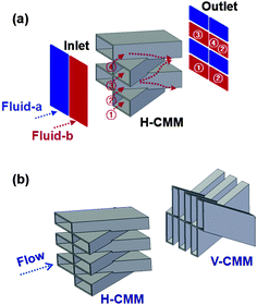
The proposed passive-type micromixer, the crossing manifold micromixer (CMM), has a configuration of layered crossing tubes that guide and realign fluids effectively. Fig. 1(a) illustrates the horizontally crossing manifold micromixer (H-CMM) and its mixing mechanism. Two fluids, fluid_a and fluid_b, are rearranged alternately in the vertical direction by the H-CMM. In contrast with the conventional split–recombine technique requiring many steps of mixing structures, many interfaces can be induced by increasing the number of manifolds in the single mixing structure of H-CMM. In addition to the effect of split–recombine, the momentum of fluids after the H-CMM is one of the dominant mixing mechanisms. The fluids passing inside the tubes have momentum left and right, and the fluids passing outside the tubes have momentum up and down. The momentum would also contribute to increase the mixing efficiency within a certain distance after the mixer. | ||
| Fig. 1 Schematic diagrams of (a) the mixing mechanism of the horizontally crossing manifold micromixer (H-CMM), and (b) horizontally and vertically crossing manifold micromixers (H/V-CMM). By aligning H-CMM and V-CMM sequentially in a microchannel, two fluids are three-dimensionally split and recombined. | ||
In order to design a more effective mixing structure, it is worth speculating that the mixing tendency of H-CMM would be enhanced if the fluids were realigned alternately in the layered direction of H-CMM. Our system proposes that the mixing efficiency can be dramatically improved by designing a sequentially aligned mixing structure incorporating H-CMM and a vertically crossing manifold micromixer (V-CMM) as shown in Fig. 1(b), designated as H/V-CMM. Laterally divided two laminar flows are rearranged vertically by H-CMM, and the vertically aligned fluids are repeatedly split and recombined at many sections in proportion to (the layer number of H-CMM) × (the layer number of V-CMM). An excessive number of tubes for high mixing efficiency leads to long fabrication time and high pressure drop because of overall thickness of the tubes. Thus, the hybrid H/V-CMM design is more favorable approach to increase the mixing effectiveness, rather than increasing the number of tubes in single H-CMM design.
Fabrication
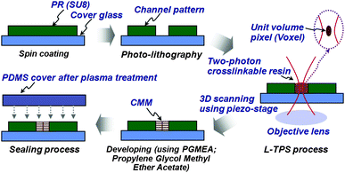
Fig. 2 shows the entire process for the fabrication of a microchannel with CMM. Firstly, a microchannel pattern was fabricated by a conventional photolithography process. The negative photoresist (SU8 3035, MicroChem) was spin-coated on a cover glass at 2000 rpm for 30 s. A prebaking process was then performed at 95 °C for 10 min. After UV exposure of 200 mJ cm−2 on the photomask with the microchannel pattern, it was post-baked at 95 °C for 10 min for the cross-linking process. The pattern is developed using propylene glycol methyl ether acetate and rinsed using isopropyl alcohol. Finally, a microchannel with a 50 μm height and width was obtained. | ||
| Fig. 2 The entire process for the fabrication of a microchannel with a crossing manifold micromixer (CMM). | ||
In order to fabricate the 3D microstructure in the microchannel, a large-area two-photon stereolithography (L-TPS) was employed.14 A two-photon crosslinkable resin is dropped in a microchannel on a cover-glass plate. The cover glass is fixed on the x, y, z piezoelectric stages. A mode-locked Ti:Sapphire laser beam is tightly focused with an objective lens (NA 1.4 × 100, immersion oil used) in the resin. 3D scanning of the focus in the resin is conducted by using the piezoelectric stages with a resolution of 0.1 nm. The fabrication area in the x, y directions, which depends only on the moving range of the stages, is 800 × 800 μm. The location of the 3D built-in microstructures in the x, y, and z directions is controlled by detecting the image using the CCD camera with the resolutions of 100 nm and 300 nm in x-y and z directions, respectively. The two-photon cross-linkable SU-8 resin was employed for both the channel patterns and the built-in 3D structures due to its durable mechanical properties and interfacial affinity. It took 4 h with a scanning speed of 100 nm ms−1 for the fabrication of the H/V-CMM in a microchannel with a cross-section of 50 μm × 50 μm. From the viewpoint of practical applications, the prolonged processing time in the direct laser writing processes based on the pin-point scanning method is one of the essential obstacles. However, the processing time could be improved by developing effective scanning processes such as multi-focus scanning and dynamic-mask lithography.18–20
After fabrication of the microstructures in the channel, the microfluidic system was sealed by bonding with polydimethylsiloxane (PDMS) slabs with two inlet and one outlet holes, after O2 plasma treatment under conditions: 0.1 Torr, 20 W, and 2 min.
Simulation and experimental validation
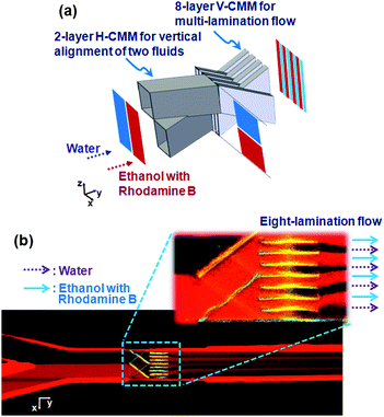
Confocal microscopy (Carl Zeiss, Inc., LSM510 META) was employed to observe the mixing behavior of the embedded micromixer in the sealed microfluidic system. The experiments were conducted in a microchannel with the cross-section of 50 μm × 50 μm, two fluids of deionized (DI) water and ethanol with dye (rhodamine B of 0.1 M concentration), and a total flow rate of 0.003 ml min−1 (a Reynolds number (Re) of 1 and a Péclet number (Pe) of 1000).First, a sequentially aligned H-CMM of a double layered tube structure and a V-CMM of eight layers were verified for simple observation of multi-laminar flow by a single H-CMM from a top view. Fluids initially divided horizontally are only realigned vertically without increased segments by the H-CMM of two layers, and are then rearranged into eight horizontally divided segments as shown in Fig. 3(a). Fig. 3(b), displaying the top view at half-height of the microchannel, shows a multi-layered stream produced by the CMM structure. It could be confirmed that multi-laminar flow providing many interfaces between the fluids is generated simply by a single CMM structure. Abrupt distortion of the stream line was observed near the CMM, and the multi-layered stream was sustained over a long distance of 6 mm until reaching the outlet.
 | ||
| Fig. 3 (a) Schematic illustration of a 2 layer H-CMM and 8 layer V-CMM for the simple observation of multi-laminar flow. (b) Top view of the mixing performance at the middle height of the channel. 8 segments of fluids are observed after the 2 layer H-CMM and 8 layer V-CMM. Ethanol with rhodamine B (0.1 wt%) and water flow from left to right; the red color is the fluorescence of the dye. | ||
In order to validate the effectiveness of the proposed micromixer, a H/V-CMM with six layered tube structures was investigated numerically and experimentally. Fig. 4 shows the simulation results (CFD ACE+, ESI group) displaying the cross-sectional views in the flow direction. The mixing efficiency rapidly increased as the distance from the H-CMM increased. From the cross-sectional images between H-CMM and V-CMM, it is observed that the fluids at each segment after H-CMM do not maintain their shapes completely due to the momentum of the fluids at the outlet of the mixing structure. The momentum, which is induced when the fluids pass through the mixing structure, is non-uniform and different at each segment. Therefore, according to the momentum, the shapes of the segments are deformed after H-CMM as shown in Fig. 4. A little convection and an increase of the area of interface also contributed to the increase of mixing efficiency, however, the amount of the increase differs according to factors of the design of the CMM, such as the crossing angle. By considering the intensively mixing region of H-CMM, V-CMM was set at the distance of 50 μm from H-CMM. It was found that the two fluids are split into 36 segments by H/V-CMM and finally distributed homogenously with 90% mixing efficiency at only 200 μm from the H-CMM, which corresponds to a length scale of four times the channel width. The channel length required for complete mixing in the H/V-CMM is surprisingly short even for a large Pe, compared to the several mm channel required for conventional passive type mixers. A higher mixing efficiency was observed for lower Pe since the mixing mechanism of the CMM is mainly based on multi-laminar flow. In addition, H/V-CMM is very advantageous from a pressure drop viewpoint since only a small fraction, 15% of the channel cross sectional area, is blocked by the manifolds. A very small pressure drop was observed during the complete mixing; the pressure drop was 970 Pa for the flow rate of 0.003 ml min−1, and was linearly dependent on the flow rate.
 | ||
| Fig. 4 Mixing efficiency vs. distance from H/V-CMM of six layers. The distance between the H-CMM and V-CMM is 50 μm. Under a flow rate of 0.003 ml min−1 (a Reynolds number of 1 and a Péclet number of 1000), the two fluids were almost completely mixed in a short channel length of five times the channel width. The mixing efficiency η is calculated using the inserted equation in which, c is a ratio of water in a unit area, c∞ is the ratio after perfect mixing, and c0 is the initial ratio. | ||
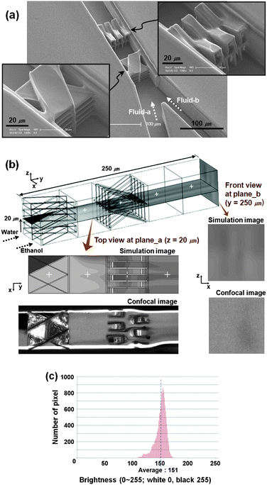
Fig. 5 shows an SEM image of the H/V-CMM fabricated in the microchannel, and experimental results. The wall thickness of the tube framework (1 μm) was designed to for stability from possible distortion of the CMM structure by the surface tension of the rinse solution in developing process. Fig. 5(b) shows gray-scale images of simulation and experimental results of the H/V-CMM; the white color is the fluorescence of the dye. Ethanol with dye flows from right to left after the H-CMM, and it is then distributed uniformly after H/V-CMM. In order to obtain the mixing efficiency, the confocal image at plane_b in Fig. 5(b) is transformed into a 256 bitmap file, and the brightness at each pixel is counted as shown in Fig. 5(c), which can be conveniently used as an engineering approximation of mixing efficiency. A mixing ratio of 93.9% is obtained from the standard deviation, which is a little higher than that of the simulation result (90%). According to the channel size, an optimized design would be required which considered the mixing ratio and pressure drop. The optimization of the proposed mixer outlined and further experimentation with the mixers are worthwhile.
 | ||
| Fig. 5 (a) SEM images of the H/V-CMM fabricated in the microchannel. A dead zone of fluids is observed in the triangle region between the manifolds and the side wall of the channel. It is formed by the accumulated dose between the structures. However, the dead zone is not significantly large, and it would be resolved by reducing the laser power. (b) Gray-scale images of simulation and experimental results. Ethanol with rhodamine B (0.1 wt%) and water flow from left to right; the white color is the fluorescence of the dye. (c) The number of pixel vs. the distribution of brightness of the confocal image at plane_b in Fig. 5(b). | ||
Conclusion
A new structural passive micromixer, termed a crossing manifold micromixer (CMM), was proposed for fast mixing in a short channel. The mixing mechanism and the effectiveness of the CMM were estimated using numerical analysis. A horizontally and vertically crossing manifold micromixer (H/V-CMM) of six layers was designed by considering the results of numerical analysis. Under those conditions, almost complete mixing of 90% could be estimated in the channel length of 250 μm, which was five times the channel width.A microchannel with a CMM was fabricated using photolithography and large-area two-photon stereolithography sequentially. The effectiveness of a CMM was confirmed by analysis of the flow of two fluids, ethanol with a fluorescent dye and water. It is to be hoped that this paper will contribute to the observation of instant chemical reactions, or high integration of micro total analysis systems (μ-TAS) and lab-on-a-chip.
Acknowledgements
This work is supported by Nano R&D program through the National Research Foundation of Korea funded by the Ministry of Education, Science and Technology (20090082831). One of us, K.-S. Lee would like to thank support of the National Research Foundation (No. R11-2007-050-00000-0).Notes and references
- J. Branebjerg, P. Gravesen, J. P. Krog and C. R. Nielsen, Proc. IEEE Micro Electro, 1996, 441–446 Search PubMed.
- R. H. Liu, M. A. Stremler, K. V. Sharp, M. G. Olsen, J. G. Santiago, R. J. Adrian, H. Aref and D. J. Beebe, J. Microelectromech. Syst., 2000, 9, 190–197 CrossRef.
- A. D. Stroock, S. K. Dertinger, A. Ajdari, I. Mezic, H. A. Stone and G. M. Whitesides, Science, 2002, 295, 647–651 CrossRef CAS.
- S. J. Park, J. K. Kim, J. Park, S. Chung, C. Chung and J. K. Chang, J. Micromech. Microeng., 2004, 14, 6–14 CrossRef.
- F. Schönfeld, V. Hessel and C. Hofmann, Lab Chip, 2004, 4, 65–69 RSC.
- D. S. Kim, S. H. Lee, T. H. Kwon and C. H. Ahn, Lab Chip, 2005, 5, 739–747 RSC.
- C. C. Hong, J. W. Choi and C. H. Ahn, Lab Chip, 2004, 4, 109–113 RSC.
- S. Jeon, V. Malyarchuk, J. O. White and J. A. Rogers, Nano Lett., 2005, 5, 1351–1356 CrossRef CAS.
- S. G. Park, S. K. Lee, J. H. Moon and S. M. Yang, Lab Chip, 2009, 9, 3144–3150 RSC.
- A. P. Sudarsan and V. M. Ugaz, Proc. Natl. Acad. Sci. U. S. A., 2006, 103, 7228–7233 CrossRef CAS.
- R. H. Liu, R. Lenigk, R. L. Druyor-Sanchez, J. N. Yang and P. Grodzinski, Anal. Chem., 2003, 75, 1911–1917 CrossRef CAS.
- L. H. Lu, K. S. Ryu and C. Liu, J. Microelectromech. Syst., 2002, 11, 462–469 CrossRef CAS.
- D. S. Kim, S. W. Lee, T. H. Kwon and S. S. Lee, J. Micromech. Microeng., 2004, 14, 798–805 CrossRef CAS.
- T. W. Lim, Y. Son, D. Y. Yang, H. J. Kong, K. S. Lee and S. H. Park, Appl. Phys. A: Mater. Sci. Process., 2008, 92, 541–545 CrossRef CAS.
- S. Maruo and H. Inoue, Appl. Phys. Lett., 2007, 91, 084101 CrossRef.
- M. Stoneman, M. Fox, C. Y. Zeng and V. Raicu, Lab Chip, 2009, 9, 819–827 RSC.
- D. Wu, Q. D. Chen, L. G. Niu, J. N. Wang, J. Wang, R. Wang, H. Xia and H. B. Sun, Lab Chip, 2009, 9, 2391–2394 RSC.
- J. Kato, N. Takeyasu, Y. Adachi, H. B. Sun and S. Kawata, Appl. Phys. Lett., 2005, 86, 044102 CrossRef.
- R. Nielson, B. Koehr and J. B. Shear, Small, 2009, 5, 120–125 CrossRef CAS.
- S. Matsuo, S. Juodkazis and H. Misawa, Appl. Phys. A: Mater. Sci. Process., 2005, 80, 683–685 CrossRef CAS.
Footnote |
| † Published as part of a LOC themed issue dedicated to Korean Research: Guest Editors: Professor Je-Kyun Park and Kahp-Yang Suh |
| This journal is © The Royal Society of Chemistry 2011 |
