Titanate nanosheets and nanotubes: alkalinity manipulated synthesis and catalyst support application
Zheng
Chang
,
Jing
Liu
,
Junfeng
Liu
and
Xiaoming
Sun
*
State Key Laboratory of Chemical Resource Engineering, Beijing University of Chemical Technology, P.O. Box 98. Beijing, 100029, P. R. China. E-mail: sunxm@mail.buct.edu.cn
First published on 22nd October 2010
Abstract
Titanate nanosheets (TiO-NS) and nanotubes (TiO-NT) were prepared under hydrothermal or solvothermal conditions in varied alkali solutions following similar procedures. Relatively low alkalinity (5M NaOH) was associated with TiO-NS, but high alkalinity (10M) resulted in TiO-NT. Addition of low-boiling point organic solvents could increase the reproducibility of TiO-NT, and sometimes lower the alkalinity needed for nanotubes formation. The two nanomaterials were used to load Pd nanoparticles to study their morphology-dependence as catalyst supports. The Pd-loaded titanate nanosheets (Pd/TiO-NS) showed higher activity than the Pd-loaded nanotubes (Pd/TiO-NT) in CO catalytic oxidation reactions. High resolution transmission electronic micrography (HRTEM) revealed much better dispersion of the supported Pd nanoparticles on nanosheets than nanotubes. The better catalytic performance of Pd/TiO-NS was believed to be related to less aggregation of the Pd nanoparticles on TiO-NS.
1 Introduction
In recent years, the nanocatalysis field has undergone an explosive growth.1 The researchers synthesized nanocrystals with well-defined shape and crystal faces, and used them for exploration of the relationship between structures and catalytic properties.2–4 However, the structure effects of catalyst supports are relatively rarely investigated although it is well-known that catalytic activity of catalysts is close to the character of catalyst supports5,6 and it has been proven that the surface structure and surface active sites of catalysts have a direct relationship with crystal faces of their supports.7,8Nanotubes and nanosheets can be candidates as catalyst supports.9–11 But usually nanotubes are considered more ideal catalyst supports due to their regular nanoporous structure, high special surface area and crystallinity. Indeed, carbon nanotubes (CNTs) have been widely studied as supports for nanoscopic metal catalysts, and some synergetic or confinement effects have been observed.12–14 As a counterpart of CNTs, graphene one-atom-thick sp2-bonded carbon nanosheets have been investigated as supports to disperse metal nanoparticles (e.g.Au, Pt) and improve their catalytic performance in catalytic reactions including oxygen reduction and methanol oxidation.15–19 In spite of vast investigations on nanostructure dependence of catalyst supports, e.g.nanotubesvs.nanosheets, different nanostructures were usually processed from various synthetic systems (e.g.hydrothermal synthesisvs.chemical vapor deposition). This made it complicated to identify the source of catalytic performance difference.
Titanate nanostructures (e.g.nanotubes and nanosheets) have attracted wide attention20–25 primarily owing to their cation-exchange capacity26 and have been investigated in various fields, such as catalysts, gas sensors, hydrogen storage, Li-ion batteries, and solar batteries.27 Among many potential applications, their use as catalyst supports has been explored for different catalytic purposes26,28–30 but mostly aimed at titanate nanotubes. Laura Torrente-Murciano et al.28 reported the preparation of Au, Pt, Ru, Ni, and Pd supported on multiwalled titanate nanotubes and Pd(II)/titanate nanotube catalysts had high activity and very high selectivity toward double-bond migration during the isomerisation of allylbenzene. Edisson Morgado Jr et al.26 investigated the nanostructured titanate as a precursor support for NiMo hydrotreating catalyst and the derived catalyst showed higher yields of ring opening of tetralin. In contrast, the sheet-like conterparts were usually prepared from high temperature solid state reaction and consequent exfoliation process,31 and merely used as building blocks for assembly of hybrid multilayer films and microporous materials with inorganic pillars,32 but not as catalyst support.
In this paper, we systematically investigated titanate nanotubes (TiO-NT) and titanate nanosheets (TiO-NS) synthesis conditions, and got pure samples by one-pot solvothermal method in similar solvent systems. The titanate nanostructures (nanotubesvs.nanosheets) thus provided ideal materials for a study on morphology-dependence as catalyst supports. The raw and Pd-loaded TiO-NT and TiO-NS were respectively characterized using CO oxidation as probing reactions. The catalytic properties demonstrated that titanate nanosheets were better than tubelike analogues as catalyst supports and thus provided a possible better support for catalytic applications in the future. This was believed to be relative to less aggregation of Pd nanoparticles on TiO-NS.
2 Experimental
2.1 Controlled synthesis
The method employed for synthesis of titanate nanosheets was essentially similar with titanate nanotubes described in reference 33. In a typical procedure, 0.4 g of TiO2 powder with an average diameter size of 4 nm prepared using the method reported34 was dispersed in 40 mL, 5 ∼ 8 M NaOH (A.R. grade) aqueous solution. For titanate nanotubes, the volume of NaOH aqueous solution was gradually reduced from 40 to 10 mL, and 0 ∼ 30 mL alcohol or another organic solvent (cyclohexane, N-pentane, benzene, toluene, THF, butanol, hexanol, acetone, ether, ethyl acetate) was respectively supplied to maintain an invariable volume sum of 40 mL. The resulting suspension was stirred for 10 min and then transferred into a 40 mL Teflon-lined stainless autoclave, sealed, and maintained at 140 °C for 48 h. The resulting white precipitate after natural cooling in air was filtered, washed with deionized water, and finally dried at 60 °C.Loading of Pd nanoparticles on TiO-NS or TiO-NT was performed by a reflux method using alcohol as reductant.35 In a typical procedure, 0.5 g titanate nanostructures were dispersed in the mixture of 30 mL water and 20 mL alcohol aided by ultrasonication for 10 min, and refluxed for 30 min. 0.03 g PdCl2 was dissolved in 2 mL diluted HCl aqueous solution (pH = 3) and then added dropwise to the above suspension. The resulting mixture was stirred and refluxed for 1 h before cooled to room temperature. The product was collected after filtration, rinsed with water and alcohol for 3 circles respectively and drying at 80 °C for 4 h.
2.2 Characterization
The powder X-ray diffraction (XRD) patterns were recorded on a Bruker D8 advanceddiffractometer under the following conditions: 40 kV, 30 mA, Cu-Kα radiation (λ = 0.15418 nm). Transmission Electron Microscopy (TEM) was performed using Hitachi 800 and JEM JEOL2010Felectron microscopes running at 200 kV. The specific surface areas were measured on a QuantaChrome ABSORB-1 gas sorption analyzer from Micromeritics after outgassing the samples at 60 °C for 3 h. The pore size distributions were determined using BJH model.CO catalytic oxidation was used as a probe reaction to measure catalytic activities of the raw and Pd-loaded titanate nanostructures. CO oxidation was evaluated in a fixed-bed reactor at atmospheric pressure using 400 mg of catalysts. Temperature programmed reaction was performed with 100 mL min−1 of gas flow (1 vol% CO; 16 vol% O2; balance N2). The reaction temperature was monitored by a thermocouple placed in the middle of the catalyst bed. The catalyst was directly exposed to reaction gas at the reactor temperature without any pretreatment. CO concentration in the reactor effluent was analyzed using an Agilent 6850gas chromatograph equipped with a TCD detector. The conversion was calculated on the basis of CO2 production.
3 Results and discussion
3.1 Controlled synthesis of titanate nanostructures
The effects of different preparation conditions on the morphologies of titanate nanostructures were studied, such as concentration of NaOH, mass of TiO2, type and volume of inert organic solvent. Preparation conditions and morphologies were shown in Fig. 1, 2 and 3, and summarised in Table 1.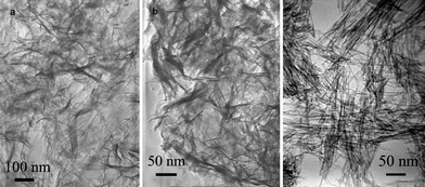 | ||
| Fig. 1 TEM micrographs of titanate nanostructures prepared in pure aqueous solutions with different NaOH concentration: (a) 5 M, (b) 8 M, (c) 10 M. | ||
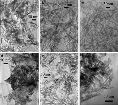 | ||
Fig. 2
TEM micrographs of titanate nanostructures prepared in various conditions including different alcohol/water volume ratio, NaOH mass, and TiO2 mass: (a) alcohol![[thin space (1/6-em)]](https://www.rsc.org/images/entities/char_2009.gif) :water = 1:3, NaOH 8g, TiO2 0.4g; (b) alcohol:water = 3:5, NaOH 8g, TiO2 0.4g; (c) alcohol:water = 3:1 ,NaOH 4g, TiO2 0.2g; (d) alcohol:water = 3:5, NaOH 8g, TiO2 0.6g; (e) alcohol:water = 1:1, NaOH 8g, TiO2 0.6g; (f) cyclohexane:water = 3:5, NaOH 6g, TiO2 0.6g. :water = 1:3, NaOH 8g, TiO2 0.4g; (b) alcohol:water = 3:5, NaOH 8g, TiO2 0.4g; (c) alcohol:water = 3:1 ,NaOH 4g, TiO2 0.2g; (d) alcohol:water = 3:5, NaOH 8g, TiO2 0.6g; (e) alcohol:water = 1:1, NaOH 8g, TiO2 0.6g; (f) cyclohexane:water = 3:5, NaOH 6g, TiO2 0.6g. | ||
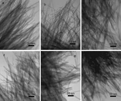 | ||
| Fig. 3
TEM micrographs of titanate nanotubes prepared in various organic solvents (organic solvent:water = 1:1, NaOH 8g, TiO2 0.4g): (a) cyclohexane; (b) benzene; (c) THF; (d) acetone; (e) ether; (f) hexanol. | ||
| NaOH/g | TiO2/g | H2O/mL | Organic solvent | Organic solvent/mL | V(organic solvent):V(H2O) |
Alkalinitya/M | Morphology |
|---|---|---|---|---|---|---|---|
| a alkalinity: calculated concentration of NaOH in only aqueous section: n(NaOH)/v(H2O). | |||||||
| 8 | 0.4 | 40 | Alcohol | 0 | 0 | 5 | Nanosheets |
| 8 | 0.4 | 30 | Alcohol | 10 | 1:3 |
7 | Nanosheets |
| 8 | 0.4 | 25 | Alcohol | 15 | 3:5 |
8 | Nanotubes |
| 8 | 0.4 | 20 | Alcohol | 20 | 1:1 |
10 | Nanotubes |
| 4 | 0.2 | 10 | Alcohol | 30 | 3:1 |
10 | Nanotubes |
| 8 | 0.6 | 25 | Alcohol | 15 | 3:5 |
8 | Nanosheets and nanotubes |
| 8 | 0.6 | 20 | Alcohol | 20 | 1:1 |
10 | Nanotubes |
| 6 | 0.6 | 25 | Cyclohexane | 15 | 3:5 |
6 | Nanotubes |
| 8 | 0.4 | 20 | Cyclohexane | 20 | 1:1 |
10 | Nanotubes |
| 8 | 0.4 | 20 | Butanol | 20 | 1:1 |
10 | Nanotubes |
| 8 | 0.4 | 20 | Hexanol | 20 | 1:1 |
10 | Nanotubes |
| 8 | 0.4 | 20 | Ether | 20 | 1:1 |
10 | Nanotubes |
| 8 | 0.4 | 20 | Acetone | 20 | 1:1 |
10 | Nanotubes |
| 8 | 0.4 | 20 | N-pentane | 20 | 1:1 |
10 | Nanotubes |
| 8 | 0.4 | 20 | Benzene | 20 | 1:1 |
10 | Nanotubes |
| 8 | 0.4 | 20 | Toluene | 20 | 1:1 |
10 | Nanotubes |
| 8 | 0.4 | 20 | THF | 20 | 1:1 |
10 | Nanotubes |
| 8 | 0.4 | 20 | Ethyl acetate | 20 | 1:1 |
10 | Nanotubes and little nanosheets |
Pure water was used as solvent for first stage investigation. 0.4 g TiO2 nanopowder was added into 5 M, 8 M and 10 M of NaOH aqueous solutions, respectively, and hydrothermally treated at 140 °C for 48 h. As shown in Fig. 1a–b, two samples both exhibited sheet-like structures. Several folded edges in them implied a tendency of rolling-up, without significant difference. This result revealed that when pure water was used as solvent, titanate nanosheets could be prepared in the relatively low concentrations of NaOH aqueous solutions (5 ∼ 8 M), which was consistent with the threshold concentration of NaOH in aqueous solution for titanate nanotubes (generally 10 M, as shown in Fig. 1c).33
Using alcohol/water as mixed solvent could significantly change the morphologies of final products (Fig. 2). In the fixed conditions (TiO2 0.4 g, NaOH 8 g, fixed total volume 40 mL), increasing the volume ratio of alcohol could lead to formation of nanotubes (Fig. 2 a–e). For alcohol:water = 1:3 (10 mL alcohol + 30 mL water) solution, the sample was mainly nanosheets, but as the ratio increased to 3:5 (15 mL alcohol + 25 mL water), quite pure nanotubes formed. Further study indicated that pure TiO-NT could form when the NaOH amount was halved (TiO2 amount was also halved to keep the reactant ratio unchanged) if the alcohol/water ratio was high enough (3:1). These results clearly revealed that increasing the volume proportion of alcohol favored the generation of nanotubes. Furthermore, we noticed that increasing the alcohol/water ratio had an equal effect with addition of NaOH amount. For instance, at alcohol:water = 3:5, increasing the TiO2 mass from 0.4 g to 0.6 g would lead to relative deficiency of NaOH and consequently sheet-like structures formed (Fig. 2d), about 50% of the total output. But increasing the alcohol/water ratio to 1:1 would recover the product to pure nanotubes (Fig. 2e).
As we know from aqueous synthesis, increase the concentration of NaOH could transform titanate nanosheets to nanotubes. The transformation threshold was ∼10 M (Fig. 1). Then, why do the titanate nanotubes form at much lower apparent NaOH concentration in the presence of alcohol? To illustrate the underlying roles, we summarized the data in Table 1 and re-defined ‘alkalinity’ as ‘the absolute concentration of NaOH in aqueous-only solution’. That is, [alkalinity] = n(NaOH)/v(H2O), ignoring the volume of organic solvent and calculating only the aqueous section. Viewing in this way, 16 g NaOH dissolved in 40 mL water would have equal alkalinity to 8 g NaOH dissolved in 40 mL alcohol:water = 1:1 mixed solution, and also equal to 4 g NaOH dissolved in 40 mL alcohol:water = 3:1 mixed solution. In all the 3 cases, pure TiO-NT samples formed because the alkalinities were high enough (10 M).
Furthermore, the experiments also suggested that the presence of alcohol reduced the threshold alkalinity for generation of TiO-NT to ∼8 M. As indicated by Fig. 2a, most products were sheet-like as the alkalinity was 6.67 M, but pure nanotube samples were prepared as the alkalinity was higher than 8 M. The results also implied that the threshold condition was dynamic. Increasing the mass of TiO2 to 0.6 g led to generation of TiO-NS, but increase the alkalinity by improving alcohol/H2O volume ratio made pure TiO-NT again (Fig. 2e). We chose another low-boiling point organic solvent, cyclohexane, a water inmiscibile solvent to check the effect. It was kind of unexpected that it had even more significant effect to improve the TiO-NT formation. At cyclohexane:water = 3:5 and 6 g NaOH (alkalinity was as low as 6 M), 0.6 g TiO2 was fully transformed to TiO-NT with purity >90%, as displayed in Fig. 2f. But at the same conditions, the mixed solvent of alcohol/water only gave ∼50% TiO-NT and ∼50% TiO-NS (Fig. 2e). All these results were summarized in Table 1.
Since mixing alcohol or cyclohexane with water helped to get reproducible synthesis of nanotubes, we chose some other common low-boiling point organic solvents to check the effect, including alcohol (ethanol, butanol, hexanol), ether (Et–O–Et), ester (ethyl acetate), ketone (acetone), alkanes (cyclohexane, N-pentane), benzene, toluene and THF. In all the cases, the alkalinities were kept at 10 M and the volume ratios of organic solvents to water were fixed at 1:1. The experimental data was shown in Table 1 and Fig. 3. As expected, high quality TiO-NT formed in most cases no matter if they were miscible with water or not, except those reactive to alkali (e.g.ethyl acetate, which underwent a hydrolysis reaction under basic conditions). The results unambiguously revealed that the way to calculate the alkalinity was suitable and low-boiling point organic solvents could improve the formation of TiO-NT. Considering so many kinds of solvents could work, the effect of organic solvents should associate with some common points of these solvents, like lowering the boiling point of mixture and the consequently increasing inner pressure as solvothermally treated, which possibly enhanced the imbalance force on different sides of sheet and led to rolling-up.36
3.2 Catalytic properties of titanate nanostructures
As we all know, catalytic properties of catalyst are inseparable to characteristics of catalyst support. Because titanate nanosheets and nanotubes showed almost identical crystal structures after the similar preparation processes, they provided ideal materials for the study on morphology-dependence as catalyst supports. CO catalytic oxidation was used as a probe reaction to estimate catalytic activities of the raw and Pd-loaded titanate nanostructures. The corresponding CO conversions were plotted in Fig. 4. For the raw nanomaterials, the catalytic activity of TiO-NT was higher than that of TiO-NS: the temperature at which CO conversion achieved more than 95% was 400 °C for TiO-NT (Fig. 4a) and it rose to 500 °C for TiO-NS (Fig. 4b); their initial temperatures at which CO began to transform were almost the same, about 280 °C, but the curve slope of CO conversion for TiO-NT was bigger, suggesting that its catalytic efficiency was higher. The morphologies of tube vs. sheet showed an obvious influence on catalytic activities of the titanate nanomaterials.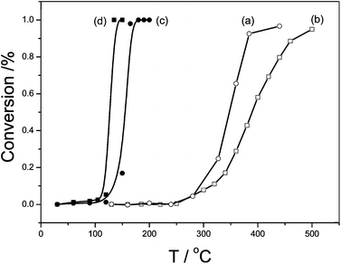 | ||
| Fig. 4 CO conversion curves on the raw and Pd-loaded titanate nanostructures: (a) TiO-NT(○), (b) TiO-NS(□), (c) Pd/TiO-NT(●), (d) Pd/TiO-NS(■). | ||
However, the morphology effect was just the opposite for the Pd-loaded samples. That is, the catalytic activity of Pd-loaded titanate nanosheets (Pd/TiO-NS) was higher than that of Pd-loaded titanate nanotubes (Pd/TiO-NT). In both cases, the Pd-loaded nanomaterials showed obviously higher activities than the raw samples, considering the complete CO oxidation temperatures changed from >400 °C to <200 °C. However, the complete conversion temperature for Pd/TiO-NT was 165 °C (Fig. 4c), while it decreased to 135 °C for Pd/TiO-NS (Fig. 4d). The catalysis results indicated that a good catalyst (i.e. supported catalysts with active components) doesn't have to have highly reactive supports, and some other intrinsic properties of the supports are more important.
To reveal the “intrinsic properties” that dominated the catalyst support performances, we checked our samples's crystallinity using XRD, and also their pore structure using nitrogen adsorption-desorption technique. XRD patterns of Pd/TiO-NT and Pd/TiO-NS, before and after CO catalytic oxidation reactions were shown in Fig. 5. The characteristic reflections of two titanate materials indicated that they had very similar crystal structures. The nanotube sample had even better crystallinity. After CO oxidation reactions, the titanate materials perfectly maintained their crystal structures and morphologies, which were demonstrated by the XRD patterns in Fig. 5 and TEM (data not shown). Moreover, the new characteristic peaks of Pd or PdO phase were absent. It was suggested that the contents of Pd component were low and Pd crystals did not obviously grow big even after catalytic reactions.
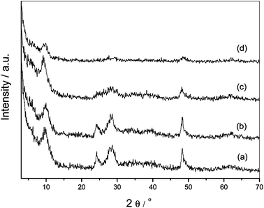 | ||
| Fig. 5 XRD patterns of the Pd-loaded titanate nanostructures before and after CO oxidation: Pd/TiO-NT (a) and after reaction (b), Pd/TiO-NS (c) and after reaction (d). | ||
Nitrogen adsorption-desorption experiments were carried out in order to determine the specific surface areas and pore size distributions of the raw titanate materials. The specific surface area of TiO-NS was ∼14 m2 g−1, much lower than that of its tubelike analogue (∼99 m2 g−1). The pore size distribution curve of TiO-NS showed a sharp peak in 3.7 nm which coincided with that of TiO-NT, which should correspond to a small amount of titanate nanotubes formed in preparation and preheatment steps before N2adsorption-desorption measurement.
It was concluded from the above analysis that a tubelike morphology had high surface area, regular pore size distribution, and improved crystallinity compared to titanate nanosheet. Then why the catalytic property was reversed after active component Pd was loaded? The reason was possibly attributed to different dispersion of Pd on titanate nanosupports, as revealed by HR-TEM analysis (Fig. 6). It was clearly observed that the loaded Pd nanoparticles on TiO-NT tended to assemble into clusters (Fig. 6a–b), but those loaded on TiO-NS exhibited much more discrete dispersion (Fig. 6c–d). So, it seemed the reason why TiO-NS worked as a better catalyst support for CO oxidation should be attributed to the better dispersion of Pd nanoparticles on nanosheets. The clustering of Pd nanoparticles on TiO-NT might relate to the rolling-up process, which accompanied with decrease of surface energy and loss of active sites. Furthermore, some Na+ ions in interlayers for stabilizing a tubelike structure could diffuse out slowly, leaving the titante framework protonated and making a local environment basic.33 It was proposed that possible formation of Pd(OH)2 precipitation led to Pd nanoparticles aggregate as loading on TiO-NT, though the precipitation converted to Pd clusters right away by the reduction of alcohol. Fortunately, this effect of Na+ could be lowered to a reasonable degree at the preparation process of Pd/TiO-NS because of a relatively low alkali environment.
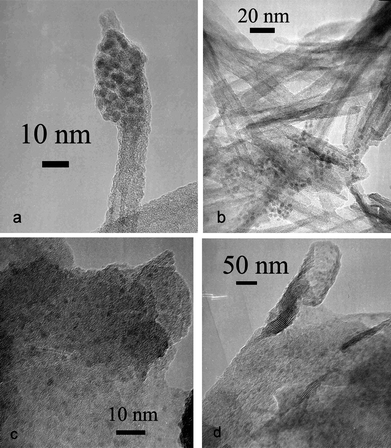 | ||
| Fig. 6 HR-TEM micrographs of Pd/TiO-NT (a–b) and Pd/TiO-NS (c–d). | ||
4 Conclusions
Controlled synthesis of titanate nanosheets (TiO-NS) and nanotubes (TiO-NT) were solvothermally realized in very alkali solutions of aqueous or mixed solvents. Absolute alkalinity was found to be a dominant factor controlling the morphology of final products. Addition of low-boiling point organic solvents improved the formation of titanate nanotubes using less alkali. As-formed nanosheets and nanotubes were used as supports for Pd loading. The Pd-loaded sheetlike catalyst (Pd/TiO-NS) had better dispersion of Pd nanoparticles, thus showed higher activity for CO oxidation in spite of smaller specific surface area and lower catalytic activity of the support. The results demonstrated that the degree of dispersion of the active components obviously influenced the performance of supported catalysts, even more so than the activity of support itself.Acknowledgements
This work was supported by the National Natural Science Foundation of China, the National Basic Research Program of China, the Foundation for the Author of National Excellent Doctoral Dissertation of P. R. China, the Program for New Century Excellent Talents in Universities, and the Project sponsored by SRF for ROCS, SEM, the Research Fund for Youth Scholars of Beijing University of Chemical Technology (NO.QN0812).References
- D. S. Wang, T. Xie and Y. D. Li, Nano Res., 2009, 2, 30–46 CrossRef CAS.
- R. Xu, D. S. Wang, J. T. Zhang and Y. D. Li, Chem.–Asian J., 2006, 1, 888–893 CrossRef CAS.
- K. B. Zhou, X. Wang, X. M. Sun, Q. Peng and Y. D. Li, J. Catal., 2005, 229, 206–212 CrossRef CAS.
- L. H. Hu, Q. Peng and Y. D. Li, J. Am. Chem. Soc., 2008, 130, 16136–16137 CrossRef CAS.
- G. A. Somorjai, Proceedings of the Robert A. Welch Foundation Conferences on Chemical Research, Houston, Texas, 1981, The surface science of heterogeneous catalysis, in: Heterogeneous Catalysis, vol. XXV, 1981, p83 Search PubMed.
- R. S. Monteirol, L. C. Dieguez and M. Schmal, Catal. Today, 2001, 65, 77–89 CrossRef CAS.
- J. F. Liu, W. Chen, X. W. Liu, K. B. Zhou and Y. D. Li, Nano Res., 2008, 1, 46–55 CrossRef CAS.
- W. Chrzanowski and A. Wieckowski, Langmuir, 1998, 14, 1967–1970 CrossRef CAS.
- M. E. Spahr, P. Bitterli, R. Nesper, M. Muller, F. Krumeich and H. U. Nissen, Angew. Chem., Int. Ed., 1998, 37, 1263–1265 CrossRef CAS.
- X. Wang and Y. D. Li, Chem. Lett., 2004, 33, 48–50 CrossRef.
- Y. D. Li, J. W. Wang, Z. X. Deng, Y. Y. Wu, X. M. Sun, D. P. Yu and P. D. Yang, J. Am. Chem. Soc., 2001, 123, 9904–9905 CrossRef CAS.
- S. M. Lee, K. H. An, Y. H. Lee, G. Seifert and T. Frauenheim, J. Am. Chem. Soc., 2001, 123, 5059–5063 CrossRef CAS.
- P. Serp, M. Corrias and P. Kalck, Appl. Catal., A, 2003, 253, 337–358 CrossRef CAS.
- X. L. Pan, Z. L. Fan, W. Chen, Y. J. Ding, H. Y. Luo and X. H. Bao, Nat. Mater., 2007, 6, 507–511 CrossRef CAS.
- Y. C. Si and E. T. Samulski, Chem. Mater., 2008, 20, 6792–6797 CrossRef CAS.
- S. Stankovich, D. A. Dikin, G. H. B. Dommett, K. M. Kohlhaas, E. J. Zimney, E. A. Stach, R. D. Piner, S. T. Nguyen and R. S. Ruoff, Nature, 2006, 442, 282–286 CrossRef CAS.
- R. Muszynski, B. Seger and P. V. Kamat, J. Phys. Chem. C, 2008, 112, 5263–5266 CrossRef CAS.
- R. Kou, Y. Y. Shao, D. H. Wang, M. H. Engelhard, J. H. Kwak, J. Wang, V. V. Viswanathan, C. M. Wang, Y. H. Lin, Y. Wang, I. A. Aksay and J. Liu, Electrochem. Commun., 2009, 11, 954–957 CrossRef CAS.
- Y. M. Li, L. H. Tang and J. H. Li, Electrochem. Commun., 2009, 11, 846–849 CrossRef CAS.
- T. Gao, Q. L. Wu, H. Fjellvåg and P. Norby, J. Phys. Chem. C, 2008, 112, 8548–8552 CrossRef CAS.
- Y. Zhou, R. Ma, Y. Ebina, K. Takada and T. Sasaki, Chem. Mater., 2006, 18, 1235–1239 CrossRef CAS.
- J. H. Choy, H. C. Lee, H. Jung and S. J. Huang, J. Mater. Chem., 2001, 11, 2232–2234 RSC.
- F. Kooli, T. Sasaki, V. Rives and M. Watanabe, Synthesis, J. Mater. Chem., 2000, 10, 497–501 Search PubMed.
- X. M. Sun, X. Chen and Y. D. Li, Inorg. Chem., 2002, 41, 4996–4998 CrossRef CAS.
- N. Masaki, S. Uchida and T. Sato, J. Mater. Chem., 2002, 12, 305–308 RSC.
- E.M. Jr, J. L. Zotin, M. A. S. de Abreu, D. O. Rosas, P. M. Jardim and B. A. Marinkovic, Appl. Catal., A, 2009, 357, 142–149 CrossRef.
- J. Huang, Y. Cao, Q. Huang, H. He, Y. Liu, W. Guo and M. Hong, Cryst. Growth Des., 2009, 9(8), 3632–3637 CrossRef CAS.
- L. Torrente-Murciano, A. A. Lapkina, D. V. Bavykin, F. C. Walsh and K. Wilson, J. Catal., 2007, 245, 272–278 CrossRef CAS.
- L. M. Sikhwivhilu, N. J. Coville, D. Naresh, K. V. R. Chary and V. Vishwanathan, Nanotubular titanate supported palladium catalysts, Appl. Catal., A, 2007, 324, 52–61 CrossRef CAS.
- J. S. Jang, S. H. Choi, D. H. Kim, J. W. Jang, K. S. Lee and J. S. Lee, J. Phys. Chem. C, 2009, 113, 8990–8996 CrossRef CAS.
- M. Gateshki, S. J. Hwang, D. H. Park, Y. Ren and V. Petkov, Chem. Mater., 2004, 16, 5153–5157 CrossRef CAS.
- T. Gao, H. Fjellvåg and P. Norby, J. Phys. Chem. B, 2008, 112, 9400–9405 CrossRef CAS.
- X. M. Sun and Y. D. Li, Chem.–Eur. J., 2003, 9, 2229–2238 CrossRef CAS.
- C. Wang, Z. X. Deng and Y. D. Li, Inorg. Chem., 2001, 40, 5210–5214 CrossRef CAS.
- T. Teranishi and M. Miyake, Chem. Mater., 1998, 10, 594–600 CrossRef CAS.
- S. Zhang, L. M. Peng, Q. Chen, J. H. Du, G. Dawson and W. Zhou, Phys. Rev. Lett., 2003, 91, 256103–256106 CrossRef CAS.
| This journal is © The Royal Society of Chemistry 2011 |