DOI:
10.1039/C0JM01523G
(Paper)
J. Mater. Chem., 2011,
21, 251-256
Assembly of an artificial biomembrane by encapsulation of an enzyme, formaldehyde dehydrogenase, into the nanoporous-walled silica nanotube–inorganic composite membrane†
Received
20th May 2010
, Accepted 7th September 2010
First published on 20th October 2010
Abstract
We prepared silica nanotube with nanochannel-wall in the columnar pores of a commercial anodic alumina membrane (F127-MST), and then made up an artificial biomembrane consisting of a hierarchical structure by introducing an enzyme, formaldehyde dehydrogenase, into the silica nanochannels. The formaldehyde dehydrogenase confined in membrane showed a very high activity for the reduction of NAD+ similar to that of the native, besides much higher electron transfer to the electrode than the native. At the same time, we clarified that the encapsulation of enzymes into the nanochannels enables enzymes to accumulate in high density without aggregation and be arranged regularly. These results indicate that F127-MST can provide a favorable method for enzyme immobilization on the electrode.
Introduction
Protein molecules have several independent functions in living systems. Among those functions, perhaps the most striking biochemical role is to affect the rates of a wide range of reactions that constitute the dynamic aspects of the life process in a specific and efficient manner. The fact that they are susceptible to a variety of controls is also one of their characteristics. Proteins having such catalytic activity are called enzymes, but enzymes have been neglected as catalysts in organic synthesis due to their high cost, contamination of products by residual proteins, and their low stability. However, the encapsulation of enzymes into a mesoporous silicate results in increased resistance to organic solvents, or their surroundings, in comparison with the native enzymes.1–11 In addition, since it is well-known that membrane proteins form an array of proteins and direct complicated reactions, membranes with enzymes can be very useful reactors for organic synthesis if enzymes are immobilized in the pores of an inorganic membrane. Based on this idea, the synthesis of nanoporous silica in anodic alumina pores has recently been tried elsewhere,12–17 and the resultant composite membranes have shown high potential as artificial membrane supports, owing to a large number of interconnected pores. In order for the artificial biomembrane to act effectively, the direction of the mesoporous silica channels becomes important. The prepared channels in the pores of a porous alumina membrane should have the same direction as that of alumina columnar pores, i.e., perpendicular to the face of base alumina membrane.12,13 Additionally, the size of pores is key, and in order to successfully separate proteins and substrates, the size of the channel must be large enough for only proteins to pass through. In our previous study, we successfully prepared a silica–alumina composite, with perpendicular channels (pore size = ca. 8 nm). Here, we present a more advanced silica–alumina composite, in terms of enzyme adsorption properties and electron transfer.
Results and discussion
In Fig. 1a, a schematic figure of a newly prepared silica–alumina composite membrane is shown. The biggest difference from the previous material is the existence of pores perpendicular to the face of the alumina membrane and additional nanochannels on the wall of perpendicular pores. By simply changing a surfactant and vacuuming condition, a different and more advanced material was obtained. In order to examine the structure of the composite, it was slightly etched with 10% phosphoric acid solution. SEM and STEM characterizations were done, as shown in Fig. 1b–f. Silica nanotubes with perpendicular channels (pore size = ca. 100 nm) grown in the alumina pores are seen in Fig. 1b and c. With higher resolution, the surface of each silica nanotube can be viewed (Fig. 1d), and more interestingly, a cross section of the nanotube along the channel is observed in Fig. 1e. Based on these SEM observations, each mesoporous silica nanotube is aligned perpendicular to the alumina membrane face, having an outer diameter of about 200 nm, which corresponds to the size of the alumina columnar pores. Both Fig. 1d and e have indicated the existence of nanochannels (ca.13 nm). With further observation using STEM (Fig. 1f), the nanochannel structure was determined as a 3D-hexagonal structure. The interesting structure of the new materials was effectively confirmed. The nanoporous-walled silica nanotube–alumina composite was newly obtained, and hereafter, we call this material F127-MST (F127-membrane with silica tube).
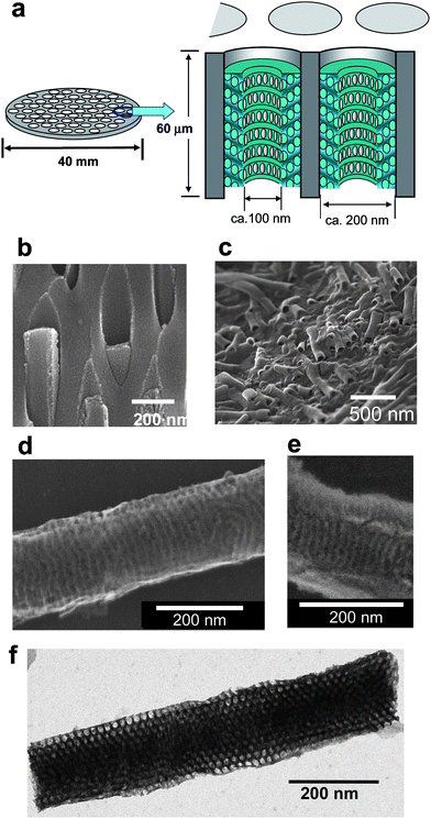 |
| | Fig. 1 (a) Schematic illustrations of the anodic alumina membrane and silica–alumina compositemembrabe. The assembly is made of silica nanotubes (inside tube diameter = ca.100 nm) with nanochannel-wall (channel diameter = ca. 13 nm) formed inside the columnar alumina pore (pore diameter = 200 nm). (b, c, d, e) Typical SEM images. Cross-sectional view of silica-alumina composite, showing silica nanorods grown in the alumina pores (b), silica–alumina composite after removal of alumina membrane (c), surface of a silica nanotube (d), and cross section of a nanotube along the channel (e). (f) Typical STEM image of columnar mesoporous silica (side-view). The silica material without alumina was obtained as a white precipitate by complete etching of the alumina membrane and collecting by filtration. | |
Owing to the interconnected pore structures, consisting of perpendicular pores (ca. 100 nm) nanochannel-wall (ca. 13 nm), the idea that mass transfer must be improved comes up. Then, a gas permeation test was performed. The set-up is shown in Scheme 2 and details of experiments are explained in the experimental section. During the test, when a single component helium was fed into the membranes, the helium permeances were approximately 8000,18 2000 and 50018 nmol m−2 s−1p−1, for the alumina base only (Fig. 2, curve A), for F127-MST (Fig. 2, curve B), and for silica–alumina composite only with perpendicular pores (ca. 8 nm) to the alumina base (NAM) (Fig. 2, curve C, see Fig. 1S in ESI† for a schematic image of NAM),18 respectively. This result indicates that the pores of the base membrane were narrowed because of the mesoporous silica formation inside. Furthermore, mass transfer was improved compared to a previous silica–alumina composite (NAM) because of additional nanochannels on the wall of the silica nanotube. To understand more details of mass transfer with F127-MST, binary mixtures of helium and water at 40 °C were tried. The resulting helium permeances are described in Fig. 2 as a function of the partial pressure of water. The permeance of the base membrane was constant at approximately 8000 nmol m−2 s−1 p−1 (curve A) but that of F127-MST and NAM decreased to 652 (curve B) and to 5.6 nmol m−2 s−1 p−1 (curve C), respectively, at a relative water pressure of 0.63. This result indicates that permeation of helium molecules is inhibited as the water vapor condenses in the silica pores. Even so, due to the existence of central large pore (ca. 100 nm), F127-MST is more tolerant to water vapor than NAM.
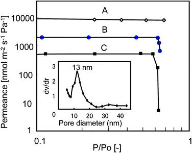 |
| | Fig. 2 The permeation properties of the anodic alumina membrane (curve A), F127-MST (curve B) and NAM (curve C)18 as a function of the partial pressure of water vapor in the feed stream for binary mixtures of helium and water vapor at 40 °C. Inset shows a pore size distribution plot calculated by nitrogen adsorption/desorption measurements. | |
As mentioned in introduction, confinement of enzymes into inorganic nanospaces leads to higher stabilization against environmental factors such as temperature, pressure, media, etc. Then, it is reasonable to expect the development of a high-performance artificial membrane accumulating enzymes confined in inorganic nanospaces, even though few reports of such membranes have been published to date.8,18–21 Here, we believe that F127-MST is a good candidate for production of an artificial biomembrane capable of accumulating enzymes and arranging them regularly. In this study, a particular enzyme, a formaldehyde dehydrogenase (FDH) from Pseudomonas sp, consisting of two subunits with a molecular weight of 150![[thin space (1/6-em)]](https://www.rsc.org/images/entities/char_2009.gif) 000 (size: ca. 8.5 × 8.5 × 19 nm; PDB (pdb:%3Ca%20href=), EC; 1.2.1.46),22 was chosen. It is reported that its activity was completely lost when the subunits dissociated to the individuals,23,24 so FDH is a good candidate in order to know if F127-MST works as an artificial membrane, which produces an array of enzymes inside the pores without dissociating. FDH was adsorbed into the pores of F127-MST by the procedure described in the experimental section, and then nitrogen adsorption/desorption measurements were done for the resulting composites (see Fig. 2S in ESI†). As a result, BET surface areas based on nitrogen adsorption/desorption measurements decreased after adsorption of FDH to F127-MST (Table 1). This suggests that FDH was encapsulated into the silica nanochannels, which was consistent with the previously reported data.3,9–11 We would like to make a note on the surface area and pore volume of F127-MST. They seem small compared to other mesoporous materials, but this is due to the structure of the alumina membrane. When the alumina membrane was removed, the surface area and pore volume increased (Table 1), and those values were comparable to those of other mesoporous silica.
000 (size: ca. 8.5 × 8.5 × 19 nm; PDB (pdb:%3Ca%20href=), EC; 1.2.1.46),22 was chosen. It is reported that its activity was completely lost when the subunits dissociated to the individuals,23,24 so FDH is a good candidate in order to know if F127-MST works as an artificial membrane, which produces an array of enzymes inside the pores without dissociating. FDH was adsorbed into the pores of F127-MST by the procedure described in the experimental section, and then nitrogen adsorption/desorption measurements were done for the resulting composites (see Fig. 2S in ESI†). As a result, BET surface areas based on nitrogen adsorption/desorption measurements decreased after adsorption of FDH to F127-MST (Table 1). This suggests that FDH was encapsulated into the silica nanochannels, which was consistent with the previously reported data.3,9–11 We would like to make a note on the surface area and pore volume of F127-MST. They seem small compared to other mesoporous materials, but this is due to the structure of the alumina membrane. When the alumina membrane was removed, the surface area and pore volume increased (Table 1), and those values were comparable to those of other mesoporous silica.
Table 1 Physicochemical properties of the FDH-(F127-MST)
| Compound |
FDH adsorbed (mg/100 mg F127-MST) |
Specific surface area (m2 g−1) |
Pore volume (cm−3 g−1) |
|
It was obtained as a white precipitate by complete etching of the alumina membrane with 10% phosphoric acid solution and collecting by filtration.
|
|
FDH-(F127-MST)
|
0 |
19.0 |
0.06 |
| 0.6 |
9.3 |
0.04 |
|
Alumina
membrane
|
— |
6.4 |
0.02 |
| F127-MSTa (without alumina) |
— |
516 |
1.02 |
Using FDH encapsulated F127-MST (FDH-(F127-MST)), a series of experiments were conducted to test whether formaldehyde was transported through the enzyme hybrid membrane and induce the reduction of NAD+, which was an important role as an artificial biomembrane. The set-up shown in Scheme 1 was in use. Then, the activities of FDH-(F127-MST) in aqueous solutions were determined by measuring the amount of NADH produced:
| | | HCHO + NAD+ + 3H2O –FDH→ HCOO− + NADH + 2H3O+ | (1) |
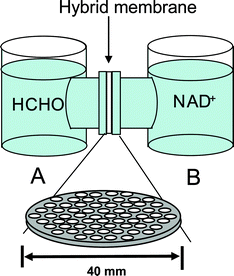 |
| | Scheme 1 A schematic illustration of substrate permeation and reaction test apparatus. | |
The amount of NADH was calculated by monitoring the absorbance increase at 340 nm using a molar extinction coefficient of ε 340 nm = 6.22 × 10³ M−1 cm−1. As shown in Scheme 1, the FDH-(F127-MST) was set between Cell A (50 ml of phosphate buffer (pH 7.4)) and Cell B (50 ml of NAD (9 × 10⁻⁴ M) in a phosphate buffer (pH 7.4)). Fig. 3 presents the production of NADH. When 4 ml of 3% formaldehyde was added to Cell A, absorbance at 340 nm by cell B increased sharply owing to the successful reduction of NADH (curve B). On the other hand, the absorbance of cell A increased only slightly (curve A). The results indicate that the formaldehyde is successfully transported through the enzyme hybrid membrane to induce the reduction of NAD+. Even though NAD+ flew back to Cell A side, the amount was small and main stream of formaldehyde from Cell A to Cell B side through the artificial biomembrane was achieved successfully.
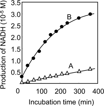 |
| | Fig. 3 Enzymatic activity of FDH-(F127-MST). It was spectrophotometrically determined by measuring the absorbance increase at 340 nm owing to the production of NADH by oxidation reaction of formaldehyde. Curve A: response from Cell A consisting of 50 ml of phosphate buffer (pH 7.4). Curve B: response from Cell B consisting of NAD+ (9 × 10⁻⁴ M) in 50 ml of phosphate buffer (pH 7.4). | |
As you can see, the reduction of NAD+ proceeds in a coupling reaction with oxidation of formaldehyde in the FDH-(F127-MST). That leads our next interest toward investigation of the electron transfer from NADH to electrode. Therefore, electrochemical experiments using FDH-(F127-MST) were conducted in order to examine whether electron transfer successfully proceeds in the presence of NAD+ and quinone as a mediator. The details of the electrochemical set-up are described in the experimental section and Fig. 4. The electron transfer from formaldehyde is based on the following sequence of reactions:
| | | HCHO + NAD+ + 3H2O –FDH→ HCOO− + NADH + 2H3O+ | (2) |
| | | H+ + NADH + Q → NAD+ + QH2 | (3) |
| | | QH2 –electrode→ Q + 2e− + 2H+ | (4) |
where FDH catalyses the oxidation of
formaldehyde to
formic acid, while NAD
+ is reduced to NADH. The sensitivity of
electrochemical detection depends on the efficiency of the electron transfer from NADH
viaquinone to the glassy carbon electrode. The typical responses of FDH-(F127-MST) (1.7 mg; FDH, 0.01 mg) in the presence of NAD
+ and
quinone are shown in
Fig. 5. As indicated in the figure, the current increased rapidly and reached a steady-state output (1 × 10
−7 A) within 100 s after the first injection of
formaldehyde (total: 1.4 ppm) into the electrolyte solution (curve A). After the second injection of
formaldehyde (total: 14 ppm), the current increased rapidly again and reached a steady-state output (8 × 10
−7 A). On the other hand, even after the second injection of
formaldehyde (total: 14 ppm), the response of native (FDH; 0.02 mg) in the solution was very low (0.12 × 10
−7 A) (curve B) although amount of native (FDH; 0.02 mg) was higher than that in FDH-(F127-MST) (1.7 mg; FDH, 0.01 mg). This indicates that an electrochemical mediator (
i.e.,
quinone) intermediates the electron transfer from the NADH to the carbon electrode effectively even in an environment where FDH was encapsulated in the pores of
silica nanochannels with a high-aspect ratio of F127-MST. Therefore, F127-MST enables high density accumulation of the enzyme without aggregation on the electrode.
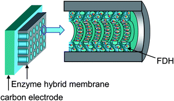 |
| | Fig. 4 A schematic diagram of the electrochemical cell setup. FDH is immobilized on carbon electrodes with FDH-(F127-MST). | |
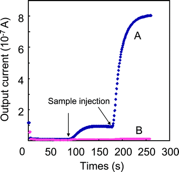 |
| | Fig. 5 Typical responses of (A) FDH–(F127-MST) (1.7 mg: 0.01 mg as FDH) and (B) native (0.02 mg as FDH) to the injections of a formaldehyde solutions (1.4 and 14 ppm) at a constant potential of Eapp = 0.35 V. The electrolytes comprise 0.63 mM NAD+ and 0.64 mM quinone in a 12 ml of phosphate buffer (pH 7.4). | |
Further, in order to look at the stability of enzyme, the activity of FDH-(F127-MST) was tested several times using the same sample. FDH-(F127-MST) electrode was washed in distilled water by using the wash-bottle three times after each measurement and the electrolyte solution in the cell was also exchanged with a fresh electrolyte solution each time. By using a 2.8 ppm of formaldehyde solution, the current response was measured 10 times, and the reproducibility to the original signal was plotted in Fig. 6. Even after 10 repetitive usage, the FDH–(F127-MST) material produced over 90% of the original signals. In other words, the current responses were almost reversible for 10 repetitive times. This high reusability results from that FDH was successfully encapsulated into the pores of FDH-(F127-MST) and was immobilized rigidly.
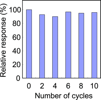 |
| | Fig. 6 Stability of enzymatic activity on FDH-(F127-MST) (1.7 mg: 0.01 mg as FDH). The current response was measured by injections of a formaldehyde solutions (2.8 ppm) at a constant potential of Eapp = 0.35 V. The electrolytes comprise 0.63 mM NAD+ and 0.64 mM quinone in a 12 ml of phosphate buffer (pH 7.4). | |
The immobilization of enzymes in supports commonly lowers their activity,1,2 but this is attributed to the fact that most reactants find it difficult to approach enzymes enclosed within the supports. Furthermore, enzymes sometimes change their conformation or structure, to a greater or lesser degree, when immobilized. However, in this study, such lowering of FDH activity was not observed, and FDH-(F127-MST), i.e., the artificial biomembrane, continued to show a very high capacity for the reduction of NAD+. This seems to be due to the fact that the protein barely changes its original structure with encapsulation,3,10 and also that the silica nanochannels still possess some margin for small molecules to pass and access enzymes freely, even after FDH encapsulation.
Conclusions
Silica
nanotubes inside the columnar pores of an anodic alumina membrane (F127-MST) was newly prepared, and the existence of nanochannels on the walls of silica nanotubes was confirmed. An artificial biomembrane was successfully produced by introducing an enzyme, FDH, into F127-MST. The encapsulation of the enzyme in the silica nanochannel-wall enabled high density accumulation of the enzyme without aggregation.
Experimental
Material characterization
SEM images (Fig. 1b and 1c) were measured with a field-emission SEM (JEOL JSM-6700). The sample membrane was fixed on the SEM stage using carbon tapes, and SEM measurements were performed after deposition of Pt/Pd thin layer using an ion-sputter (Vacuum Device Inc. Model MSP-10, Japan).
Similarly, SEM (Fig. 1d and 1e) and STEM (Fig. 1f) were measured on a Hitachi S-5200, but measurements were done without a metal coating at an acceleration voltage of 30 kV.
Preparation of F127-MST and FDH-(F127-MST)
The precursor solution containing a triblock copolymer surfactant (F127) was prepared according to the literature, with some modifications.12,18 A typical procedure for synthesis was as follows. The F127 (1.0 g) was dissolved in a mixture of ethanol (15 g), HCl (0.10 g of 37 wt% aqueous solution), and water (2.0 g). This mixture was stirred for 1 h at 60 °C in a flask with a reflux condenser. TEOS (2.13 g) was then added to the mixture, followed by further stirring for 17 h at 60 °C. The resulting mixture was immediately used as the precursor solution for the preparation of F127-MST in the following.
An anodic alumina membrane was set in an ordinary membrane filtration apparatus, and the precursor solution (4 ml) was dripped onto the alumina membrane. Rapid vacuuming was applied by using a diaphragm vacuum pump (20 L/min) (Model UN820, KNF Neuberger, Inc.), so that the precursor solution penetrated the columnar alumina pores. After the complete penetration into the alumina pores, the alumina membrane with the precursor solution was dried under aspiration for 10 min. The resulting sample was then calcined at 500 °C for 6 h in the air to obtain F127-MST.
FDH-(F127-MST) was prepared as follows. F127-MST as obtained in the previous paragraph was placed in a solution of 10.0 ml of FDH (EC. 1.2.1.46) (0–20 mg) dissolved in water. The membrane was then kept standing in that solution for 12 h at 4 °C to establish an adsorption equilibrium. The amount of FDH adsorbed into the pores of F127-MST was determined by measuring the absorbance of the supernatant at 280 nm, which was characteristic absorption band of FDH. Additionally, the successful adsorption was verified by the TG decline on the TG-DTA curves (Fig. 3S in ESI†). Furthermore, we dissolved only the alumina part of FDH-(F127-MST) by etching with phosphoric acid. The precipitate was collected by centrifugation. The amount of FDH detected by BCA method25 in the supernatant solution after centrifugation was below 10% of the amount of FDH used for adsorption onto F127-MST. The result suggested that over 90% of FDH introduced into F127-MST still existed in the nanochannel-wall of the silica nanotubes in alumina pores.
Gas permeation tests
Permeation properties through the membrane were determined for binary mixtures of helium and steam at 40 °C using the setup shown in Scheme 2.18,26 The membrane was connected to stainless steel flanges using a resin (Varian, Torr Seal). To reinforce the membrane, a porous mullite disk (Nikkato Corp., F, diameter = 25 mm, thickness = 2 mm, porosity = 22%) was placed between the permeate side of the membrane and the stainless steel flange. The membrane was fixed to a permeation cell using Teflon sealing rings. Water vapor was fed through the membrane by bubbling with helium, and so the composition of this mixture was adjusted. Most of the feed mixture did not permeate the membrane, but escaped from the cell. Argon was purged through the membrane from the permeate side as a sweep gas, and argon, permeated helium, and water vapor were evacuated from the cell. The composition of the feed and the permeated mixtures were analyzed by a gas chromatograph (GC-TCD, Agilent Technologies, A3000) equipped with PLOT-Q as a separation column. The flow rate of the mixture was determined by a flow meter.
The electrochemical cell VC-3 comprises a three-electrode setup,19 which was purchased from Bioanalytical Systems, Inc. (BAS, West Lafayette, USA). The potentiostat and the software were purchased from Hokuto Denko Corporation (Kanagawa, Japan). The electrodes consist of a glassy carbon working electrode (i.d.: 3 mm), a platinum auxiliary electrode, and an Ag/AgCl (+199 mV vs.NHE) reference electrode. The working electrode was constructed as follows. FDH–(F127-MST) (previously cut into 4 mm × 4 mm squares and washed in distilled water three times before use) was placed on the nylon mesh (pore diameter = ca. 1 μm, and thickness = ca. 75 μm). Then, it was placed directly on the working electrodesvia rubber O-rings. The electrochemical detection system was based on amperometric measurements. The cell was filled with an electrolyte solution (12 ml) containing NAD+ (0.63 mM) and quinone (i.e., 1,2-naphthoquinone-4-sulfonic acid) (0.64 mM) in a phosphate buffer (pH 7.4). The electrodes were dipped in this electrochemical cell with stirring and connected to a computer-controlled HSV-100 potentiostat. After incubation for 10 min, a potential of 0.35 V vs.Ag/AgCl was applied. Measurements of the samples were performed after the background current had settled (100 s). That is, 50 μl of formaldehyde standard solution (0.37%) in a phosphate buffer (pH 7.4) was injected into the cell by a micropipette. All measurements were performed at 25 ± 1 °C.
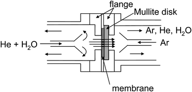 |
| | Scheme 2 A schematic illustration of gas permeation test apparatus. | |
Acknowledgements
The research was financially supported by the project at the Japan Science and Technology Agency (JST).
References
- S. Hudson, J. Cooney and E. Magner, Angew. Chem., Int. Ed., 2008, 47, 8582 CrossRef CAS.
-
(a) M. Hartmann, Chem. Mater., 2005, 17, 4577 CrossRef CAS;
(b) M. Hartmann and D. Jung, J. Mater. Chem., 2010, 20, 844 RSC.
- Y. Urabe, T. Shiomi, T. Itoh, A. Kawai, T. Tsunoda, F. Mizukami and K. Sakaguchi, ChemBioChem, 2007, 8, 668 CrossRef CAS.
- H. Takahashi, B. Li, T. Sasaki, C. Miyazaki, T. Kajino and S. Inagaki, Chem. Mater., 2000, 12, 3301 CrossRef CAS.
- J. Deere, E. Magner, J. G. Wall and B. K. Hodnett, Chem. Commun., 2001, 465 RSC.
- A. Vinu, V. Murugesan, O. Tangermann and M. Hartmann, Chem. Mater., 2004, 16, 3056 CrossRef CAS.
- J. Fan, J. Lei, L. Wang, C. Yu, B. Tu and D. Zhao, Chem. Commun., 2003, 2140 RSC.
-
(a) Y. Wang and F. Caruso, Chem. Mater., 2005, 17, 953 CrossRef CAS;
(b) Y. Wang and F. Caruso, Adv. Funct. Mater., 2004, 14, 1012 CrossRef CAS.
- T. Itoh, R. Ishii, T. Ebina, T. Hanaoka, Y. Fukushima and F. Mizukami, Bioconjugate Chem., 2006, 17, 236 CrossRef CAS.
- T. Itoh, R. Ishii, T. Ebina, T. Hanaoka, T. Ikeda, Y. Urabe, Y. Fukushima and F. Mizukami, Biotechnol. Bioeng., 2007, 97, 200 CrossRef CAS.
- T. Itoh, R. Ishii, S. Matsuura, S. Hamakawa, T. Hanaoka, T. Tsunoda, J. Mizuguchi and F. Mizukami, Biochem. Eng. J., 2009, 44, 167–173 CrossRef CAS.
- A. Yamaguchi, F. Uejo, T. Yoda, T. Uchida, Y. Tanamura, T. Yamashita and N. Teramae, Nat. Mater., 2004, 3, 337 CrossRef CAS.
- A. Yamaguchi, H. Kaneda, W. Fu and N. Teramae, Adv. Mater., 2008, 20, 1034 CrossRef CAS.
- Z. Yang, Z. Niu, X. Cao, Z. Yang, Y. Lu, Z. Hu and C. C. Han, Angew. Chem., Int. Ed., 2003, 42, 4201 CrossRef CAS.
- Q. Lu, F. Gao, S. Komarneni and T. E. Mallouk, J. Am. Chem. Soc., 2004, 126, 8650 CrossRef CAS.
-
(a) B. Platschek, N. Petkov and T. Bein, Angew. Chem., Int. Ed., 2006, 45, 1134 CrossRef CAS;
(b) N. Petkov, B. Platschek, M. A. Morris, J. D. Holmes and T. Bein, Chem. Mater., 2007, 19, 1376 CrossRef CAS.
-
(a) Y. Wu, G. Cheng, K. Katsov, S. W. Sides, J. Wang, J. Tang, G. H. Fredrickson, M. Moskovits and G. D. Stucky, Nat. Mater., 2004, 3, 816 CrossRef CAS;
(b) Y. Wu, T. Livneh, Y. X. Zhang, G. Cheng, J. Wang, J. Tang, M. Moskovits and G. D. Stucky, Nano Lett., 2004, 4, 2337 CrossRef CAS.
- T. Itoh, R. Ishii, T. Hanaokaa, Y. Hasegawaa, J. Mizuguchia, T. Shiomi, T. Shimomura, A. Yamaguchi, H. Kaneda, N. Teramae and F. Mizukami, J. Mol. Catal. B: Enzym., 2009, 57, 183 CrossRef CAS.
- T. Shimomura, T. Itoh, T. Sumiya, F. Mizukami and M. Ono, Sens. Actuators, B, 2008, 135, 268 CrossRef.
- T. Shimomura, T. Itoh, T. Sumiya, F. Mizukami and M. Ono, Talanta, 2009, 78, 217 CrossRef CAS.
- T. Shimomura, T. Itoh, T. Sumiya, F. Mizukami and M. Ono, Enzyme Microb. Technol., 2009, 45, 443 CrossRef CAS.
- M. Ando, T. Yoshimoto, S. Ogushi, K. Rikitake, S. Shibata and D. Tsuru, J. Biochem., 1979, 85, 1165 CAS.
-
H. R. Mahler, E. H. Cordes, in Biological Chemistry (Harper & Row, London, 1969) Search PubMed.
- J. Switala, J. O. O'Neil and P. C. Loewen, Biochemistry, 1999, 38, 3895 CrossRef CAS.
- C. M. Stoscheck, Methods Enzymol., 1990, 182, 50 CAS.
- Y. Hasegawa, T. Ikeda, T. Nagase, Y. Kiyozumi, T. Hanaoka and F. Mizukami, J. Membr. Sci., 2006, 280, 397 CrossRef CAS.
Footnote |
| † Electronic supplementary information (ESI) available: Further figures. See DOI: 10.1039/c0jm01523g |
|
| This journal is © The Royal Society of Chemistry 2011 |
Click here to see how this site uses Cookies. View our privacy policy here. 

![[thin space (1/6-em)]](https://www.rsc.org/images/entities/char_2009.gif) 000 (size: ca. 8.5 × 8.5 × 19 nm; PDB (pdb:%3Ca%20href=), EC; 1.2.1.46),22 was chosen. It is reported that its activity was completely lost when the subunits dissociated to the individuals,23,24 so FDH is a good candidate in order to know if F127-MST works as an artificial membrane, which produces an array of enzymes inside the pores without dissociating. FDH was adsorbed into the pores of F127-MST by the procedure described in the experimental section, and then nitrogen adsorption/desorption measurements were done for the resulting composites (see Fig. 2S in ESI†). As a result, BET surface areas based on nitrogen adsorption/desorption measurements decreased after adsorption of FDH to F127-MST (Table 1). This suggests that FDH was encapsulated into the silica nanochannels, which was consistent with the previously reported data.3,9–11 We would like to make a note on the surface area and pore volume of F127-MST. They seem small compared to other mesoporous materials, but this is due to the structure of the alumina membrane. When the alumina membrane was removed, the surface area and pore volume increased (Table 1), and those values were comparable to those of other mesoporous silica.
000 (size: ca. 8.5 × 8.5 × 19 nm; PDB (pdb:%3Ca%20href=), EC; 1.2.1.46),22 was chosen. It is reported that its activity was completely lost when the subunits dissociated to the individuals,23,24 so FDH is a good candidate in order to know if F127-MST works as an artificial membrane, which produces an array of enzymes inside the pores without dissociating. FDH was adsorbed into the pores of F127-MST by the procedure described in the experimental section, and then nitrogen adsorption/desorption measurements were done for the resulting composites (see Fig. 2S in ESI†). As a result, BET surface areas based on nitrogen adsorption/desorption measurements decreased after adsorption of FDH to F127-MST (Table 1). This suggests that FDH was encapsulated into the silica nanochannels, which was consistent with the previously reported data.3,9–11 We would like to make a note on the surface area and pore volume of F127-MST. They seem small compared to other mesoporous materials, but this is due to the structure of the alumina membrane. When the alumina membrane was removed, the surface area and pore volume increased (Table 1), and those values were comparable to those of other mesoporous silica.


