CO oxidation by CeO2–Al2O3–CeAlO3 hybrid oxides
Parag A.
Deshpande
a,
S. T.
Aruna
b and
Giridhar
Madras
*a
aDepartment of Chemical Engineering, Indian Institute of Science, Bangalore 560012, India. E-mail: giridhar@chemeng.iisc.ernet.in; Fax: +91 80 2360 0683; Tel: +91 80 2293 2321
bSurface Engineering Division, National Aerospace Laboratories, Bangalore 560017, India
First published on 21st October 2011
Abstract
A modified solution combustion technique was successfully used to synthesize sub-10 nm crystallites of hybrid CeO2–Al2O3–CeAlO3. The fuel in the solution combustion was tuned to obtain mixed oxides and solid solutions of the compound. The compounds were characterized by X-ray diffraction, transmission electron microscopy and X-ray photoelectron spectroscopy. XRD and TEM analysis showed the substitution of Al3+ ions in the CeO2 matrix when a combination of glycine, urea, hexamine and oxalyl dihydrazide was used as fuel for the synthesis. The compounds showed high activity for CO oxidation and the activity of the compounds was dependent upon the composition of the oxide.
Introduction
Phase, size, microstructure and morphology are important characteristics of a material governing its various properties, especially the catalytic activity. The phase dependence of photocatalytic properties of TiO2 is well reported.1 Similarly, differences in the catalytic activity of different phases of ZrO2 and Al2O3 have been also reported.2,3 The effect of crystallite size on the catalytic activity of the material has been well established both by experimental as well as theoretical calculations.4 The influence of microstructure of the material on the properties has been reported by various experimental techniques like electron microscopy.5 The effect of crystallite morphology at the nanoscale for the catalytic activity of CeO2-based materials has been investigated for several gas and vapor phase reactions.6–8 These studies have shown that it is important to devise or modify the synthesis techniques that allow suitable tuning of the properties of the catalyst.The solution combustion technique was introduced as an improvement over the established self-propagating high-temperature synthesis following which it was possible to obtain nanocrystalline oxide materials.9–11 Numerous efforts have been made for synthesizing nanocrystalline CeO2 using a large number of techniques including hydrothermal method, solvothermal method, microemulsion methods and sol–gel methods. The various techniques used and the particle size have been discussed in detail12 and it is indeed possible to obtain CeO2 crystallites with an average size of 10 nm. However, further reduction in the size of the crystallite is difficult and the synthesis of sub-10 nm crystallites is very difficult. Such small CeO2 crystallite sizes cannot be obtained by using the conventional solution combustion technique.
Tuning of the properties using hybrid oxides is an established technique. Such approaches have proved to be useful especially with reference to the synthesis of ceria-based compounds, which are prevalent in exhaust catalytic applications. The introduction of a second component has been reported to improve the thermal and mechanical stability of the material.13–15 The thermal stability and dispersion of CeO2 supported on Al2O3 are greatly improved by insertion of ZrO2 into the CeO2 lattice.16 Similarly, CeO2–ZrO2 mixed oxides show improved redox properties as compared to CeO2 which make them important innovative materials for three-way catalysts.17 By impregnating γ-Al2O3 with cerium/zirconium citrate solutions, nanostructured mixed oxides supported on Al2O3 are obtained, which exhibit high oxygen storage.18 Mixed oxides of the general formula La0.5SrxCeyFeOz were found to exhibit high activity for NO reduction.19 Similarly, synergistic effects of crystal phases and mixed valences in La–Sr–Ce–Fe–O mixed oxidic/perovskitic solids on catalytic activity have been reported.20 Synthesis of CeAlO3 is relatively difficult but can be accomplished using cerium and aluminium by a modified solution combustion technique.21
Thus it has been established that development of sub-10 nm materials and hybrid materials is desirable for high catalytic activity. Therefore, in this study, our objectives are to synthesize hybrid materials with crystallite sizes below 10 nm and demonstrate the superior catalytic activity. We report a modified solution combustion technique for the synthesis of CeO2–Al2O3–CeAlO3 hybrid oxide materials with crystallite size as small as 2–3 nm. A thorough structural characterization of the compounds, including XRD, TEM and XPS, was carried out. We have explored the CO oxidation activity of these hybrid oxides and established the relation between the structure and the activity of the compounds for CO oxidation.
Experimental
Synthesis of hybrid oxides
The compounds were synthesized using the modified solution combustion technique. Unlike the conventional solution combustion technique, which utilizes only one fuel for combustion, this technique utilized a combination of fuels during the combustion step resulting in different phases and sizes of the final compounds. The use of fuel mixture reduces the flame temperature and thereby decreases the crystallite sizes, as demonstrated for the synthesis of zirconia toughened alumina preparation.9 When urea alone was used as the fuel,11 the flame temperature measured was 1100 °C and when a mixture of fuels (glycine and urea) was used, the flame temperature was 900 °C.Equal moles of a cerium precursor (ceric ammonium nitrate, Merck, India) and an aluminium precursor (aluminium nitrate, Merck, India) were used along with different fuels in different amounts. Glycine, urea, oxalyl dihydrazide (ODH), and hexamethylenetetramine (HMT) (all from Merck, India) were used as fuels. A number of hybrid oxides, pure CeO2 and CeAlO3 were synthesized. The moles of various fuels used and metal precursor moles used for the synthesis are given in Table 1. All experiments were repeated at least three times and the average variation in the crystallite size obtained was less than ±1 nm.
| Compound | Precursors/mole | Crystallite size/nm | Surface area/m2 g−1 | |||||
|---|---|---|---|---|---|---|---|---|
| Aluminium nitrate | Ceric ammonium nitrate | Glycine | Urea | Hexamine | Oxalyl dihydrazide | |||
| C-1 | 0.04 | 0.04 | 0.165 | 0.039 | — | — | 11 | 12 |
| C-2 | 0.04 | 0.04 | 0.165 | 0.019 | — | — | 10 | 13 |
| C-3 | 0.023 | 0.023 | 0.109 | 0.023 | — | — | 22 | 8 |
| C-4 | 0.133 | 0.133 | 0.576 | — | — | — | 10 | 13 |
| C-5 | 0.033 | 0.033 | 0.044 | 0.005 | 0.004 | 0.003 | 3 | 19 |
| CeO2–A | 0.033 | 0.044 | 0.005 | 0.004 | 0.003 | 16 | 18 | |
| CeO2 | 0.033 | — | — | — | 0.079 | 38 | 12 | |
| CeAlO3 | 48 | 10 | ||||||
In a typical experiment, the precursor nitrates were dissolved in a minimum amount of water along with a fuel or a mixture of fuels. The clear solution obtained on dissolving the metal precursors and the fuels was slowly heated on a hot plate to increase the temperature. The hot solution was then transferred to the preheated muffle furnace. The clear solution was then heated in an alumina crucible in a muffle furnace, preheated to 500 °C. The solution boiled with evaporation of water and the leftover solid was observed to catch fire. The muffle furnace was kept in a fume hood in order for the gases of combustion to be moved out of the chamber quickly without any hazard. The mode of firing was dependent upon the fuel used. When oxalyl dihydrazide was used, the solids were found to catch fire spontaneously liberating a large volume of gases. With urea and glycine as fuels, the solution was found to froth during the vaporization of water. The solids obtained after the combustion were the required compounds which were characterized and used without further treatment.
Characterization
All the compounds were characterized by X-ray diffraction (XRD), transmission electron microscopy (TEM), and X-ray photoelectron spectroscopy (XPS). XRD patterns were recorded using an Xpert Pro diffractometer. The diffractometer utilized CuKα radiation (λavg = 1.5418 Å) with a Ni filter. The patterns were recorded in a 2θ range of 20 to 65° in steps of 0.017°. Rietveld analysis of selected samples was carried out using the Rietveld analysis computer program FullProf and the widths of the diffraction peaks were obtained using WinPLOTR. TEM images were recorded on a Technai F-30 machine. The samples were suspended in acetone and mounted over carbon-coated Cu grids. XPS of the samples were recorded on a Multilab 2000 ECSA machine of Thermo Fisher instruments. The samples were added with a small amount of graphite and mounted in an ultrahigh vacuum chamber. The surface areas of the materials were measured by the BET nitrogen sorption method at 77 K with a Belsorp instrument (Japan).CO oxidation experiments
CO oxidation was carried out in continuous flow reactors made up of glass having 9 mm internal diameter. Approximately 100 mg of the catalyst in powder form was placed between ceramic wool plugs for a bed length of 1 mm to ensure a bed volume of 63.6 mm3. An inlet CO flow rate of 2 ml min−1 and O2 flow rate of 2 ml min−1 were maintained and the flow was diluted with N2 for a total flow rate of 100 cm3 min−1 and was maintained by control valves. Thus the space velocity for all the experiments was maintained at 26.2 s−1. A thermocouple was placed in the catalyst bed and all experiments were conducted in the isothermal mode.In order to carry out reactions under isothermal conditions, a PID temperature controller was used to maintain the temperature within ±1 °C. The temperature of the reactor was set and the gases were allowed to flow through the reactor continuously. The readings from the gas chromatogram were taken after ensuring that the gases went through the catalyst bed at constant temperature for at least 15 minutes. Six readings at a constant temperature were taken and the temperature was then increased to the next high temperature. The reported conversions are the average of the six readings and the sample standard deviation of the reported conversions was less than 2%.
The gas mixture from the outlet of the reactor consisted of a mixture of CO, CO2, O2 and N2. Three distinct peaks in the gas chromatogram were observed corresponding to CO, CO2 and a combined N2–O2 peak. The peaks were identified by following the retention times obtained by injecting pure gases. CO and CO2 were detected using a flame ionization detector (FID) while N2 and O2 were detected using a thermal conductivity detector. The gas chromatographic system was equipped with a methanator to convert CO to CH4. The use of methanator was essential due to a weak signal of CO in the FID. The methanator used Ru catalyst and was maintained at 350 °C. Separation and quantification of N2–O2 was not possible. However, CO and CO2 were quantified using a calibration gas mixture having a predetermined concentration of the gases. The conversions reported for CO oxidation are based on the formation of CO2.
In order to ensure the stability of the catalyst, experiments were conducted similar to our previous study.22 The oxidation of CO was carried out continuously for 4 h over the samples at 450 °C and the spectra of the spent catalyst were recorded. Both the XRD and XPS spectra of the catalysts did not show any large change in the oxidation state indicating the stability of the materials. The conversions of CO were also monitored and the compounds were found to retain their activity.
Results and discussion
Synthesis
The compounds were synthesized using the modified solution combustion technique wherein a mixture of fuels was chosen to obtain a range of phases and sizes of the compounds. The maximum temperature attained during combustion is determined by the composition of the fuel and this can be a governing factor for size and phase of the final compound. When the furnace temperature was maintained below 350 °C, ignition of the redox mixture was not observed to occur resulting in no or improper combustion. For accomplishing the product formation from such a route, post-synthesis calcination is required which may result in larger particle sizes. The composition of the fuel actually determined the maximum temperature attained during combustion and is an important factor for determining the size and phase of the final material.The reason for the choice of the different fuels is that these are the most common fuels used in the synthesis of nanocrystalline oxides.9 The fuel and fuel mixtures were taken such that the total number of moles of gases evolved during combustion was almost the same for all the reactions (∼70 moles). In our previous work11 on synthesis of the CeO2–Al2O3 system using a mixture of fuels, we observed that a non-stoichiometric mixture of Ce![[thin space (1/6-em)]](https://www.rsc.org/images/entities/char_2009.gif) :Al in a 4:6 atomic ratio gave rise to nanocrystalline CeO2 (with Al2O3 being in the amorphous state) when urea alone was used as fuel but gave a nanocomposite of CeO2–CeAlO3 when a mixture of urea and glycine was used as fuel.11 To study the effect of the mixture of fuels used in the combustion of equimolar Ce:Al precursors on the properties of powders, a set of experiments with different fuel mixtures were conducted. In the case of C-5, with the intention of obtaining smaller particles, fuels like ODH, HMT with lower heat of combustion were used. Small differences in the color of the compounds were observed depending upon the composition; CeO2 was yellow and CeAlO3 was green.
:Al in a 4:6 atomic ratio gave rise to nanocrystalline CeO2 (with Al2O3 being in the amorphous state) when urea alone was used as fuel but gave a nanocomposite of CeO2–CeAlO3 when a mixture of urea and glycine was used as fuel.11 To study the effect of the mixture of fuels used in the combustion of equimolar Ce:Al precursors on the properties of powders, a set of experiments with different fuel mixtures were conducted. In the case of C-5, with the intention of obtaining smaller particles, fuels like ODH, HMT with lower heat of combustion were used. Small differences in the color of the compounds were observed depending upon the composition; CeO2 was yellow and CeAlO3 was green.
Structural characterization
 | ||
| Fig. 1 XRD patterns of the synthesized CeO2–Al2O3–CeAlO3 hybrid oxides. (a) C-1, (b) C-2, (c) C-3, (d) C-4. | ||
The Rietveld refined XRD pattern of CeO2 synthesized using oxalyl dihydrazide is shown in Fig. 2a. All the lines in the pattern could be indexed exactly to the cubic structure with a space group of Fm3m. The details of the refinement parameters are given in Table 2. The cell parameter was found to be 5.4135(3) Å, which is close to that reported for CeO2.21 The crystallite size for CeO2 was found to be nearly 38 nm. This was further confirmed by TEM analysis (discussed later). Although the crystallites were indeed nanosized, this size was actually much larger compared to the sizes obtained for other compounds as well as those reported for CeO2 following microemulsion techniques. However, the method bears an advantage of short synthesis time and no requirement of post-processing for catalytic applications.
 | ||
| Fig. 2 Rietveld refined XRD pattern of (a) CeO2 (b) C-5 and (c) CeAlO3. The symbols show the experimental data; the continuous line shows the calculated pattern; the difference pattern is shown at the bottom. | ||
| Compound | Space group | a/Å | c/Å | χ 2 |
|---|---|---|---|---|
| C-5 | Fm3m | 5.397(2) | — | 0.9 |
| CeO2 | Fm3m | 5.4135(3) | — | 1.69 |
| CeAlO3 | I4/mcm | 5.3278(1) | 7.5717(3) | 3.72 |
Very broad peaks were observed in the XRD of C-5 (Fig. 2b). Only four clear reflections corresponding to the ones marked in the figure could be observed. A very small peak corresponding to (2 2 2) reflection of cubic CeO2 structure could also be observed in the pattern as a shoulder of (3 1 1) reflection. Rietveld refinement of the pattern was carried out for cubic structure of CeO2 and satisfactory reliability parameters were obtained on refinement (Table 2). This showed the crystallization of the compound in cubic structure and the lattice parameter for this compound was found to be 5.397(2) Å. This was relatively smaller compared to that of CeO2. However, due to very wide peaks, the possibility of merger of Al2O3 reflections in the pattern also existed. Therefore, TEM analysis was used for the structural characterization of this particular compound using the electron diffraction pattern (discussed later). Further, the crystallite size of the compound from Scherrer's formula was found to be nearly 2–3 nm, which was also confirmed using TEM analysis.
It is interesting to note that the CeAlO3 phase was not present in the above compound. With the presence of both cerium as well as aluminium salts in the precursor solution, the possibility of co-formation of CeO2, Al2O3 and CeAlO3 existed. This was indeed observed in the case of compounds C-1 to C-4 (Fig. 1(a–d)). Damyanova et al.23 have reported the formation of CeAlO3 type phases in CeO2–Al2O3 systems and temperatures above 525 °C were reported to favor CeAlO3 formation. The use of different fuels results in the attainment of different temperatures during the synthesis. Owing to this, partial formation of different phases including their interconversion is possible. However, suitable tuning of the fuel can result in phase selectivity as well as large reduction in the crystallite size. Therefore, the synthesis of pure CeAlO3 was also possible. This was the case when a mixture of glycine and urea was used as fuel. The Rietveld refined XRD pattern for the compound is shown in Fig. 2c. All the peaks in the compound could be indexed to a single phase tetragonal structure. The ratio of glycine and urea had to be optimized to obtain this single phase compound. The crystallite size of the compound was found to be nearly 48 nm, which was higher compared to the crystallite size of any other compound synthesized in this study.
 | ||
| Fig. 3 TEM images and electron diffraction pattern of (a) CeO2 and (b) C-5 and (c) SEM image of CeAlO3. | ||
High resolution TEM images for C-5 are shown in Fig. 3b. Crystallites of size 2–3 nm can be clearly observed. Therefore, broad lines in the XRD of C-5 (Fig. 2b) were indeed due to highly nanocrystalline nature of the compound. The polydispersity in the sample was negligible and the crystallite size was mainly restricted to 2–3 nm.
The crystal structure of C-5 was also confirmed from the TEM images and electron diffraction pattern. As mentioned earlier, broad peaks often make the structure determination difficult. From XRD, only the CeO2 phase was found to be present in spite of the presence of alumina precursors in the solution. TEM analysis was, therefore, used for determining the crystal structure. From the high resolution images, the d-spacing corresponding to the CeO2 (1 1 1) plane was determined. The average d-spacing for the crystallites, determined from five different crystallites was found to be 3.1 nm. Nearly the same spacing was observed in all the regions of the sample. This showed that the sample mainly contained nanocrystallites of CeO2. The d-spacing obtained from the electron diffraction pattern was found to be 3.2 Å, which was also in agreement with that for CeO2. Therefore, it was possible to obtain sub-10 nm CeO2 particles using a mixture of fuels, as shown in Table 1. Though the aluminium precursor was indeed present in the solution, only purely crystalline CeO2 structure was observed both by XRD and TEM. One possibility is that Al2O3 formed during combustion was amorphous, which has been reported by various techniques.24–26 However, a more likely reason would be the substitution of Al3+ ions in Ce4+ sites. Owing to this, the reflections can be seen neither by XRD nor by TEM. Diffusion of Ce3+ ions into Al2O3 from the reduction of CeO2 is possible only at high temperatures.22 However, cation substitution in CeO2 is possible and has been reported by several techniques.27–29 We have previously reported the use of the solution combustion technique for the synthesis of solid solutions of CeO2 with TiO2, ZrO2 and SnO2.30–32 Therefore, in principle, the solution combustion technique can indeed be used for the synthesis of ionically substituted Al in CeO2. However, this could be realized only with the use of a combination of fuels and the stoichiometric ratios given in Table 1. Further, the color of the compound was yellow. This was also an indication of the formation of the CeO2 phase as the formation of CeAlO3 resulted in green colored compounds. CeAlO3 crystallized with larger size crystallites. The SEM image of CeAlO3 is shown in Fig. 3c and agglomerates of nanoparticles can be clearly seen in the image.
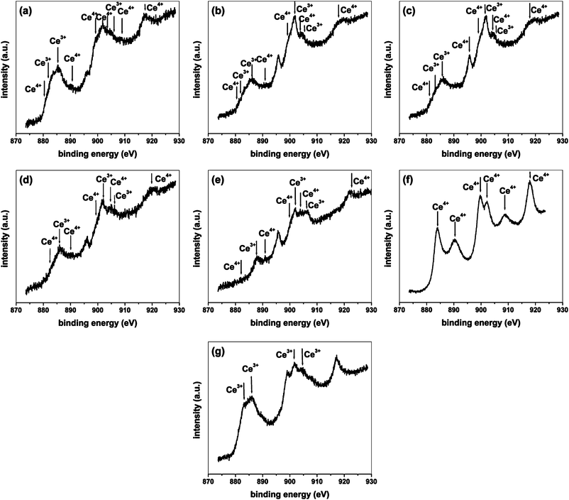 | ||
| Fig. 4 XPS of Ce3d. (a) C-1, (b) C-2, (c) C-3, (d) C-4, (e) C-5, (f) CeO2, (g) CeAlO3. | ||
Mixed Ce3+–Ce4+ oxidation states were observed for rest of the compounds. Peaks characteristic of both +3 as well as +4 states were present, as can be observed form Fig. 4(a–e). Both Ce3+ and Ce4+ states are marked in the figure. In most of the compounds, predominant Ce3+ peaks can be observed. From the XRD of the compounds, the presence of CeAlO3 was confirmed in which Ce was present in the +3 state. Ce in the +4 state was present when the formation of CeO2 took place. The XPS observations are in agreement with the XRD results, conveying the formation of mixed oxides constituting CeO2–Al2O3–CeAlO3 components. In the current study, we have only qualitatively shown the presence of both Ce3+ and Ce4+ states in the compounds. Detailed curve decomposition for obtaining peaks corresponding to Ce3d5/2–3/2 can be accomplished by a careful procedure33 for determining the relative amounts of +3 and +4 states, however, in this study, we have not attempted to quantify the different oxidation states.
It is to be noted that both Ce3+ and Ce4+ states were observed in the compound C-5 also. It was concluded that C-5 mainly consisted of CeO2 from XRD as well as TEM studies. Aluminium in the compound was found to be present in substituted form for Ce4+ sites. This proposition can be rationalized with the help of XPS. Al was substituted in CeO2 in the +3 state. Since the oxidation of Ce in CeO2 is +4, the formation of oxide ion vacancies takes place in the compound for electrostatic neutrality. Therefore, the compound was actually a solid solution of the form Ce1−x4+Alx3+O2−δ where δ is the reduction in oxygen occupancy of the compound due to the substitution of Al in the +3 state. Due to the presence of anionic vacancies in the compound, and the synthesis conditions, there indeed can occur electron transfers and oxygen exchange in the compound leading to a partial reduction of Ce from the Ce4+ to the Ce3+ state as Ce1−x4+Alx3+O2−δ ↔ Ce1−x−y4+Cey3+Alx3+O2−δ′ depending upon the oxygen rich or oxygen lean conditions at high temperatures of synthesis.
CO oxidation activity of hybrid oxides
CO oxidation was carried out over all the synthesized compounds. The variation of CO concentration with temperature over the different compounds is shown in Fig. 5. All the compounds were found to be catalytically active for the conversion of CO to CO2 and more than 90% conversions were observed over most of the compounds within 500 °C. The activity of the compounds, based on the conversions achieved at given temperatures, followed the order C-5 > CeO2 > C-3 > CeAlO3 > C-1 > C-4 ≈ C2. | ||
| Fig. 5 Variation of CO concentration with temperature during CO oxidation reaction over the different compounds. | ||
The variation of the rate of reaction with temperature is shown in Fig. 6. The rates of the reaction are the highest for C-5 followed by CeO2 and the general trend discussed above can also be observed in this figure. The intermediate activity of CeAlO3 compared to the different mixed oxides can be observed in Fig. 6a. Another important observation from Fig. 6a is the sigmoidal nature of temperature dependence of the rate of reaction. In the case of C-5, which showed the highest activity, the exponential increase in the rate of reaction with temperature was observed for a small range of temperature followed by saturation. Similar trends were observed for the other compounds also but at much higher temperatures (not shown in the figure). From the temperature dependence of CO conversion as well as the reaction rate, a clear trend in the activity of the compound was established. The Arrhenius plot showing the variation of natural log of the initial rate of reaction with the inverse of absolute temperature is shown in Fig. 6b. The plot was drawn for only a limited range of temperature as the ordinate in the figure is the initial rate and not the rate constant as in the case of a conventional Arrhenius plot. The linearity in the plot for limited lower conversions can be seen from Fig. 6b. Deviation from linearity (not shown in the figure) was observed which is a typical behavior of heterogeneous reaction and the non-linearity at higher conversions and temperatures is due to a change in the rate control regimes and mass transfer limitations. Therefore, we have concentrated on the linear portion of the plot. The activation energies over the complete range of conversion can be obtained only by a detailed kinetic model and fitting of the rate parameters. The activation energies calculated from Fig. 6b show only a qualitative trend because they are based on the initial rates. However, it is clear that the activation energy is the lowest for C-5 and high for C-2, C-4 and CeAlO3. This plot also establishes the highest activity (and lowest activation energy) of the C-5 compound compared to the other compounds investigated in this study. The reason behind the differences in the activity of different compounds and the order of activity depends upon several factors. We describe each of them by classifying the compounds into mainly three categories.
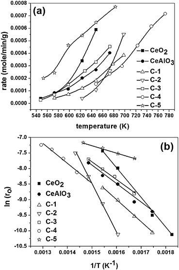 | ||
| Fig. 6 Temperature dependence of the rate of reaction. (a) Variation rate of CO conversion with temperature. (b) Arrhenius plot. | ||
CeO2 shows the activity for CO oxidation owing to the reducibility of the compound. Owing to the oxygen storage capacity of the compound, a small fraction of oxygen atoms in the compound can be exchanged from the stream resulting in the formation of CO2 and reduced CeO2. The oxidation of CeO2 takes place by the stream oxygen. The following steps can be written for the reaction
| CeO2 + δCO → CeO2−δ + δCO2 | (1) |
| CeO2−δ + δ/2O2 → CeO2 | (2) |
The activity of C-5 was found to be higher than the activity of CeO2. In C-5, Al was substituted in CeO2 and this increases the lability of oxygen in the compound and also induces vacancy formation. The enhancement in the reducibility of the compound on ionic substitution has been established using density functional theory calculations for several metal–CeO2 systems.34,35 Further, the anionic vacancies aid oxygen dissociation and, hence, increase the activity of the compound. The mechanism of involvement of anionic vacancies for CO oxidation has been established in our previous study.36 Therefore, with Al substituted in ionic form in CeO2, C-5 shows the highest activity for the reaction. Small crystallite size and higher surface area of C-5 also contributes to this effect. However, at very high temperature, over reduction of the compound may take place owing to smaller crystallite size and higher reducibility. This is detrimental for the activity of the catalyst and as a result, the activity of the compound was found to be lesser than the activity of pure CeO2 above 400 °C.
The activity of CeAlO3 can be explained on the basis of interconversion of the compound to hybrid CeO2–Al2O3 oxides. As mentioned earlier, the active species in the hybrid oxide is CeO2. The surface formation of CeO2–Al2O3 can take place following the reaction given below.
| 2δCeAlO3 + δ/2O2 → (CeO2)2δ(Al2O3)δ | (3) |
| (CeO2)2δ(Al2O3)δ + δCO → 2δCeAlO3 + δCO2 | (4) |
To the best of our knowledge, CO oxidation activity of CeAlO3 has not been reported previously. Prakash et al.37 have studied phase evolution and thermal stability of CeO2/γ-Al2O3 systems. The CeAlO3 phase was observed on thermal treatment and interconversions of CeO2/γ-Al2O3 and CeAlO3/γ-Al2O3 were observed by surface oxidation–reduction steps. Complete transformation from one phase to another phase required temperatures as high as 700 °C. The presence of mixed Ce3+/Ce4+ states in CeAlO3 at lower temperatures showed the surface oxidation of the compound. This is in support of our current observation and the redox processes during CO oxidation over CeAlO3 can be expected to take place via the surface oxidation mechanism shown by eqn (3). CeAlO3 phase formation in CeO2–ZrO2–Al2O3 systems has been reported by Liotta et al.38 The formation of CeAlO3 was found to be detrimental to the catalytic activity of the compound. Ce3+–Ce4+ transformations were observed in their studies also corresponding to the interconversions of CeAlO3 and CeO2. A similar mechanism can be expected over the hybrid oxides that have CeAlO3, CeO2 and Al2O3. One of the parameters governing the activity of the catalyst can be the relative amounts of the three components. C-1, C-2 and C-4 had similar crystallite sizes, surface areas and they also showed similar activity. To summarize, the activity of the compounds for CO oxidation is a result of the relative contributions of the crystallite size, surface area and composition of the hybrid oxide.
Conclusions
CeO2–Al2O3–CeAlO3 hybrid oxides were synthesized using the modified solution combustion technique. A mixture of fuels approach was adopted to obtain sub-10 nanometre crystallites. Pure phases, mixed oxides and solid solutions could be synthesized selectively by tuning the ratio of the fuels in the solution. A solid solution of CeO2 with Al substitution could be obtained using a mixture of glycine, urea, hexamine and oxalyl dihydrazide with 2–3 nm crystallite size. All the compounds showed activity for CO oxidation and the activity of the compound was found to depend on the surface area and the composition of the hybrid oxide.Acknowledgements
PAD gratefully acknowledges Bristol-Myers Squibb for graduate fellowship. GM gratefully acknowledges Department of Science and Technology, India, for the Swarnajayanti fellowship. The authors thank Dr. Nagesh Kini of Thermax India for the Rietveld analysis.References
- M. R. Hoffmann, S. T. Martin, W. Choi and D. W. Bahnemann, Chem. Rev., 1995, 95, 69 CrossRef CAS.
- J.-N. Park, J. Noh, J.-S. Chang and S.-E. Park, Catal. Lett., 2000, 65, 75 CrossRef CAS.
- C. Meephoka, C. Chaisuk, P. Samparnpiboon and P. Praserthdam, Catal. Commun., 2008, 9, 546 CrossRef CAS.
- B. Hvolbaek, T. V. W. Janssens, B. S. Clausen, H. Falsig, C. H. Christensen and J. K. Norskov, Nano Today, 2007, 2, 14 CrossRef.
- P. B. Amama, C. L. Pint, S. M. Kim, L. McJilton, K. G. Eyink, E. A. Stach, R. H. Hauge and B. Mayurama, ACS Nano, 2010, 4, 895 CrossRef CAS.
- N. Yi, R. Si, H. Saltsburg and M. Flytzani-Stephanopoulos, Energy Environ. Sci., 2010, 3, 831 CAS.
- N. Yi, R. Si, H. Saltsburg and M. Flytzani-Stephanopoulos, Appl. Catal., B, 2010, 95, 87 CrossRef CAS.
- R. Si and M. Flytzani-Stephanopoulos, Angew. Chem., Int. Ed., 2008, 47, 2884 CrossRef CAS.
- S. T. Aruna and K. S. Rajam, Mater. Res. Bull., 2004, 39, 157 CrossRef CAS.
- M. S. Hegde, G. Madras and K. C. Patil, Acc. Chem. Res., 2009, 42, 704 CrossRef CAS.
- S. T. Aruna, N. S. Kini and K. S. Rajam, Mater. Res. Bull., 2009, 44, 728 CrossRef CAS.
- H. Gu and M. D. Soucek, Chem. Mater., 2007, 19, 1103 CrossRef CAS.
- W. J. Stark, J. D. Grunwaldt, M. Maciejewski, S. E. Pratsinis and A. Baiker, Chem. Mater., 2005, 17, 3352 CrossRef CAS.
- T. Yuzhakova, V. Rakic, C. Giomon and A. Auroux, Chem. Mater., 2007, 19, 2970 CrossRef CAS.
- M. Kim, T. R. Hinklin and R. M. Laine, Chem. Mater., 2008, 20, 5154 CrossRef CAS.
- R. Di Monte, P. Fornasiero, S. Desinan, J. Kašpar, J. M. Gatica, J. J. Calvino and E. Fonda, Chem. Mater., 2004, 16, 4273 CrossRef CAS.
- R. Di Monte, P. Fornasiero, M. Graziani and J. Kašpar, J. Alloys Compd., 1998, 275, 877 CrossRef.
- R. Di Monte, P. Fornasiero, J. Kašpar and M. Graziani, Stud. Surf. Sci. Catal., 2001, 140, 229 CrossRef CAS.
- V. C. Belessi, T. V. Bakas, C. N. Costa, A. M. Efstathiou and P. J. Pomonis, Appl. Catal., B, 2000, 28, 13 CrossRef CAS.
- V. C. Belessi, C. N. Costa, T. V. Bakas, T. Anastasiadou, P. J. Pomonis and A. M. Efstathiou, Catal. Today, 2000, 59, 347 CrossRef CAS.
- S. T. Aruna, N. S. Kini, S. Shetty and K. S. Rajam, Mater. Chem. Phys., 2010, 119, 485 CrossRef CAS.
- P. A. Deshpande, S. Polisetti and G. Madras, AIChE J., 2011 DOI:10.1002/aic.12636.
- S. Damyanova, C. A. Perez, M. Schmal and J. M. C. Bueno, Appl. Catal., A, 2002, 234, 271 CrossRef CAS.
- J. M. Wu, Mater. Lett., 2001, 48, 324–330 CrossRef CAS.
- A. Ishihara, H. Negura, T. Hashimoto and H. Nasu, Appl. Catal., A, 2010, 388, 68–76 CrossRef CAS.
- S. K. Lee, S. Y. Park, Y. S. Yi and J. Moon, J. Phys. Chem. C, 2010, 114, 13890 CAS.
- S. Rossignol, F. Gerard and D. Duprez, J. Mater. Chem., 1999, 9, 1615 RSC.
- C. Liang, Z. Ma, H. Lin, L. Ding, J. Qiu, W. Fradensen and D. Su, J. Mater. Chem., 2009, 19, 1417 RSC.
- S. Song, R. O. Fuentes and R. T. Baker, J. Mater. Chem., 2010, 20, 9760 RSC.
- P. A. Deshpande, M. S. Hegde and G. Madras, Appl. Catal., B, 2010, 96, 83 CrossRef CAS.
- S. Sharma, P. A. Deshpande, M. S. Hegde and G. Madras, Ind. Eng. Chem. Res., 2009, 48, 6535 CrossRef CAS.
- T. Baidya, A. Gupta, P. A. Deshpande, G. Madras and M. S. Hegde, J. Phys. Chem. C, 2009, 113, 4059 CAS.
- E. Paparazzo, Chem. Eng. J., 2011, 170, 342–343 CrossRef CAS.
- T. Baidya, G. Dutta, M. S. Hegde and U. V. Waghmare, Dalton Trans., 2009, 455–464 RSC.
- G. Dutta, U. V. Waghmare, T. Baidya, M. S. Hegde, K. R. Priolkar and P. R. Sarode, Catal. Lett., 2006, 108, 165–172 CrossRef CAS.
- S. Roy, A. Marimuthu, M. S. Hegde and G. Madras, Appl. Catal., B, 2007, 71, 23 CrossRef CAS.
- A. S. Prakash, C. Shivakumara and M. S. Hegde, Mater. Sci. Eng., B, 2007, 139, 55–61 CrossRef CAS.
- L. F. Liotta, A. Longo, G. Pantaleo, G. Di Carlo, A. Martorana, S. Cimino, G. Russo and G. Deganello, Appl. Catal., B, 2009, 90, 470–477 CrossRef CAS.
| This journal is © The Royal Society of Chemistry 2011 |