Fabrication of a TiO2 nanoparticles impregnated titanium mesh filter and its application for environmental purification†
Tsuyoshi
Ochiai
*ab,
Toru
Hoshi
ac,
Houda
Slimen
ad,
Kazuya
Nakata
ab,
Taketoshi
Murakami
a,
Hiro
Tatejima
e,
Yoshihiro
Koide
c,
Ammar
Houas
d,
Takuji
Horie
f,
Yuko
Morito
be and
Akira
Fujishima
ab
aKanagawa Academy of Science and Technology, KSP East 421, 3-2-1 Sakado, Takatsu-ku, Kawasaki, Kanagawa 213-0012, Japan. E-mail: pg-ochiai@newkast.or.jp; Fax: +81-44-819-2070; Tel: +81-44-819-2040
bDivision of Photocatalyst for Energy and Environment, Research Institute for Science and Technology, Tokyo University of Science, 1-3 Kagurazaka, Shinjuku-ku, Tokyo 162-8601, Japan
cDepartment of Material and Life Chemistry, Faculty of Engineering, Kanagawa University, 3-27-1 Rokkakubashi, Yokohama, Kanagawa 221-8686, Japan
dEquipe de Catalyse et Environnement, URECAP ENIG/Faculté des Sciences de Gabès, Université de Gabès, Campus Universitaire, 6072 Gabès, Tunisie
eU-VIX Corporation, 2-14-8 Midorigaoka, Meguro-ku, Tokyo 152-0034, Japan
fHORIE Corporation, 5090 Kamidori, Tsubame, N, iigata 959-1276, Japan
First published on 6th July 2011
Abstract
A novel photocatalytic filter, titanium-mesh sheet modified with TiO2 (TMiP), was fabricated and applied for environmental purification. The high flexibility of TMiP allows for an easy to design and fabricate photocatalytic reactor. Moreover, TMiP provides an excellent air or water pass-through while maintaining a high level of surface contact with UV irradiation.
Environmental purification is one of the most important technologies for human life. Application of the strong oxidation ability of TiO2 for environmental purification has received growing attention.1–3 Various photocatalytic filter materials and environmental purifiers are available now. However, there are some problems such as limitation of decomposition efficiency and difficulty in handling the filter materials. Therefore, the market for photocatalytic environmental purifiers does not have a large share such as that of exterior materials. Here we report the easy-to-handle photocatalytic filter material, TiO2 nanoparticles impregnated titanium mesh (TMiP), and its ability for air- and water-purification.
The fabrication method of TMiP is shown in Fig. 1. In the first step, both sides of a titanium sheet (A4 size, 0.2 mmt) were coated by different patterns of resist. Then the titanium sheet with resist patterns was immersed in acid solution and was converted to Ti-mesh by chemical etching according to resist patterns. The obtained highly-ordered three dimensional Ti-mesh structure could be controlled by design of resist pattern and etching time. After etching, the Ti-mesh was anodized at a voltage of 70 V in aqueous solution containing phosphoric acid (3%) and was heated at 550 °C for 3 h to prepare the titanium dioxide layer on its surface. In this step, the Ti-mesh showed violet color by the interference with the thickness of the titanium dioxide layer. The interference colors could be controlled by varying the thickness of the titanium dioxide layer with various anodizing voltages and times. Finally, the anodized Ti-mesh was dip-coated in 25 wt% TiO2 anatase sol (TKD-701, TAYCA) at a 0.5 mm s−1 withdrawal speed and was heated at 550 °C for 3 h to sinter TiO2 nanoparticles onto the anodized Ti-mesh surface. For comparison, the commercial Ti-mesh (200 × 200 mm, 0.30 mm ϕ, 20 mesh, Nilaco) was coated by TiO2 and was evaluated by the same method.
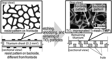 | ||
| Fig. 1 Schematic illustrations for fablication of TMiP. | ||
The surface morphology of TMiP was examined by scanning electron microscopy (SEM; JSM-5400 microscope, JEOL). The crystalline structure of TiO2 on TMiP was investigated by X-ray diffractometry (XRD; RINT 1500, Rigaku). The SEM images of the TMiP are shown in Fig. 2a and b. On the other hand, the SEM image of the Ti-mesh before sintering TiO2 is shown in ESI†, Fig. S1a. These images indicate that the TiO2 films were made up of spherical particles on the TMiP by sintering, and the particle sizes of TiO2 in the films were about 0.1 μm. This is larger than the particle size in suspension. In the sol–gel coating method for immobilization of TiO2, repeated calcination treatment of the TiO2 films results in the growth and aggregation of the particles.4 Thus, a similar process is likely to be occurring in the present procedure. Interestingly, the SEM images of TiO2 sintered commercial Ti-mesh did not show such spherical particles of TiO2 on the surface (Fig. 2c and d). These results may be because of the difference in the surface structures of the chemically etched Ti-mesh and the commercial Ti-mesh. The XRD patterns of the Ti-mesh, anodized-heated Ti-mesh, and the TMiP are shown in Fig. 3. The XRD patterns of the Ti-mesh and anodized-heated Ti-mesh show only the titanium peak (Fig. 3a and b). On the other hand, the XRD pattern of TMiP shows the dominance of the anatase phase and the appearance of traces of the rutile phase (Fig. 3c). This indicates that the Ti-mesh surface was successfully modified with anatase TiO2 nanoparticles, as reported in the sol–gel coating method.4
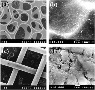 | ||
Fig. 2
SEM images of TMiP and TiO2 coated commercial titanium mesh. (a) TMiP ×35, (b) TMiP ×10![[thin space (1/6-em)]](https://www.rsc.org/images/entities/char_2009.gif) 000, (c) TiO2 coated commercial titanium mesh ×35 and (d) TiO2 coated commercial titanium mesh ×10000. 000, (c) TiO2 coated commercial titanium mesh ×35 and (d) TiO2 coated commercial titanium mesh ×10000. | ||
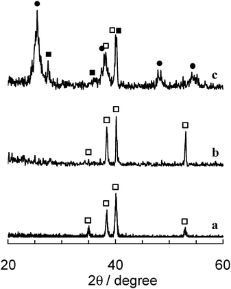 | ||
| Fig. 3 XRD patterns of (a) Ti foil, (b) anodized and heated Ti-mesh, and (c) TMiP (filled circles: anatase TiO2; filled squares: rutile TiO2; open squares: Ti). | ||
The air-purification ability of TMiP was evaluated by an acetaldehyde decomposition test. A schematic diagram of the total experimental system is shown in Fig. 4. The photocatalyst unit consisted of a UV-C lamp (TOSHIBA GL10, 10 W, 10 mW cm−2 at 254 nm) with rolled TMiP or TiO2 sintered commercial Ti-mesh and a fan was placed inside the test room (acryl sealed 1 m3 box). Air was blown onto the TiO2 surface continuously, and 0.3 L of 1% acetaldehyde gas balanced with nitrogen (Sumitomo Seika) was injected from the injection port. The time course of the concentration of acetaldehyde was monitored by a Photoacoustic Infra Red Multigas Monitor (AirTech Instruments, INNOVA 1412). The absolute optical power of the UV light (254 nm) was measured by using a UV power meter (Hamamatsu Photonics, C9536/H9535-254). The experiments were carried out at room temperature and atmospheric pressure.
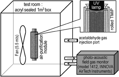 | ||
| Fig. 4 Schematic illustration of an acetaldehyde decomposition test. | ||
Fig. 5 shows the removal of acetaldehyde by the UV-illuminated TMiP (solid line) and compares with results obtained using the TiO2 sintered commercial Ti-mesh (dashed line). It can be seen that acetaldehyde gas can be completely degraded using TMiP catalysts within 2 h while the TiO2 sintered commercial Ti-mesh takes more than 2 h. The acetaldehyde concentrations are well fitted with a pseudo-first-order kinetics given by the equation C = Coexp(−k1t), where Co is the initial acetaldehyde concentration and k1 is the observed rate constant. The values of k1 were calculated by exponential fitting of Fig. 5 to be 2.54 and 0.98 h−1 for TMiP and TiO2 sintered commercial Ti-mesh, respectively. It is clear that the observed rate constant was 2.5 times higher in the case of TMiP than in the case of TiO2 sintered commercial Ti-mesh. We ascribed the results to the good morphology of TMiP and the crystalline structure of TiO2 particles. The highly ordered structure with the interconnected macropores allowed the free exchange and the easy flow-through of acetaldehyde molecules. The porous surface of TMiP provides a well dispersed TiO2 particles for decompose acetaldehyde molecules. One of the evidence for this reason is the BET surface area of TMiP and TiO2 sintered commercial Ti-mesh measured by Gemini V BET surface area analyzer (Micromeretics). The specific surface area of TMiP is 38.12 m2 g−1. On the other hand, the TMiP before sintering TiO2 (anodized and heated Ti-mesh) and the TiO2 sintered commercial Ti-mesh have too small surface area to measure. Moreover, the anatase titania has been reported to be more photocatalytically active than the rutile form because the adsorption affinity of organic molecule towards the anatase phase is larger compared to that towards the rutile.5 On the other hand, water-purification ability of TMiP was evaluated by a methylene blue (MB) decolorization test.6Fig. 6 shows the schematic illustrations of water-purification units which consist of a TMiP, a UV lamp, a pump, and an air bubbler. For comparison of the effects of structure, flow, and air bubbling, five types of units were investigated: (a) plate-type, (b) tube-type, (c) tube-type/flow, (d) tube-type/air, and (e) tube-type/flow/air. The reactor was a plastic vat for (a) or an acrylic tube with 1 L of total volume for (b)–(e). The acrylic tube was equipped with two ports for water flow inlet and outlet. The irradiation was provided by a UV lamp (FL10BLB, Toshiba) on the vat for (a) or in the tube for (b)–(e). The TMiP catalyst (279 mm × 215 mm) was used, being fixed in the bottom of the vat for (a) or around the UV lamp for (b)–(e). One litre of an aqueous solution containing 40 μM MB was supplied to the units and was treated under each condition. For (c) and (e), the solution was circulated through the units by a pump at a flow rate of 100 mL min−1. The concentration of dissolved MB as a function of irradiation time was measured with a UV–visible spectrophotometer (2450, Shimadzu).
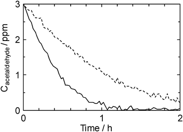 | ||
| Fig. 5 Time course of acetaldehyde concentration in the test room (dashed line: TiO2 sintered commercial Ti-mesh; solid line: TMiP). | ||
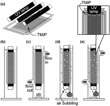 | ||
| Fig. 6 Schematic illustrations of water-purification units. (a) plate-type, (b) tube-type, (c) tube-type/flow, (d) tube-type/air, (e) tube-type/flow/air. | ||
MB decolorization by each unit is shown in Fig. 7. The pseudo-first order rate constants for decolorization, k1, are summarized in Table 1. In all cases, photolysis in the presence of a TMiP resulted in net MB decolorization. Photolysis by the tube-type unit in the absence of a TMiP produced negligible MB decolorization (blank). Similarly, under dark conditions, MB decolorization by the units has not been achieved. Thus, the results of decolorization were due to a photocatalytic activity. There is almost no difference in the rate constants among plate-type (Fig. 6a), tube-type (Fig. 6b), and tube-type/air (Fig. 6d). However, it was observed that circulation of solution by a pump did improve the rate constant (tube-type/flow). The k1 of MB decolorization increased by a factor of 1.7 compared to that for the tube-type without flow. This result indicates that fluid dynamics in the reactor is critical for optimization of the photocatalysis efficiency.7 Interestingly, tube-type/flow/air (Fig. 6e) showed the highest decolorization rate. Tasbihi et al. reported that the dissolved oxygen could improve the efficiency of the degradation of organics by enhancing the separation of photogenerated electron–hole pairs, thereby increasing the ˙OH concentration.8 Thus, the fluid dynamics in the reactor and air bubbling resulted in the highest decolorization rate together with excellent accessibility of the TMiP structure in the present research.
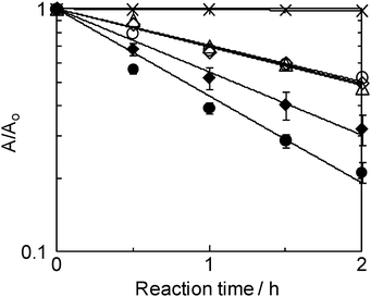 | ||
| Fig. 7 Time cource of decolorization by the units. Crosses: blank experiment; open triangles: plate-type (Fig. 6a); open diamonds: tube-type (Fig. 6b); solid diamonds: tube-type/flow (Fig. 6c); open circles: tube-type/air (Fig. 6d); solid circles: tube-type/flow/air (Fig. 6e). | ||
In conclusion, high efficiency resulted from the highly-ordered three dimensional structure of TMiP. It is clearly shown that high flexibility and accessibility of TMiP allows for an easy to design and fabricate photocatalytic reactor for environmental purification. Moreover, the purification efficiency of TMiP did not decrease by repeating the test. This result indicates the strong adhesion of TiO2 nanoparticles onto the TMiP surface. Although we used simple reactors with conventional conditions, it would be attractive to develop a similar environmental purifier for the practical use.
Notes and references
- A. Fujishima and K. Honda, Nature, 1972, 238, 37 CrossRef CAS.
- A. Fujishima, T. N. Rao and D. A. Tryk, J. Photochem. Photobiol., C, 2000, 1, 1 CrossRef CAS.
- A. Fujishima, X. Zhang and D. A. Tryk, Surf. Sci. Rep., 2008, 63, 515 CrossRef CAS.
- H. Hu, W. Xiao, J. Yuan, J. Shi, M. Chen and G. W. Shang, J. Environ. Sci., 2007, 19, 80 CrossRef CAS.
- P. Periyat, K. V. Baiju, P. Mukundan, P. K. Pillai and K. G. K. Warrier, Appl. Catal., A, 2008, 349, 13 CrossRef CAS.
- T. Ochiai, T. Fukuda, K. Nakata, T. Murakami, D. Tryk, Y. Koide and A. Fujishima, J. Appl. Electrochem., 2010, 40, 1737 CrossRef CAS.
- V. A. Dzhupanov and E. S. Manoach, SMiRT-9 Conference-Programs, Lausanne, Switzerland, 1987.
- M. Tasbihi, C. R. Ngah, N. Aziz, A. Mansor, A. Z. Abdullah, L. K. Teong and A. R. Mohamed, Ind. Eng. Chem. Res., 2007, 46, 9006 CrossRef CAS.
Footnote |
| † Electronic supplementary information (ESI) available: SEM images of TMiP before and after sintering of TiO2. See DOI: 10.1039/c1cy00185j |
| This journal is © The Royal Society of Chemistry 2011 |