Morphology effects of Co3O4 nanocrystals catalyzing CO oxidation in a dry reactant gas stream†
Yonghong
Teng
*a,
Yoshihiro
Kusano
b,
Masaki
Azuma‡
a,
Masatake
Haruta
c and
Yuichi
Shimakawa
a
aInstitute for Chemical Research, Kyoto University, Uji 611-0011, Japan. E-mail: teng@msk.kuicr.kyoto-u.ac.jp; Fax: +81 774-38-3118; Tel: +81 774-38-3115
bCollege of the Arts, Kurashiki University of Science and the Arts, 2640 Nishinoura, Tsurajima-cho, Kurashiki-shi, Okayama 712-8505, Japan
cDepartment of Applied Chemistry, Graduate School of Urban Environmental Sciences, Tokyo Metropolitan University, 1-1 Minami-osawa, Hachioji 192-0397, Tokyo, Japan
First published on 14th June 2011
Abstract
Nanocrystals of Co3O4 having different shapes (plates, rods, cubes, and spheres) were synthesized by using a hydrothermal method and their catalytic activities for CO oxidation were measured in dry reactant gas. The plate-like NCs mainly exposing {111} planes showed the highest catalytic activity among the four kinds of NCs.
Nano-sized materials that we call nanocrystals (NCs) have attracted interest because their properties differ from those of bulk crystals,1–4 and such properties have been found to depend on the shape as well as the size of the NCs.5–11
Co3O4 NCs exhibit catalytic activity so high that they could possibly replace noble metal catalysts. Their catalytic activity in CO oxidation has been recently reported to strongly depend on the NC morphology.12,13Co3O4 nanorods, for example, show much higher catalytic activity than do conventional nanoparticles of this material.12
In the present study we further investigated the effects of morphology on catalytic activity by using a hydrothermal method to synthesize Co3O4 NCs having different shapes—plate-like (P-Co3O4), rod-like (R-Co3O4), cubical (C-Co3O4), and roughly spherical (S-Co3O4)—and comparing their catalytic activities in CO oxidation. Synthesis conditions were changed as little as possible in order to minimize the influence of surface defects and impurities on catalytic properties.14–18 In the catalytic activity measurements special care was taken to supply dry reactant gas in order to decrease the influence of the several ppm H2O vapor usually present in reactant feed gas,19–21 and H2O adsorbed on the surface of Co3O4 NCs21–24 was removed by pre-treatment at 573 K.
X-Ray diffraction (XRD) patterns for the four kinds of samples prepared are shown in ESI†, Fig. S1. All the patterns obtained could be indexed with the spinel structure of Co3O4 without any unidentified peaks. We thus conclude that the samples were Co3O4 NCs.
TEM images of the four kinds of samples are shown in Fig. 1 along with selected-area electron diffraction (SAED) patterns and illustrations. Fig. 1(a1–a3) shows results for P-Co3O4 NCs with an average length (edge to edge) of 80 nm and an average thickness of 8 nm. Some cracks and interspaces in the plate can be seen and most of the plate-shaped sample consists of small crystals with sizes from 10 to 17 nm. Electron diffraction (ED) results revealed that each plate exposes the {111} plane. Fig. 1(b1–b3) shows results for R-Co3O4 NCs with a mean diameter of 13 nm and lengths ranging from several nanometres to 100 nm (average length = 40 nm). The rods consist of bead-like small NCs. Strong ED intensity from the (110) of Co3O4 with weak diffraction spots was observed, suggesting that the rod-like NCs were mainly formed by the {110} facets. Fig. 1(c1–c3) shows results for C-Co3O4 NCs having 30 nm edges and partly round corners. Its exposed plane is the (100) plane. Fig. 1(d1–d3) shows results for S-Co3O4 NCs. Although their morphologies were not well defined, most of the NCs were roughly spherical and had an average diameter 42 nm. Many facets can be confirmed by the ED patterns.
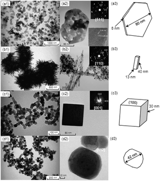 | ||
| Fig. 1 TEM images, selected-area electron diffraction (SAED) patterns, and illustrations for Co3O4 NCs with different shapes: (a1)–(a3), plate; (b1)–(b3), rod; (c1)–(c3), cube; (d1)–(d3), sphere. | ||
As summarized in Table 1, the sizes of the NCs estimated from diffraction peak widths in the XRD patterns were 11 nm for P-Co3O4 NCs, 17 nm for R-Co3O4 NCs, 31 nm for C-Co3O4NCs, and 29 nm for S-Co3O4 NCs. These estimated sizes are fairly consistent with the sizes seen in the TEM observations. The specific surface areas obtained by BET measurements for the corresponding samples were, respectively, 53, 62, 36, and 30 m2 g−1. Note that the specific surface area of R-Co3O4 NCs is larger than that of P-Co3O4 NCs.
| Shape | Average size by TEM/nm | Crystalline size by XRD/nm | Specific surface area/m2 g−1 | Predominant plane | E a/kJ mol−1 | A/molecule m−2s−1 | Reaction rate at 200 K/10−2 μmol CO m−2s−1 |
|---|---|---|---|---|---|---|---|
| Plate | 8 (thickness) | 11 | 53 | {111} | 21 | 1.3 × 10²² | 9.5 |
| 80 (contour) | |||||||
| Rod | 13 (diameter) | 17 | 62 | {110} | 40 | 1.1 × 1026 | 0.8 |
| 40 (length) | |||||||
| Cube | 30 (edge) | 31 | 36 | {100} | 33 | 1.9 × 1024 | 0.7 |
| Sphere | 42 (diameter) | 29 | 30 | Multi planes | 27 | 6.3 × 10²² | 0.7 |
Fig. 2 shows light-off curves of CO oxidation obtained for the four kinds of Co3O4 NCs. All samples had the same surface area (3.6 m2) but their masses differed. The oxidation of CO occurs at temperatures below 273 K, and the T50 (reaction temperature at 50% conversion) values for P-, R-, C- and S-Co3O4 NCs were, respectively, 190, 218, 225, and 230 K (Table 1). These values are much lower than those reported in a normal gas stream (T50 > 323 K). The lowest T50 among those of the four kinds of samples was that for P-Co3O4, and that value was much lower than the value reported for Co3O4 NCs (S = 52.1 m2 g−1, SV = 20![[thin space (1/6-em)]](https://www.rsc.org/images/entities/char_2009.gif) 000 h−1 ml g−1cat) in a dry gas stream (T50 = 219 K).19 It was also confirmed that the sample morphologies of the present Co3O4 NCs were the same after the catalytic measurements.
000 h−1 ml g−1cat) in a dry gas stream (T50 = 219 K).19 It was also confirmed that the sample morphologies of the present Co3O4 NCs were the same after the catalytic measurements.
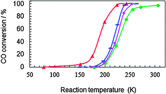 | ||
Fig. 2 Conversion as a function of reaction temperature for CO oxidation over differently shaped Co3O4 NCs: (▲) plate, (![[thick line, graph caption]](https://www.rsc.org/images/entities/char_e117.gif) ) rod, (■) cube, (●) sphere. The amount of each sample corresponded to a surface area of 3.6 m2: 68 mg for P-Co3O4 NCs, 58 mg for R-Co3O4 NCs, 100 mg for C-Co3O4 NCs, and 120 mg for S-Co3O4 NCs. The stream consisted of 1.0 vol% CO and 21 vol% O2 in He, and the gas flow rate was 50 ml min−1. Hourly space velocities for P-, R-, and S-Co3O4 NCs were, respectively, 4.4, 5.2, 3.0, and 2.5 × 10⁴ h−1 ml g−1cat. ) rod, (■) cube, (●) sphere. The amount of each sample corresponded to a surface area of 3.6 m2: 68 mg for P-Co3O4 NCs, 58 mg for R-Co3O4 NCs, 100 mg for C-Co3O4 NCs, and 120 mg for S-Co3O4 NCs. The stream consisted of 1.0 vol% CO and 21 vol% O2 in He, and the gas flow rate was 50 ml min−1. Hourly space velocities for P-, R-, and S-Co3O4 NCs were, respectively, 4.4, 5.2, 3.0, and 2.5 × 10⁴ h−1 ml g−1cat. | ||
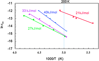
Fig. 3 shows the results of Arrhenius plots for CO oxidation over the Co3O4 NCs. The apparent activation energies (Ea) obtained from the plots are also listed in Table 1. The Ea for P-, R-, C-, and S-Co3O4 NCs were, respectively, 21, 40, 33, and 27 kJ mol−1, all of which were much lower than the reported Ea in a normal reactant gas stream containing more than 1 ppm H2O (50–54 kJ mol−1).16P-Co3O4 had the lowest Ea among the four. The Ea of S-Co3O4 NCs (27 kJ mol−1) is similar to that of usual Co3O4 NCs with a smaller diameter (11 nm).16R-Co3O4 NCs had the highest Ea values. The different Ea values show that reaction pathways differ somewhat depending on the morphology in dry gas stream. Reaction rates per unit specific surface area at 200 K were, respectively, 9.5, 0.8, 0.7, and 0.7 × 10⁻² μmol m−2s−1, for P-, R-, C-, and S-Co3O4 NCs (Table 1). Note that the value for P-Co3O4 NCs is an order of magnitude higher than the values for R-, C-, and S-Co3O4 NCs.
 | ||
| Fig. 3 Arrhenius plots for the rate of CO oxidation over differently shaped Co3O4 NCs: (▲) plate, () rod, (■) cube, (●) sphere. Apparent activation energy (Ea) is shown for each catalyst. The stream consisted of 1.0 vol% CO and 21 vol% O2 in He, and the gas hourly space velocity was changed in the range of 3.0 × 10⁴ to 2.4 × 10⁵ h−1 ml g−1cat in order to obtain CO conversion below 15% for differential reactor assumption. | ||
It was reported that for CO oxidation under a normal gas stream containing more than 3 ppm H2O the catalytic activity of the {110} crystal planes of Co3O4 NCs was higher than that of either the {100} or {111} planes.12 Indeed, rod-shaped Co3O4 NCs, which mainly consisted of {110} exposed planes, showed high catalytic activity at around 200 K.12 On the other hand, calculation results showed that {100} planes are more stable than {111} and {110} planes that expose the active sites of Co3+ in Co3O4 NCs.25–27 Moreover, {111} planes expose a stable outmost surface after relaxation, while surface relaxation of the {110} plane is not significant.26,27 In our study the catalytic activities were measured under dry stream, which is closer to the ideal condition assumed in computational calculation. We then suppose that {111} planes may keep their active surfaces in dry reactant gas to give a high catalytic activity. In addition, our R-Co3O4 NCs exposed {110} planes together with other crystal planes to lower their catalytic activity. These lead to a total result that our P-Co3O4 NCs showed the highest catalytic activity. The stability of surface and/or surface energy is related to catalytic activity, for example, the surface energy of anhydrous Co3O4 NCs has been reported to be twice that of hydrated Co3O4 NCs,28 which is consistent with the difference of catalytic activity between anhydrous and hydrated Co3O4 NCs.19
In summary, Co3O4 NCs having different shapes—plate-like, rod-like, cubical, and roughly spherical—were synthesized in aqueous solution by a hydrothermal reaction. Plate-like Co3O4 NCs mainly exposing {111} planes exhibited the highest catalytic activity for CO oxidation: T50 = 190 K and Ea = 21 kJ mol−1. At 200 K their catalytic activity was an order of magnitude higher than that of the other NCs.
This work was partly supported by a Grant-in-Aid for Scientific Research (19GS0207) and by the Joint Project of Chemical Synthesis Core Research Institutions from the Japanese Ministry of Education, Culture, Sports, Science and Technology.
Notes and references
- C. Burda, Z. Chen, R. Narayanan and M. A. El-sayed, Chem. Rev., 2005, 105, 1025–1102 CrossRef CAS.
- S. Laurent, D. Forge, M. Port, A. Roch, C. Robic, L. V. Elst and R. N. Muller, Chem. Rev., 2008, 108, 2064–2110 CrossRef CAS.
- M. Auffan, J. Rose, J.-Y. Bottero, G. V. Lowry, J.-P. Jolovet and M. R. Wiesner, Nat. Nanotechnol., 2009, 4, 634–641 CrossRef CAS.
- M. Haruta, Chem. Rec., 2003, 3, 75–87 CrossRef.
- N. Semagina and L. Kiwi-Minsker, Catal. Rev., 2009, 51, 147–217 CrossRef CAS.
- G. A. Somorjai and J. Y. Park, Top. Catal., 2008, 49, 126–135 CrossRef CAS.
- J. C. Volta and J. L. Portefaix, Appl. Catal., 1985, 18, 1–32 Search PubMed.
- J. E. Germain, in Adsorption and Catalysis on Oxide Surfaces, ed. M. Che and G. C. Bond, Elsevier Sci. Pub., 1985, pp. 355–370 Search PubMed.
- A. Miyamoto, K. Mori, M. Miura and Y. Murakami, in Adsorption and Catalysis on Oxide Surfaces, ed. M. Che and G. C. Bond, Elsevier Sci. Pub., 1985, pp. 371–380 Search PubMed.
- J. Haber, in Structure and Reactivity of Surfaces, ed. C. Morterra, A. Zecchina and G. Gosta, Elsevier Sci. Pub., 1989, pp. 447–467 Search PubMed.
- K. Zhou, X. Wang, X. Sun, Q. Peng and Y. Li, J. Catal., 2005, 229, 206–212 CrossRef CAS.
- X. Xie, Y. Li, Z.-Q. Liu, M. Haruta and W. Shen, Nature, 2009, 458, 746–749 CrossRef CAS.
- L. Hu, K. Sun, Q. Peng, B. Xu and Y. Li, Nano Res., 2010, 3, 363–368 Search PubMed.
- M. Casas-Cabanas, G. Binotto, D. Larcher, A. Lecup, V. Giordani and J.-M. Tarascon, Chem. Mater., 2009, 21, 1939–1947 CrossRef CAS.
- V. A. Sadykov, S. F. Tikhov, S. V. Tsybulya, G. N. Kryukova, S. A. Veniaminov, V. N. Kolomiichuk, N. N. Bulgakov, E. A. Paukshtis, V. P. Ivanov, S. V. Koshcheev, V. I. Zaikovskii, L. A. Isupova and L. B. Burgina, J. Mol. Catal. A: Chem., 2000, 158, 361–365 CrossRef CAS.
- Y. Yu, T. Takei, H. Ohashi, H. He, X. Zhang and M. Haruta, J. Catal., 2009, 267, 121–129 CrossRef CAS.
- L. Simonot, F. Garin and G. Maire, Appl. Catal., B, 1997, 11, 167–179 Search PubMed.
- N. R. E. Radwan, M. Mokhtar and G. A. El-shobaky, Appl. Catal., A, 2003, 241, 77–90 Search PubMed.
- D. A. H. Cunningham, T. Kobayashi, N. Kamijo and M. Haruta, Catal. Lett., 1994, 25, 257–264 CrossRef CAS.
- Y. Takita, T. Tashiro, Y. Saito and F. Hori, J. Catal., 1985, 97, 25–35 Search PubMed.
- F. Grillo, M. M. Natile and A. Glisenti, Appl. Catal., B, 2004, 48, 267–274 CrossRef CAS.
- Y.-Z. Wang, Y.-X. Zhaim, C.-G. Gao and D.-S. Liu, Catal. Lett., 2007, 116, 136–142 CrossRef CAS.
- R. Xu and H.-C. Zeng, J. Phys. Chem. B, 2003, 107, 12643–12649 CrossRef CAS.
- Y. Teng, S. Yamamoto, H. Kusano, M. Azuma and Y. Shimakawa, Mater. Lett., 2010, 64, 239–242 Search PubMed.
- W. Ever and H. H. Kung, Philos. Mag. B, 1985, 52, 1135–1145 Search PubMed.
- P. Broqvist, I. Panas and H. Persson, J. Catal., 2002, 210, 198–206 CrossRef CAS.
- X.-L. Xu, Z.-H. Chen, Y. Li, W.-K. Chen and J.-Q. Li, Surf. Sci., 2009, 603, 653–658 CrossRef CAS.
- A. Navrotsky, C. Ma, K. Lilova and N. Birkner, Science, 2010, 330, 199–201 CrossRef CAS.
Footnotes |
| † Electronic supplementary information (ESI) available: Experimental details. See DOI: 10.1039/c1cy00113b |
| ‡ Current address: Materials and Structures Laboratory, Tokyo Institute of Technology, 4259 Nagatsuta, Yokohama 226-8503, Japan. |
| This journal is © The Royal Society of Chemistry 2011 |