Bifunctional composite prepared using layer-by-layer assembly of polyelectrolyte–gold nanoparticle films on Fe3O4–silica core–shell microspheres†
Hongfang
Li
,
Shuiying
Gao
,
Zhaoliang
Zheng
and
Rong
Cao
*
State Key Laboratory of Structural Chemistry, Fujian Institute of Research on the Structure of Matter, Chinese Academy of Sciences, Fujian, Fuzhou, 350002, P. R. China. E-mail: rcao@fjirsm.ac.cn; Fax: +86 591 83796710; Tel: +86 591 83796710
First published on 12th August 2011
Abstract
Layer-by-layer assembly of polyelectrolyte–gold nanoparticles (NPs) multilayer films on Fe3O4–silica core–shell microspheres provides a convenient method to design a bifunctional hybrid composite combining the catalytic and magnetic performance together. The Au NPs are effectively immobilized in the polyelectrolyte layer without blocking the catalytic sites. The obtained hybrid magnetic microspheres exhibit high catalytic performance in both organic and inorganic reduction reactions. The use of magnetic support for the immobilization of Au NPs guarantees facile, clean, fast and efficient separation of the catalyst at the end of the reaction cycle.
Introduction
With the rapid progress of nanoscience and nanotechnology, the combination of different nanomaterials to afford multifunctional integrated composite nanomaterials becomes possible.1 Such multifunctional nanomaterials are significantly fascinating because of their potential applications in biomedicine, optical devises, and catalysis field.2 Recently, intensive work has been done to design unique nanostructures for composite nanomaterials and to achieve the combination of properties of each component or cooperatively enhanced performances.3 Especially, core–shell structured nanocomposites have gained much more interest due to their improved properties when compared to other structures.4Although noble metallic NPs are attractive for catalysis because of their large surface area-to-volume ratio,5 aggregation often accrues among them, which will greatly reduce the catalytic activity and selectivity.6 To overcome this problem, the catalytic NPs are usually immobilized on various solid supports such as carbon, metal oxides, and zeolites.7 However, as the size of the support decreases, separation using physical methods, such as filtration or centrifugation, becomes difficult and time-consuming. Magnetic separation can be considered an effective and environmentally benign separation approach, since it minimizes the use of auxiliary substances and energy for achieving catalyst recovery.8 To improve the thermal and chemical stability, solubility and biocompatibility of the support, the Fe3O4 magnetic particles were usually coated with a SiO2 shell to form a core–shell Fe3O4@SiO2 structure. Many methods have been explored to immobilize noble metal NPs on Fe3O4@SiO2 magnetic support. The most widely used method is directly planting –NH2 or –SH groups on the silica shell, which acted as anchor to coordinate with ionic or metallic NPs.9 This protocol is facile to conduct, but it is hard to control the size and morphology of the metal NPs. The other method is to grow organic functional networks such as PAMAM dendrimers on the surface of silica to stabilize metal NPs.10 Although the organic networks exhibit many advantages, the tedious operation steps and long synthetic period do not meet the large-scale application.
The LbL assembly has been developed into a general and efficient approach used in a variety of application fields.11 It was originally based on alternate adsorption of oppositely charged polyelectrolytes on solid surfaces from their solutions. Lee et al. firstly reported the assembly of PAA and PEI-Pd(II) multilayer films on magnetic particles.12 However, only 2/3 of the Pd(II) ions were reduced to metallic Pd NPs, and the loading amount of Pd NPs is relatively small. To overcome such shortcomings, we improved the LbL technique using pre-synthesized Au NPs as metal source instead of ionic metal. The Au NPs with controlled size and shape were synthesized and negatively charged in advance. Then the positive PEI polyelectrolyte and the negative Au NPs were consecutively deposited onto the Fe3O4@SiO2 microspheres to construct a magnetic and catalytic bifunctional composite. The formation of Au NPs prior to their immobilization allows for control over the particle size and shape to yield remarkably active catalyst. Moreover, the loading amount of the noble metal NPs can be readily controlled through adjusting the number of PEI–Au bilayers.
Experimental
Synthesis of silica-coated magnetic microspheres
The Fe3O4 magnetic particles were prepared through a hydrothermal reaction according to the literature.13 Briefly, 2.70 g of FeCl3·6H2O and 7.20 g of sodium acetate were dissolved in 100 mL of ethylene glycol under magnetic stirring. The obtained homogeneous yellow solution was transferred to an autoclave and heated at 200 °C for 8 h. The as-prepared Fe3O4 particles were washed with ethanol several times and dried in vacuum. The core–shell Fe3O4@SiO2 microspheres were prepared through a versatile sol–gel method as follows:14 0.1 g of Fe3O4 particles were treated with 2 M HCl aqueous solution (15 mL) by ultrasonication. After treatment for 5 min, the magnetic particles were separated by a magnet and washed with ultrapure water, then homogeneously dispersed in the mixture of ethanol (400 mL), ultrapure water (100 mL), and concentrated ammonia aqueous solution (15 mL, 28 wt%) under mechanical stirring for 15 min. Afterward, 3.5 g of tetraethyl orthosilicate (TEOS) was added dropwise and the reaction was allowed to proceed for 6 h under continuous mechanical stirring. The resulting core–shell Fe3O4@SiO2 microspheres were separated and collected with a magnet and washed with ethanol and water several times. Finally, the product was dried in vacuum and stored in a desiccator for further use.Synthesis of Au NPs
Monodisperse Au NPs were prepared according to a literature procedure.15 Briefly, 250 mL of 1 mM HAuCl4·3H2O aqueous solution was heated to a rolling boil with stirring. 25 mL of 38.3 mmol sodium citrate dehydrate was also heated to a rolling boil and then added rapidly to the gold solution. After 20 s, the dark and then burgundy solution containing Au NPs was obtained. The solution was subsequently heated with stirring for 10 min and stirred without heating for another 15 min. The resulting solution was cooled down, stored in a dark bottle and kept refrigerated for further use.Assembly of polyelectrolyte–gold NPs films on magnetic support
The polyelectrolyte–gold NPs multilayer films were prepared according to the following protocol: (i) 0.25 g of Fe3O4@SiO2 microspheres were mixed with 10 mL of polyethyleneimine (PEI, Mw = 70![[thin space (1/6-em)]](https://www.rsc.org/images/entities/char_2009.gif) 000 g mol−1) solution (10 mg mL−1, containing 0.5 M NaCl as supporting electrolyte) for polycation deposition, and stirred vigorously for 30 min. The dark power was separated by a magnet and washed several times to remove the excess PEI. (ii) The PEI coated magnetic microspheres were subsequently mixed with 10 mL of the Au colloid solution. The solution was stirred and washed to gain a single PEI–Au bilayer on Fe3O4@SiO2 microspheres. The Au solution changed from burgundy to colorless, indicating the absorption of the Au NPs on the surface of magnetic microspheres. Repeat step (i) and (ii) until the desired number of PEI–Au bilayer was assembled. The obtained powder was finally dispersed in 10 mL of PEI solution for 30 min to deposit a protecting polyelectrolyte shell for the immobilized Au NPs. The product was dried in vacuum and coded as Fe3O4@SiO2@(PEI–Au)n, where n was the number of PEI–Au bilayers.
000 g mol−1) solution (10 mg mL−1, containing 0.5 M NaCl as supporting electrolyte) for polycation deposition, and stirred vigorously for 30 min. The dark power was separated by a magnet and washed several times to remove the excess PEI. (ii) The PEI coated magnetic microspheres were subsequently mixed with 10 mL of the Au colloid solution. The solution was stirred and washed to gain a single PEI–Au bilayer on Fe3O4@SiO2 microspheres. The Au solution changed from burgundy to colorless, indicating the absorption of the Au NPs on the surface of magnetic microspheres. Repeat step (i) and (ii) until the desired number of PEI–Au bilayer was assembled. The obtained powder was finally dispersed in 10 mL of PEI solution for 30 min to deposit a protecting polyelectrolyte shell for the immobilized Au NPs. The product was dried in vacuum and coded as Fe3O4@SiO2@(PEI–Au)n, where n was the number of PEI–Au bilayers.
Characterization methods
Fourier-transform infrared (FT-IR) spectra were collected on a Spectrum One spectrophotometer (Perkin-Elmer) using KBr pellets. Powder X-ray diffraction (XRD) patterns were taken on a MiniFlex Π instrument using Cu-Kα radiation (λ = 0.15406 nm). Inductively coupled plasma (ICP) analysis was performed on an Ultima 2 analyzer (Jobin Yvon). The magnetic moment was recorded at 300 K on a MPMS (SQUID)-XL (Quantum Design) vibrating sample magnetometer. Scanning electronic microscopy (SEM) images were recorded on JEOL JSM-6700F electron microscope. Transmission electron microscopy (TEM) and X-ray energy dispersive spectroscopy (EDS) were performed at the JEOL 2010 transmission electron microscope. For TEM observation, the magnetic sample was embedded in epoxy resin. Firstly, the sample was dispersed in epoxy resin under ultrasonic vibration. Subsequently, the epoxy resin was wrapped in capsule moulds, stored in an oven (60 °C) for 2–3 days. Cross sections of the embedded sample were prepared with a Leica UC-6 ultramicrotome.Catalytic experiments
Catalytic activity of the magnetic Au catalyst was investigated in both organic (4-nitrophenol (4-NP), 3-nitrophenol (3-NP), 2-nitrophenol (2-NP) to the corresponding aminophenol by sodium borohydride) and inorganic (ferricyanide to ferrocyanide by thiosulfate) reduction reactions. For a typical experiment, different amounts of Fe3O4@SiO2@(PEI–Au)n catalyst were added to the following reaction mixtures (i) n-NP (n = 4, 3, 2) (1.5 mL, 0.01 M), water (100 mL) and NaBH4 (1.5 mL, 1 M) solution at 25 °C; (ii) K3[Fe(CN)6] (2 mL, 0.01M), 30 mL H2O and Na2S2O3 (2 mL, 0.1 M) solution at 40 °C. The Au NPs used in the above (i) and (ii) reaction systems were fixed at 0.75 × 10⁻³ and 1 × 10⁻³ mmol, respectively. The evolution of the absorption spectra due to the reduction of n-NP to n-AP (n = 4, 3, 2) and Fe(CN)63− to Fe(CN)64− was recorded using a Lambda 35 UV-visible (UV-vis) spectrophotometer. For comparison, the spectra were also recorded for blank model reactions without Au catalysts. To study the reusability of the magnetic catalyst, the used magnetic microspheres were separated from the solutions with a magnet after the reaction and washed, dried and ready for use the next cycle.Results and discussion
Hybrid Fe3O4@SiO2@(PEI–Au)n microspheres were synthesized via a multistep procedure, which is illustrated in Scheme 1. The magnetic Fe3O4 particles were prepared via a robust hydrothermal reaction based on a high temperature reduction of Fe(III) salts with ethylene glycol.13 As revealed by TEM, the obtained magnetic microspheres are nearly spherical in shape with an average diameter of 330 nm (Fig. 1a). Each of the microspheres was composed of Fe3O4 particles with a size around 20 nm (Fig. 1b). The lattice spacing shown in HRTEM image (inset Fig. 1a) is 0.485 nm, which is derived from the (111) reflection of Fe3O4. So the Fe3O4 particles are highly crystallized. SEM image and the corresponding size distribution histogram of the Fe3O4 microspheres show that they have a uniform size of ∼360 nm (Fig. 2a and b), which is a little larger than 330 nm estimated from TEM image. Such little error in particle size is attributed to the disruption of the sample in the preparation course of sample sections using a microtome. In addition, the magnetic particles show a nearly spherical shape with a rough surface (inset Fig. 2a), which is attributed to the fact that the Fe3O4 microspheres are formed by packing many nanocrystals. Subsequently, a uniform silica layer (∼25 nm in thickness) was coated on the surface of the Fe3O4 to form core–shell structured Fe3O4@SiO2 microspheres (Fig. 1c and d) through hydrolysis of TEOS by a modified Stöber method.14 Compared with Fe3O4 particles, the Fe3O4@SiO2 microspheres also exhibit a regular spherical shape (Fig. 2c) with smooth surfaces (inset Fig. 2c) due to the deposition and growth of the silica shell in the sol–gel process.
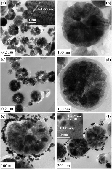 | ||
| Fig. 1 TEM images of (a, b) Fe3O4 particles, (c, d) Fe3O4@SiO2 microspheres, (e) Fe3O4@SiO2@(PEI–Au)10 microspheres (f) Fe3O4@SiO2@(PEI–Au)5 microspheres. Inset (a) and (f) are the HRTEM images for the Fe3O4 particles and Fe3O4@SiO2@ (PEI–Au)5 microspheres, respectively. | ||
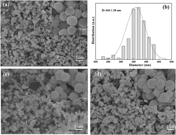 | ||
| Fig. 2 SEM images of (a) Fe3O4 particles, (c) Fe3O4@SiO2 microspheres, (d) Fe3O4@SiO2@(PEI–Au)10 microspheres, and (b) size distribution histogram of the Fe3O4 particles. Inset (a), (c), (d) are high-magnification SEM images, respectively. | ||
To deposit Au NPs, a versatile LbL assembly was used for the adsorption of PEI–Au multilayer films on to the Fe3O4@SiO2 magnetic microspheres. The assemble process were monitored by FT-IR spectra, as shown in Fig. 3a. The band at 580 cm−1 is assigned to the vibration of the Fe–O bonds for Fe3O4 particles. After coating a SiO2 shell, a new band at 1100 cm−1 appears which is assigned to the vibration of the Si–O bonds. After assembly of PEI–Au multilayer films, two obvious bands at 2860 and 2927 cm−1 appear associated with C–H stretching of the PEI polyelectrolyte backbone (see Fig. S1†). With the growth of PEI–Au bilayers, the intensity of Fe–O and Si–O bands reduces, because the polyelectrolyte multilayer films are very effective at screening the Fe–O and Si–O bands. The same phenomenon has also been reported elsewhere.16 However, the intensity of the C–H bands exhibits a slight increase conversely, suggesting the successful assembly of PEI–Au multilayer films on Fe3O4@SiO2 microspheres. The pre-synthesized Au NPs have a uniform size of ∼12 nm (Fig. S2†) and they are negative due to the capping citrate groups. Resultantly, the Au NPs are strongly attracted to the PEI polycations through electrostatic interactions, which makes the assembly of PEI–Au multilayer films feasible and effective. TEM image of the Fe3O4@SiO2@(PEI–Au)10 microspheres (Fig. 1e) clearly shows that the Au NPs are deposited on the surface of the Fe3O4@SiO2 microspheres. Since the Au NPs are deposited in different PEI layers, the distance from the Au NPs to the Fe3O4@SiO2 microspheres is not equal. Owing to the low contrast, the PEI polycations confirmed by FT-IR could hardly be detected by TEM. Remarkably, the loading amount of Au NPs can be readily regulated through controlling the assembly number of PEI–Au bilayers. The Au content determined by ICP shows a linear increase with the growth of PEI–Au bilayers (see Fig. S3†). When the assembly number of PEI–Au bilayers reduced to 5, the Au NPs deposited on the Fe3O4@SiO2 microspheres are much more sparse compared with Fe3O4@SiO2@(PEI–Au)10 sample (Fig. 1f). The HRTEM image clearly indicates that the Fe3O4 core and Au NPs are both highly crystallized (inset Fig. 1f). The SEM image for Fe3O4@SiO2@(PEI–Au)10 sample shows that the regular spherical shape is preserved (Fig. 2d) and some Au NPs are scattered on the surface of the Fe3O4@SiO2 microspheres (inset Fig. 2d). UV-vis absorption spectra (Fig. 3b) of Au colloids solution show a maximum absorbance at 520 nm, characteristic of the Au NPs with the size of 12–15 nm in aqueous solution.17 In contrast, the Fe3O4@SiO2@(PEI–Au)10 microspheres dispersion exhibits a broad adsorption band at ∼715 nm, indicating a red shift of about 194 nm, due to the deposition of Au NPs in PEI polyelectrolyte.18 The crystalline structures of the Fe3O4 particles and the magnetic hybrids were determined by XRD. As presented in Fig. 3c, the characteristic diffraction peaks can be observed for Fe3O4 particles, indicating their well crystallized structure. After coating a SiO2 shell, a new broad peak around 23° appears because of the existence of amorphous silica. For Fe3O4@SiO2@(PEI–Au)10 microspheres, new peaks indexed to a fcc Au crystal are observed, confirming the successful deposition of Au NPs. The representative EDS spectrum for Fe3O4@SiO2@(PEI–Au)10 sample also confirms the existence of Fe, Si and Au elements, which is consistent with TEM and XRD results (Fig. 3d).
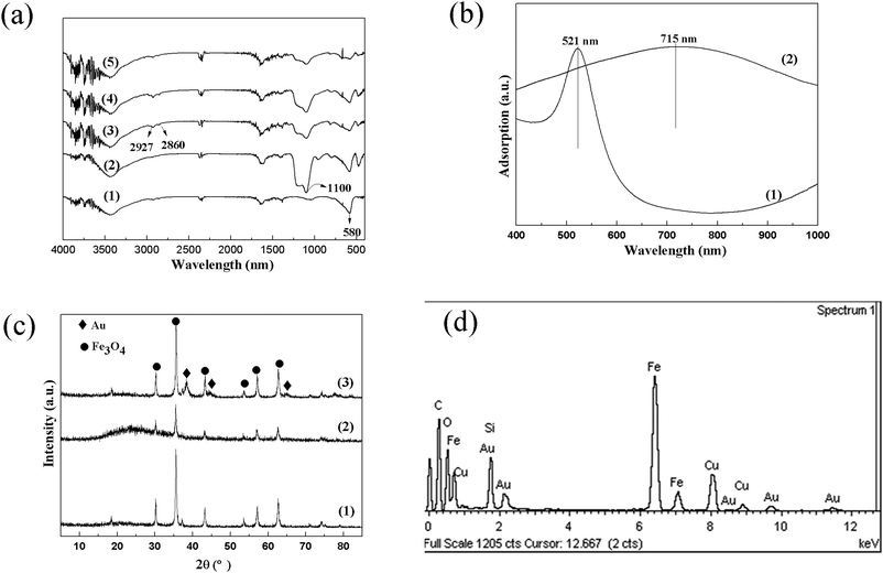 | ||
| Fig. 3 (a) FT-IR spectra of (1) Fe3O4, (2) Fe3O4@SiO2, (3) Fe3O4@SiO2@(PEI–Au)5, (4) Fe3O4@SiO2@(PEI–Au)8, and (5) Fe3O4@SiO2@(PEI–Au)10; (b) UV-vis spectra of (1) Au colloids aqueous dispersion and (2) Fe3O4@SiO2@(PEI–Au)10 microspheres aqueous dispersion; (c) XRD patterns of (1) Fe3O4, (2) Fe3O4@SiO2, and (3) Fe3O4@SiO2@(PEI–Au)10 microspheres; (d) representative EDS spectrum of Fe3O4@SiO2@(PEI–Au)10 microspheres. | ||
The magnetic properties of the hybrid composites were studied by a vibrating sample magnetometer at 300 K, which is shown in Fig. 4a. The magnetic curves show that all the samples are superparamagnetic at room temperature. No remanence or coercivity is detected due to the fact that the Fe3O4 particles are composed of ultrafine magnetic nanocrystals. The saturation magnetization value of Fe3O4, Fe3O4@SiO2 and Fe3O4@SiO2@(PEI–Au)10 are 80.8, 60.2 and 56.5 emu g−1, respectively. The Fe3O4@SiO2@(PEI–Au)10 sample shows a (∼6.1%) decrease in the mass magnetization compared with the Fe3O4@SiO2 sample, which is consistent with the amount of non-magnetic PEI polyelectrolyte and Au NPs (5.7%) deposited on the Fe3O4@SiO2 microsphere. Though, the saturation magnetization shows a decrease after deposition the SiO2 shell and PEI–Au multilayer films, the hybrid composite can still be separated quickly from the solution, within 30 s, using a magnet (see Fig. 4b). This promises a facile magnetic separation for their practical application in catalysis. Moreover, the superparamagnetic property helps to prevent the Au-loaded magnetic microspheres from aggregation, which is also important for maximizing the exposure of the catalyst for efficient liquid phase catalysis.
 | ||
| Fig. 4 (a) The magnetic hysteresis loops of (1) Fe3O4, (2) Fe3O4@SiO2, (3) Fe3O4@SiO2@(PEI–Au)10; (b) The separation process of Fe3O4@SiO2@(PEI–Au)10 microspheres from solution with a magnet. | ||
We firstly chose the reduction of 4-NP in the presence of NaBH4 as a model system to demonstrate the catalytic performance of the hybrid microspheres as a recoverable catalyst. We are aware of the fact that nitrophenols are among the most common organic pollutants in industrial and agricultural waste water.19 However, 4-AP is an important intermediate for the manufacture of analgesic and antipyretic drugs. So the study on the reduction of 4-NP to 4-AP becomes much more fascinating both from the point of pollution abatement and industrial application. The reduction can be achieved by catalytic hydrogenation of 4-NP in ethanol at relatively high temperature and high hydrogen pressure.20 However, due to reasons of energy saving, safe operation, and avoiding the use of organic solvents, it may be interesting and meaningful to develop the process for the conversion of 4-NP to 4-AP in aqueous solution under mild conditions. Moreover, the substrates and products of this reaction can be easily detected by spectroscopic methods, and there is no appreciable byproduct formation.
Fig. 5 shows the UV-vis spectra for the reduction of 4-NP measured at 5 min intervals during the progress of the reaction with and without the Fe3O4@SiO2@(PEI–Au)10 catalyst. Since the concentration of the Fe3O4@SiO2@(PEI–Au)10 microspheres in the reaction system is very low, the measurement of the absorption spectra of 4-NP and the reduction product 4-AP was not disturbed by the light scattering of the catalyst particles. As the concentration of BH4− ion, used as reductant, largely exceeds that of 4-NP, it remained essentially constant throughout the reaction. Therefore, the successive decrease of peak density at 400 nm with time can be used to calculate the rate constant.21 This peak is attributed to the presence of 4-nitrophenolate ions in alkaline condition caused by the addition of NaBH4. Without a Au catalyst, such a peak shows a slight change with time (see Fig. 5a), which suggests that the reduction reaction proceeds extremely slowly without a catalyst, which is in accordance with the previous reports.21,22 However, when a small amount of Fe3O4@SiO2@(PEI–Au)10 catalyst was introduced, the 4-nitrophenolate ion peak at 400 nm depletes dramatically with time and a new 4-AP peak at 300 nm appears concomitantly (Fig. 5b). After 20 min, the original bright-yellow solution becomes visually colorless and the reaction is almost completed. As the concentration of NaBH4 was used in excess, the reaction can be considered to be a pseudo first order and the apparent rate constant is calculated by plotting the −lnA400 (negative logarithm of the absorbance at 400 nm) vs. time. The plots (inset Fig. 5a and b) both show nearly straight lines and the apparent rate constants values are calculated to be (2.95 ± 0.40) × 10−3 and 0.271 ± 0.028 min−1 in absence and presence of Au catalyst, respectively. After addition of the Au catalyst, the apparent rate constant is nearly 92 fold. The Au NPs used in the catalysis is 7.5 × 10⁻⁴ mmol and correspondingly the normalized rate constant (knor) for this reaction is calculated to be 6.02 mmol−1 s−1 (see entry 1 in Table 1). Such a value is much higher than the recently reported normalized rate constant of 2.04 mmol−1 s−1.23
 | ||
| Fig. 5 Spectral change of 4-NP during the reaction between 4-NP and NaBH4 at 25 °C without (a) and with (b) Fe3O4@SiO2@(PEI–Au)10 catalyst. The insets are the corresponding pseudo-first-order plot of −lnA400versus time. | ||
| Reactions | Entry | Substrates | T (°C) | Au used (mmol) | Absence of Au | Presence of Au | k nor (mmol−1 s−1) | ||
|---|---|---|---|---|---|---|---|---|---|
| k (min−1) | Error σ | k (min−1) | Error σ | ||||||
| Organic reduction reactions | 1 | 4-NP | 25 | 0.75 × 10⁻³ | 2.95 × 10⁻³ | 3.98 × 10⁻⁴ | 0.271 | 0.028 | 6.02 |
| 2 | 3-NP | 3.35 × 10⁻³ | 5.82 × 10⁻⁴ | 0.044 | 0.003 | 0.98 | |||
| 3 | 2-NP | 3.10 × 10⁻³ | 3.15 × 10⁻⁴ | 0.11 | 0.012 | 2.44 | |||
| 4 | 2-CH3-4-NP | 3.50 × 10⁻³ | 1.23 × 10⁻⁴ | 0.042 | 0.005 | 0.93 | |||
| 5 | 3-CH3-4-NP | 3.31 × 10⁻³ | 4.66 × 10⁻⁴ | 0.032 | 0.001 | 0.07 | |||
| 6 | 2-Cl-4-NP | 3.24 × 10⁻³ | 4.43 × 10⁻⁴ | 0.053 | 0.002 | 1.17 | |||
| Inorganic reduction reaction | 7 | K3Fe(CN)6 | 40 | 1 × 10⁻³ | 2.36 × 10⁻⁴ | 0.56 × 10⁻⁴ | 1.97 × 10⁻³ | 0.88 × 10⁻⁴ | 0.033 |
The catalytic reduction was also successful in the cases of other nitrophenols, such as 3-NP, 2-NP and so on (entries 2–6 in Table 1). Without catalysts, the reduction reactions of nitrophenols can not proceed smoothly. However, the rate constant values increased greatly after addition of a small amount of the Au catalysts. In the experiments, when a freshly prepared aqueous solution of NaBH4 was added to the reaction mixture containing an aqueous solution of nitrophenol and Au catalyst, nitrophenolate ions were formed; these could be visualized by the red shifting of the peak by 60–85 nm. The formation and stability of nitrophenolate ion have great influence on the rate of reduction.
It is well known that 4- and 2-nitrophenolate ions are more stable than the 3-nitrophenolate ion.24 In the case of 4-nitrophenolate ion, the “negative” charge on oxygen is delocalized throughout the benzene ring (conjugation effect) and becomes resonance-stabilized. In the 2-nitrophenolate ion, the “negative” charge on oxygen is also delocalized throughout the benzene ring but not so effectively as in the 4-nitrophenolate ion. The –I effect (inductive effect) of the nitro group is also present, but due to steric hindrance it is less effective and therefore less stable than former isomer. In the 3-nitrophenolate ion, there is no conjugation effect, only the –I effect of the nitro group is present. Therefore, the rate of reduction of the nitrophenols followed the order 4-NP > 2-NP > 3-NP, which is in accordance with our results (see Table 1). From entries 4–6, it can be seen that the reduction rate of 4-NP decreased dramatically no matter the electron acceptor (Cl) or electron donor (CH3) substituent groups were introduced in the ortho- and meta-position because of the steric hindrance.
In addition, the catalytic activity is found to be relevant to the assembly number of the PEI–Au bilayers in our work. For the 4-NP reduction reaction, the apparent rate constant value increases slightly with the growth of PEI–Au bilayers on the magnetic microspheres, which can be seen in Fig. S4.† The mechanism for such an increase in catalytic activity is currently not very clear. Maybe the particular structure of the hybrid composite is beneficial for the catalysis. The PEI polyelectrolyte multilayers assembled on the Fe3O4@SiO2 microspheres exhibit a porous structure and therefore the Au NPs deposited in the PEI polyelectrolyte are readily accessible to 4-NP and BH4−. So the catalytic activity increases slightly when more PEI–Au bilayers are assembled. Such a result is consistent with the previous report, where the conversion percent of 4-NP increased as a function of the number of bilayers deposited for the PEI–Au NPs films.15 Hereafter, we use Fe3O4@SiO2@(PEI–Au)10 catalyst to investigate the catalytic performance in inorganic reduction reaction as well as the reusability of such a catalyst.
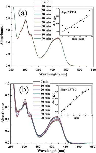
The aforesaid discussion indicates that the obtained Au catalyst in our work exhibits great catalytic performance in the organic reduction reaction of various nitrophenols by NaBH4. However, it is noteworthy that reports are rare on the application of Au catalysts in the inorganic reduction reaction of Fe(CN)63− to Fe(CN)64− by S2O32−.25 Thus, the catalytic property of Fe3O4@SiO2@(PEI–Au)10 catalyst was also tested in the typical redox reaction between Fe(CN)63− and S2O32− at 40 °C in our work. The optical spectra of solution in absence and presence of the Fe3O4@SiO2@(PEI–Au)10 catalyst was also monitored with respect to time using UV-vis adsorption spectrometer and the results are presented in Fig. 6. The reaction did not occur in absence of catalyst and no obvious spectral change is observed over 90 min (Fig. 6a). After introduction of the Fe3O4@SiO2@(PEI–Au)10 catalyst, the Fe(CN)63− peak at 420 nm shows a gradual decrease with respect to time, indicating the reduction reaction proceeds smoothly (Fig. 6b). The apparent rate constant value is calculated to be (1.97 ± 0.088) × 10−3 min−1 (inset Fig. 6b) from the slope of the plot of −lnA420 against time. Such a value is almost 8 times as high as the rate constant value of the blank reaction without Au catalyst (inset Fig. 6a). The corresponding normalized rate constant (knor) is calculated to be 0.033 mmol−1 s−1 (entry 7 in Table 1), which is much lower than that of the 4-NP reduction reaction. Such results are consistent with the previous report, in which the Au NPs also exhibited better catalytic performance in 4-NP system than in Fe(CN)63− system.23
 | ||
| Fig. 6 Spectral change of Fe(CN)63− during the reaction between Fe(CN)63− and S2O32− at 40 °C without (a) and with the Fe3O4@SiO2@(PEI–Au)10 catalyst. The insets are the corresponding pseudo-first-order plot of −lnA420versus time. | ||
Separation of expensive catalytic NPs from the reaction mixture and regeneration of their catalytic properties are very difficult and becoming big issues to the industry. Notably, the synthesized Fe3O4@SiO2@(PEI–Au)n catalysts in our work can be separated simply with a magnet within 30 s and reused several times by washing with ultrapure water followed by drying at 50 °C. To confirm this, 5 cycles of the above two reactions were performed with Fe3O4@SiO2@(PEI–Au)10 as the catalyst and monitored with UV-vis adsorption spectrometer. The obtained apparent rate constant for each cycle is showed in Fig. 7. The results show that the rate constants in the two model reactions both preserve 90% of the initial value after recycle 5 times. The isolated products obtained after the magnetic separation were analyzed by ICP. Results show that negligible Au leaching of our catalysts occurs, which demonstrates the high stability of PEI–Au multilayer films on a Fe3O4@SiO2 magnetic support, and the high performance of the magnetic separation. The slight loss of rate constant in 5th cycle is due to some loss of catalyst in the repeated magnetic separation, washing and drying process.
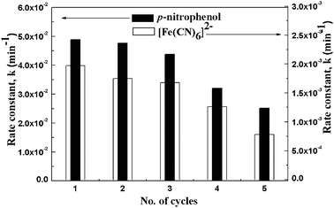 | ||
| Fig. 7 Rate constant values (k) of the catalytic reduction reactions of 4-NP and Fe(CN)63− in five different cycles using Fe3O4@SiO2@(PEI–Au)10 catalyst. | ||
Conclusions
We successfully prepared a bifunctional hybrid composite by the deposition of the pre-synthesized Au colloids and PEI polyelectrolyte on the Fe3O4@SiO2 magnetic microspheres through LbL assembly technique. The well designed microspheres have well-defined core–shell nanostructures, with a Fe3O4 core (360 nm) and a SiO2 shell (25 nm) as well as the confined catalytic Au NPs with a uniform diameter of 12 nm. The obtained bifunctional microspheres show an excellent catalytic performance in organic and inorganic reduction reactions with good reusability. Therefore, such functional hybrid microspheres hold great promise as a novel Au based catalyst system for various catalytic reactions. The catalysts reported here show a superparamagnetic property with a saturation magnetization value 56.5 emu g−1. So they can be efficiently recovered by magnetic separation, with negligible Au leaching to the solution. This separation procedure is an effective and green alternative to the conventional separation techniques, such as filtration and centrifugation, since it is a fast, clean, waste minimizing and low energy consuming procedure. Moreover, the design concept of the bifunctional hybrid composite can be intended to the fabrication of other component systems for potential applications, such as catalysis, nanoreactors, and sensors.Acknowledgements
This research was financial supported by 973 Program (2011CB932504, 2007CB815303), NSFC (20731005, 20821061, and 91022007), Fujian Key Laboratory of Nanomaterials (2006L2005), CAS and FJIRSM (SZD07002).References
- (a) E. V. Shevchenko, D. V. Talapin, C. B. Murray and S. O’Brien, J. Am. Chem. Soc., 2006, 128, 3620 CrossRef CAS; (b) F. X. Redl, K. S. Cho, C. B. Murray and S. O’Brien, Nature, 2003, 423, 968 CrossRef CAS.
- (a) A. Quarta, R. Di-Corato, L. Manna, S. Argentiere, R. Cingolani, G. Barbarella and T. Pellegrino, J. Am. Chem. Soc., 2008, 130, 10545 CrossRef CAS; (b) M. Barbic, Nano Lett., 2005, 5, 187 CrossRef CAS; (c) X. Gao, K. M. K. Yu, K. Y. Tam and S. C. Tsang, Chem. Commun., 2003, 2998 RSC.
- (a) S. Mann, Nat. Mater., 2009, 8, 781 CrossRef CAS; (b) S. C. Warren, F. J. Disalvo and U. Wiesner, Nat. Mater., 2007, 6, 156 CrossRef CAS; (c) S. A. Jenekhe and X. L. Chen, Science, 1998, 279, 1903 CrossRef CAS; (d) F. Caruso, R. A. Caruso and H. Möhwald, Science, 1998, 282, 1111 CrossRef CAS; (e) Z. H. Xu, Y. L. Hou and S. H. Sun, J. Am. Chem. Soc., 2007, 129, 8698 CrossRef CAS; (f) Y. H. Deng, D. W. Qi, C. H. Deng, X. M. Zhang and D. Y. Zhao, J. Am. Chem. Soc., 2008, 130, 28 CrossRef CAS; (g) Y. H. Deng, C. H. Deng, D. W. Qi, C. Liu, J. Liu, X. M. Zhang and D. Y. Zhao, Adv. Mater., 2009, 21, 1377 CrossRef CAS; (h) Y. H. Deng, Y. Cai, Z. K. Sun, J. Liu, C. Liu, J. Wei, W. Li, C. Liu, Y. Wang and D. Y. Zhao, J. Am. Chem. Soc., 2010, 132, 8466 CrossRef CAS.
- N. Sounderyal and Y. Zhang, Recent Pat. Biomed. Eng., 2008, 1, 34 Search PubMed.
- (a) J. H. Fendler, NPs and Nanostructured Films: Preparation, Characterization and Applications, Wiley-VCH, Weinhein, Germany, 1998 Search PubMed; (b) G. Schmid, in Nanoscale Materials in Chemistry, ed. K. J. Klabunde, Wiley-Interscience, New York, 2001, pp. 15–59 Search PubMed.
- M. Zhao, L. Sun and R. M. Crooks, J. Am. Chem. Soc., 1998, 120, 4877 CrossRef CAS.
- (a) H. Bönnemann and R. M. Richards, Eur. J. Inorg. Chem., 2001, 2455 CrossRef CAS; (b) C. N. R. Rao, G. U. Kulkarni, P. J. Thomas and P. P. Edwards, Chem.–Eur. J., 2002, 8, 28 CrossRef CAS; (c) Y. Li and M. A. El-Sayed, J. Phys. Chem. B, 2001, 105, 8938 CrossRef CAS.
- R. L. Oliveira, P. K. Kiyohara and L. M. Rossi, Green Chem., 2010, 12, 144 RSC.
- (a) J. P. Ge, T. Huynh, Y. X. Hu and Y. D Yin, Nano Lett., 2008, 8, 931 CrossRef CAS; (b) Z. F. Wang, P. F. Xiao, B. Shen and N. Hea, Colloids Surf., A, 2006, 276, 116 CrossRef CAS; (c) D. K. Yi, S. S. Lee and J. Y. Ying, Chem. Mater., 2006, 18, 2459 CrossRef CAS.
- (a) Y. C. Chang and D. H. Chen, J. Hazard. Mater., 2009, 165, 664 CrossRef CAS; (b) R. Abu-Reziq, H. Alper, D. S. Wang and M. L. Post, J. Am. Chem. Soc., 2006, 128, 5279 CrossRef; (c) Y. J. Jiang, J. H. Jiang, Q. M. Gao, M. L Ruan, H. M. Yu and L. J. Qi, Nanotechnology, 2008, 19, 075714 CrossRef.
- (a) G. Decher, Science, 1997, 227, 1232 CrossRef; (b) G. Decher and J. D. Hong, Makromol. Chem., Macromol. Symp., 1991, 46, 321 Search PubMed.
- Y. H. Wang and J.-K. Lee, J. Mol. Catal. A: Chem., 2006, 263, 163.
- J. P. Ge, Y. X. Hu, M. Biasini, W. P. Beyermann and Y. D. Yin, Angew. Chem., Int. Ed., 2007, 46, 4342–4345 CrossRef CAS.
- W. Stöber, A. Fink and E. Bohn, J. Colloid Interface Sci., 1968, 26, 62 CrossRef.
- D. M. Dotzauer, J. H. Dai, L. Sun and M. L. Bruening, Nano Lett., 2006, 6, 2268 CrossRef CAS.
- J. E. Wong, A. K. Gaharwar, D. Müller-Schulte, D. Bahadur and W. Richtering, J. Nanosci. Nanotechnol., 2008, 8, 4033 CrossRef CAS.
- S. Link and M. A. EI-Sayed, J. Phys. Chem. B, 1999, 103, 4212 CrossRef CAS.
- R. T. Tom, A. S. Nair, N. Singh, M. Aslam, C. L. Nagendra, R. Philip, K. Vijayamohanan and T. Pradeep, Langmuir, 2003, 19, 3439 CrossRef CAS.
- (a) S. Panigrahi, S. Basu, S. Praharaj, S. Pande, S. Jana, A. Pal, S. K. Ghosh and T. Pal, J. Phys. Chem. C, 2007, 111, 4596 CrossRef CAS; (b) T. Vincent and E. Guibal, Langmuir, 2003, 19, 8475 CrossRef CAS; (c) Y. C. Chang and D. H. Chen, J. Hazard. Mater., 2009, 165, 664 CrossRef CAS.
- (a) Y. Du, H. Chen, R. Chen and N. Xu, Appl. Catal., A, 2004, 277, 259 CrossRef CAS; (b) M. J. Vaidya, S. M. Kulkarni and R. V. Chaudhari, Org. Process Res. Dev., 2003, 7, 202 Search PubMed.
- (a) Y. Lu, Y. Mei, M. Drechsler and M. Ballauff, Angew. Chem., Int. Ed., 2006, 45, 813 CrossRef CAS; (b) S. K. Ghosh, M. Mandal, S. Kundu, S. Nath and T. Pal, Appl. Catal., A, 2004, 268, 61 CrossRef CAS; (c) Y. Mei, G. Sharma, Y. Lu, M. Drechsler, M. Ballauff, T. Irrgang and R. Kempe, Langmuir, 2005, 21, 12229 CrossRef CAS.
- (a) K. Hayakawa, T. Yoshimura and K. Esumi, Langmuir, 2003, 19, 5517 CrossRef CAS; (b) Y. Lu, Y. Mei, M. Ballauff and M. Drechsler, J. Phys. Chem. B, 2006, 110, 3930 CrossRef CAS; (c) Y. Lu, Y. Mei, R. Walker, M. Ballauff and M. Drechsler, Polymer, 2006, 47, 4985 CrossRef CAS.
- D. Jana, A. Dandapat and G. De, Langmuir, 2010, 26, 12177 CrossRef CAS.
- I. L. Finar, Organic Chemistry. The Fundamental Principles, 6th edn, 1973, vol. 1, ELBA, p. 702 Search PubMed.
- (a) P. L. Freund and M. Spiro, J. Phys. Chem., 1985, 89, 1074 CrossRef; (b) P. L. Freund and M. Spiro, J. Chem. Soc., Faraday Trans. 1, 1986, 82, 2277 RSC.
Footnote |
| † Electronic supplementary information (ESI) available. See DOI: 10.1039/c1cy00096a |
| This journal is © The Royal Society of Chemistry 2011 |