Received
14th October 2010
, Accepted 21st January 2011
First published on 17th February 2011
Abstract
This study attempts to elucidate the selectivity of photo-degradation of Rhodamine B (Rh–B) over zirconia-incorporated TiO2 (ZIT) by UV light, through a comparison of the photocatalytic activities of pure TiO2 (Degussa P25) and ZIT nanoparticles. The incorporated atomic ratio of Zr/Ti in ZIT is chosen at three levels: i.e. Zr/Ti = 68.01% (maximum, denoted as ZIT-1), Zr/Ti = 15.94% (medium, denoted as ZIT-3), and Zr/Ti = 1.88% (minimum, denoted as ZIT-4). The selective photo-degradation of Rh–B over ZIT occurs in two routes. They are N-de-ethylation and de-carboxylation. The photo-degradation N-de-ethylation of Rh–B is generally observed in an anatase-structured titania domain. However, the photo-catalytic de-carboxylation of Rh–B has not been reported for the titania-based photocatalysts. The spectra deconvolution data of solid state FT-IR suggest that the ZrO2–TiO2 matrix is responsible for the photo-catalytic de-carboxylation of Rh–B. The typical photocatalytic rate constants (kcat) of Rh–B over P25 (0.389 min−1), ZIT-1 (0.945 min−1), ZIT-3 (1.755 min−1), and ZIT-4 (1.197 min−1) are in the ratio 0.22![[thin space (1/6-em)]](https://www.rsc.org/images/entities/char_2009.gif) :0.51:1.00:0.68. The kcat of ZIT is 2.78 to 4.89 times that of P25. The highest catalytic efficiency is not achieved by the sample having the highest zirconia doping. Based on the experimental data, the optimal incorporation amount of ZrO2 in ZIT for photo-degradation of Rh–B is Zr/Ti = 15.94%.
:0.51:1.00:0.68. The kcat of ZIT is 2.78 to 4.89 times that of P25. The highest catalytic efficiency is not achieved by the sample having the highest zirconia doping. Based on the experimental data, the optimal incorporation amount of ZrO2 in ZIT for photo-degradation of Rh–B is Zr/Ti = 15.94%.
Introduction
Many governments list aromatic compounds and their derivatives as priority pollutants because of their ubiquity in the urban atmosphere, and their strong effects in causing cancer-related diseases.1 Unfortunately, aromatic compounds have a very stable resonance structure with respect to chemical attack under ambient conditions.2 Hence, the degradation of aromatic compounds and their derivatives is still a challenge in the fields of catalytic and environmental chemistry. Over the few past decades, because of its high stability and strong oxidizing potential of photogenerated holes (∼+2.9 eV),3 the irradiated TiO2 has been attracted considerable interest to investigate the potential use in the destruction of pollutants for environmental remediation.4–6 The use of TiO2 and oxygen is a green approach for the treatment of volatile organic pollutants under ambient conditions. However, the rapid recombination of photogenerated electrons (e−) and holes (h+) decreases the photocatalytic efficiency of TiO2. Much effect has been made to improve its efficiency by surface modification using a metal oxide, such as ZrO2, Al2O3, and SiO2, as a charge transfer catalyst (CTC), forming a binary photocatalysts.7–11 Generally, the surface Lewis acidity of titania is determined by the concentration of surface hydroxyl groups. These surface hydroxyl groups can trap photogenerated holes (h+), and then use these trapped holes (h+) to oxidize adsorbed molecules.11,12 The ability to trap the photogenerated electron (e−) and/or hole (h+) enables CTC to adjust the surface Lewis acidity. The surface sites with higher acidities offer better adsorption capability, and more polarized states of higher acidity sites favour the trapping of holes. Consequently, the increase in the capability to adsorb target compounds enhances the photocatalytic degradation efficiency of binary photocatalyst.7,11 Therefore, a rational approach to improving the catalytic efficiency of binary nanocomposite photocatalyst is to dope the photocatalysts with optimal amount of CTC.7,11
In the literature, available titania-zirconia aerogel materials are synthesized with a high Zr/Ti ratio (∼30% to 90%) and a low pore volume (1.36–2.14 ml g−1).13 The high concentration of zirconia makes the distribution of Ti and Zr ions almost homogeneous. The large difference between the ionic radii of Zr4+ ion (72 pm) and Ti4+ ion (60.5 pm) distorts the lattice of the crystalline titania anatase phase.11 The presence of a pure anatase phase is responsible for the photo-generation of electrons (e−) and holes (h+) under UV irradiation.11,14–17 Without this crystalline anatase phase, the photo-generation of e–h pair can not be initialized.
This study reports on the new preparation of a binary nanocomposite photocatalyst: ZrO2 incorporated TiO2 (ZIT) nanoparticles with a tunable Zr/Ti atomic ratio from 1.88% to 68.1% via a non-aqueous route. Basically, in the titania-zirconia mixed phase, the Ti4+ and Zr4+ ions are connected to each other tetrahedrally through the oxygen atoms.7,9 Because of the obvious difference between the partial charges of Zr4+ (+0.79) and Ti4+ (+0.65), the local electropositive charge is increased by introducing one Zr4+ ion into the tetrahedral position. The unbalanced local charge enables the Zr4+ ion to attract any available electron density through the [![[triple bond, length as m-dash]](https://www.rsc.org/images/entities/char_e002.gif) Ti–O–Zr] bonding structure.7,11 The spontaneous reduction of Zr4+ ions to Zr3+ ions with the charges provided by the [Ti–O–] occurs. This physical property of the Zr4+ ion enables it to delay the recombination of photogenerated electrons (e−) and holes (h+) that are created from the crystalline TiO2 domain by UV-vis irradiation.11,14 Therefore, the photocatalytic activity of the TiO2-based composite catalyst is enhanced. Additionally, the use of aprotic ethylene glycol (EG) as a solvent in the synthesis of ZIT can successfully interrupt the reverse reaction, i.e. hydrolysis reaction.7,11 The yield of products usually exceeds 75 wt%.
Ti–O–Zr] bonding structure.7,11 The spontaneous reduction of Zr4+ ions to Zr3+ ions with the charges provided by the [Ti–O–] occurs. This physical property of the Zr4+ ion enables it to delay the recombination of photogenerated electrons (e−) and holes (h+) that are created from the crystalline TiO2 domain by UV-vis irradiation.11,14 Therefore, the photocatalytic activity of the TiO2-based composite catalyst is enhanced. Additionally, the use of aprotic ethylene glycol (EG) as a solvent in the synthesis of ZIT can successfully interrupt the reverse reaction, i.e. hydrolysis reaction.7,11 The yield of products usually exceeds 75 wt%.
Experimental
(a) Chemicals
Zirconium(IV)oxide chloride octahydrate (ZOC), and Titanium(IV)butoxide (TBO) were purchased from Fluka. Tetrapropylaminebromide (TPAB) was got from Lancaster. Rhodamine B (95%, Aldrich) and reagent-grade ethylene glycol (EG, 99% Showa) were used without any further purification. HPLC grade methanol and reagent grade ethanol were obtained from Aldrich, and were used as supplied.
(b) Synthesis and characterization of ZIT
The ZIT photocatalyst was synthesized by the reaction of ZOC, TBO, and template TPAB in EG. A typical synthesis route is described as follows. TPAB 2.0 g was mixed with 30 mL EG in a tri-neck bottle, and was stirred for 20 min to allow the template TPAB to dissolve completely in EG. The starting reagents ZOC 0.189 g and TBO 2.0 mL (molar ratio = 0.1:1) were added into the EG/TPAB solvent, respectively. One neck of the tri-neck bottle was equipped with a standard perpendicular condenser for refluxing reaction. The other two necks were sealed with either a septum or an adaptor. The temperature of solution was raised slowly from room temperature to refluxing temperature (165–175 °C) with stirring at a standard speed of 250 rpm. The colour of the solution was murky-white at the beginning of the reaction, and changed to clear liquid after 10 min refluxing. The colour of the solution remained clear for about 2 h, and then changed back to milky white again. The second colour change of the solution is an indicator of the beginning of the nucleation reactions of TBO and ZOC monomers.7,11 The first withdrawal (3 mL) was taken at the 4th h at the growth temperature. Aliquots (2–3 mL for each withdrawal) were taken at different time intervals in order to calibrate the crystal evolution status of ZIT by scanning electron microscopy (SEM). The size and quality of the ZIT nanoparticles were obtained by transmission electron microscopic (TEM) images, and powder X-ray diffraction (PXRD) patterns. Each withdrawn product was washed twice with 10 mL of ethanol, and then in 10 mL DI water to remove completely any template residue. The final white precipitate was dried as a powder for further investigation.
TEM images, high resolution TEM (HR-TEM) images, and energy dispersive X-ray analysis spectra (EDX) were collected on a JOEL 2010 HR equipped with an accelerating voltage of 200 kV. Samples were prepared by evaporation of a colloidal solution onto a Cu grid. SEM images were captured using a Hitachi S-3500N. Samples were deposited onto conducting carbon film and coated by Au ion-sputtering at room temperature. X-ray photoemission spectra (XPS) were obtained on a Physical Electronics ESCA PHI 1600 equipped with an Al/Mg dual anode. Samples were deposited on indium foil from ethanol solution and were allowed to dry in the atmosphere for several h. Powder X-ray diffraction (PXRD) data were carried by a Shimadzu X6000 using Cu-Kα1 radiation. Fourier transform infrared spectra (FT-IR) were collected on a Shimadzu 8400 spectrophotometer. Mass spectra were performed on a Finnigan LCQ advantage electrospray ion-trap mass spectrometer. Photoluminescence (PL) spectra were collected by a Hitachi F-2500 fluorescence spectrophotometer. All spectra were collected at room temperature.
Results
Generally, in a sol–gel reaction, the pH value, the concentration of H2O/reactants, and the refluxing temperature are the most important factors that could determine the structure and properties of the sol–gel derived inorganic net-work over wide ranges. In this study, since the amount of water in the sol–gel system is negligible, the effects of pH and the [H2O/reactant] ratio are excluded, but the reactant concentrations and the reaction time (kinetic factors) are considered carefully.
The synthetic conditions and results for ZIT are listed in Table 1. The rate of growth of ZIT nanocrystallites is highly dependent upon the competition between decomposition and nucleation of titania and zirconia crystalline seeds.18–21 When the reagents TBO and ZOC are added to the nucleophilic solvent EG. The solvent starts an SN2 attack to the TBO monomers and/or the ZOC monomers forming the intermediate adducts titanium glycolate and/or zirconium glycolate.22 The partial positive charge on titanium (+0.65) in TBO is known to be a little lower than that of zirconium (+0.79) in ZOC.7,11,15 The nucleophilic attack to TBO by EG should start a slightly latter than that to ZOC by EG. Nevertheless, because of the advantage in the concentration of TBO monomers, when the nucleation of zirconia is initialized, the bridging condensation and the joint polymerization of titania simultaneously begin in the solvent. This mutual competition mechanism makes the doping of ZrO2 into TiO2 difficult. The experiment shows that it takes 2 h to change back to milky white. The rate of formation of heterogeneous networks of the [Zr–O–Ti] bonding structure is very slow.7,11
The synthetic routes of samples 1, 3, and 4 were selected to study the amount of ZrO2 that was evolved into TiO2 at maximum (ZIT-1, Zr/Ti > 50%), medium (ZIT-3, 25% > Zr/Ti > 10%), and minimum (ZIT-4, Zr/Ti < 5%) concentrations. The results for the evolution of nanocrystals collected at different times from the three samples are provided in Table 2. After the addition of starting reagents ZOC, TBO, and template TPAB into solvent EG, the reaction temperature was set between 165–175 °C to favour the equilibrium between the nucleation of monomers and the decomposition of nano-crystallites. Although, this study does not provide conclusive evidence of the precise kinetics of nucleation and decomposition of nano-crystalline seeds and monomers, the equilibrium between the nucleation and decomposition of seeds is known to be highly dependent upon the temperature and the concentrations of the starting reagents.18–21 A suggested nucleation mechanism between ZOC and TBO monomers is offered in the following paragraph.
Table 2 Results of different time intervals for ZIT nanoparticles
| |
ZIT-1 (ZOC:TBO = 0.5:1) |
ZIT-3 (ZOC:TBO = 0.1:1) |
ZIT-4 (ZOC:TBO = 0.05:1) |
|
RC = Rectangular crystal.
Ac–np = Aggregated cluster of nanoparticles.
|
| 4 h |
RCa (V < 10 μm3) |
RCa (V < 10 μm3) |
RCa (V < 10 μm3) |
| 8 h |
RCa (V > 5 μm3) 55% < Zr/Ti < 65% |
RCa (V > 5 μm3) 10% < Zr/Ti < 15% |
RCa (V > 5 μm3) 1% < Zr/Ti < 3% |
| 16 h |
AC-npb 65% < Zr/Ti < 70% |
AC-npb 12% <Zr/Ti< 17% |
RCa (V > 5 μm3) 1% < Zr/Ti < 3% |
| 24 h |
AC-npb 65% < Zr/Ti < 70% |
AC-npb 12% < Zr/Ti < 17% |
AC-npb (d < 20 nm) 1% < Zr/Ti < 3% |
| 48 h |
AC-npb (d < 20 nm) 65%< Zr/Ti< 70% |
AC-npb (d < 20 nm) 12% < Zr/Ti < 17% |
AC-npb (d < 20 nm) 1% < Zr/Ti < 3% |
(II) Characterization of ZIT nanoparticles
(a) SEM and TEM.
SEM and TEM were utilized to characterize the identity of ZIT nanoparticles. All ZIT samples were characterized by the same method. A typical procedure for characterizing ZIT-3 is described below. The first and second samples of ZIT-3 were collected at the 4th h (ZIT-3-4h), and the 8th h (ZIT-3-8h) for determination of their size and quality by SEM. The SEM images indicated that the two samples had similar sizes (< 5 um3) and shapes (rectangular). Fig. 1(a) presents the SEM image of ZIT-3-8h. The morphology of ZIT-3-8h shown in the image is rectangular and includes several clear crystal planes. However, in the SEM micrographs for the products collected at the 16th h, ZIT-3-16h, Fig. 1(b), the rectangular-shaped crystals no longer exist. Instead, numerous of irregular aggregated spherical nanoparticles are observed. The rectangular crystals can not survive from the competition between the decomposition and nucleation of crystallites during this period. In order to minimize the surface energy, the shape of crystallites changes from rectangular to spherical, they grow to a tentative stable size (critical volume, Vc).18Fig. 1(c) and (d) show SEM images for products that are collected at the 24th h, ZIT-3-24h, and the 48th h, ZIT-3-48 h. The spherical nanoparticles are observed in both SEM images, which exhibit similar morphologies to those of ZIT-3-16h.
 |
| | Fig. 1 SEM images of (a) ZIT-3-8h, (b) ZIT-3-16h, (c) ZIT-3-24h, and (d) ZIT-3-48h. The morphology of ZIT-3-8h is rectangular with several clear crystal planes. The morphologies of ZIT-3-16h, ZIT-3-24h and ZIT-3-48h are irregularly aggregated spherical nanoparticles. | |
The TEM and high-resolution TEM (HR-TEM) images are used to study the crystallinity and detailed composition of these nanoparticles. A TEM image containing a great number of ZIT-3-48h nanoparticles is given in Fig. 2(a). Most of the nanoparticles shown in this TEM image are spherical or near spherical. The diameters of the individual nanoparticles, measured from the TEM image, range from 70 nm to 150 nm. A blow-up TEM image for the inset of Fig. 2(a) is provided in Fig. 2(b). In this image, the heterogeneous ZrO2 domains are randomly incorporated on the surface of TiO2 nanoparticle. However, the surface of nanoparticle is not fully covered by the heterogeneous ZrO2 domains. The selected area electron diffraction (SAED) of ZIT-3-48 h is a ring pattern, suggesting that ZIT-3-48h has a short-range crystalline structure (on the nanoscale).11,23 The qualitative composition of ZIT-3-48h is analyzed by energy dispersive X-ray spectrum (EDX) of TEM. The EDX spectrum of the nanoparticles is provided in Fig. 2(c). Two Ti peaks, (4.51 keV (Kα)) and 4.93 keV (Kβ)), and one Zr peak (1.49 keV (Kα)) are identified. The atomic ratio of Zr/Ti measured from the EDX for ZIT-3-48h is about ∼12–17%.
 |
| | Fig. 2 (a) A TEM image of ZIT-3-48h. The size distribution ranges from 80 nm to 150 nm. (b) A blow-up TEM image for the inset of Fig. 2(a). In this image, the heterogeneous ZrO2 domains randomly incorporated on the surface of TiO2 nanoparticle are clearly observed. (c) The corresponding EDX of TEM. Two Ti peaks, (4.51 keV (Kα)) and 4.93 keV (Kβ)), and one Zr peak (1.49 keV (Kα)) are identified. | |
The TEM and EDX spectra of the TEM qualitatively confirm the existence of Zr atoms in the TiO2 nanoparticles, and the ZrO2 domains are unevenly incorporated in ZIT-3 nanoparticle. By following the same characterization procedures, the detailed results collected from TEM images and the EDX spectra for ZIT-1, and ZIT-4 are provided in Table 2.
(b) X-Ray photo-emission spectra.
The [Zr–O–Ti] bonding structure and the quantitative Zr/Ti ratio of the final product (48 h) for ZIT-1, ZIT-3, and ZIT-4 nanocomposite photocatalysts were measured by X-ray photo-emission spectra (XPS). The locations of the peaks at XPS for ZIT-1, ZIT-3, and ZIT-4 are identical. The region-wise XPS scans of ZIT-3 from 580 to 440 eV and 370 to 20 eV are provided in Fig. 3(a) and (b), respectively. Following a correction for sample charging, the bonding energy (BE) values for TiO2 are Ti 2s = 566.0 eV, Ti 2p1/2 = 465 eV, Ti 2p3/2 = 458.8 eV, Ti 3s = 63.1 eV, Ti 3p = 37.8 eV, and O 1s = 529.9 eV, O 2s = 23.0 eV). The BE values for ZrO2 are Zr 3p1/2 = 347.3 eV, Zr 3p3/2 = 334.1 eV, Zr 3d = 182.9 eV, and Zr 4P = 32.8 eV. These data are in agreement with the values reported in the literature.24 The BE values for the Zr, Ti, and oxygen lines as well as the elemental atomic percentages are analyzed as a function of the atom ratio of Zr and Ti for the samples prepared from ZIT-1, ZIT-3, and ZIT-4. The microanalysis data show that the atomic ratio (Zr/Ti) of Zr (1.85%) to Ti (98.15%) in ZIT-4 is 1.88%. In ZIT-3 samples, the Zr/Ti ratio of Zr (13.75%) to Ti (86.25%) is 15.94%. In the ZIT-1 samples, the atomic ratio of Zr (40.48%), to Ti (59.52%) is 68.01%.
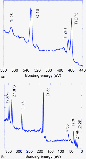 |
| | Fig. 3 Region wise scan XPS of ZIT-3. BE values (a) from 580 to 440 eV, (b) from 370 to 20 eV. | |
The XPS spectra demonstrate that the Zr4+ ions are surrounded by –O–Ti bonds, forming a [Zr–O–Ti] bonding structure in the ZrO2–TiO2.matrix. Such a hybridized ZrO2–TiO2 matrix may be created gradually during the evolution of nanoparticles. The dispensation of the ZrO2 moiety in TiO2 leads to the formation of mixed ZrO2–TiO2 phases through the hybridization of the boundary of TiO2 and ZrO2. Therefore, a hybridized TiO2–ZrO2 matrix with the [Zr–O–Ti] bonding structure is formed in the ZIT photocatalyst.8
(c) Powder X-ray diffraction (PXRD).
The gradual changes in the composition (i.e. Zr/Ti ratio) of ZIT nanoparticles that accompany variations in crystallinity were monitored by PXRD. The PXRD of ZIT-3 for samples collected from different time intervals are provided in Fig. 4(a). In the region of 20°–80° (two theta), seven peaks, matching the (101), (004), (200), (105), (204), (220), and (215) crystal phases of anatase TiO2 are obtained from ZIT-3-4h and ZIT-3-8h samples.23 In the PXRD of ZIT-3-16h and ZIT-3-24h, only the first three peaks, (101), (004), (200), are still recorded. The resultant diffraction pattern shows the anatase-structured TiO2 remains in both ZIT-3-16h and ZIT-3-24h, but the amorphous-like ZrO2–TiO2 matrix is created because of the high doping concentration of ZrO2. The diffraction pattern of ZIT-3-48h yields a similar result.
 |
| | Fig. 4 (a) The PXRD of ZIT-3 for samples collected from different time intervals. (b) The P-XRD of the samples collected at the 48th h for ZIT-1, ZIT-3, and ZIT-4, and calcined at 550 K for 4 h. (c) An obvious shift of peak (101) from two theta 25.5° (ZDT-4), to 25.3°, (ZDT-3), and finally to 25.2°, (ZDT-1) is observed, | |
In order to clarify the variation of the crystallinity of TiO2 and ZrO2–TiO2 that accompanies the change in Zr/Ti ratio, the products collected at the 48th h for ZIT-1, ZIT-3, and ZIT-4 were calcined at 550 K for 4 h. The P-XRD of the calcined samples are given in Fig. 4(b). Nine peaks associated with the crystalline phases of anatase-structured TiO2 are clearly recorded in the diffraction pattern of ZIT-3, and ZIT-4. The diffraction pattern of ZIT-1 includes only the most intensive (101) and (200) peaks. In the diffraction patterns of ZIT-3, and ZIT-4, the crystallinity of ZIT-3-48h, and ZIT-4-48h is restored after calcination at 550 K for 4 h, but the diffraction pattern of calcined ZIT-1-48h is unchanged. This result implies that the doping concentration of ZrO2 in ZIT-3, and ZIT-4 is not high enough for it to hybridize with whole domains of TiO2. Only partial domains of TiO2 are mixed with ZrO2 forming the ZrO2–TiO2 matrices. Pure TiO2 domain (major) and hybridized ZrO2–TiO2 matrix (minor) co-exist in the ZIT-3, and ZIT-4 samples. Nevertheless, the doping concentration of ZrO2 is high enough for it to mix with most TiO2 domains in ZIT-1 to form the amorphous-like ZrO2–TiO2 matrices. Only a little crystalline anatase structured TiO2 phase is present in ZIT-1. The main structure of ZIT-1 is amorphous-like ZrO2–TiO2 matrix, and the crystallinity of ZIT-1 can’t be improved by the calcination. The XRD data show that the crystallinity of ZIT nanoparticles can be tuned by adjusting the concentration of ZrO2 doping. A higher doping concentration of ZrO2 corresponds to lower crystallinity in ZIT nanoparticles.
As for the existence of the Ti–O–Zr chemical bond in the ZIT samples, the P-XRD pattern can offer a useful evidence. An obvious shift of peak (101) from two theta 25.5° (ZDT-4), to 25.3°, (ZDT-3), and finally to 25.2°, (ZDT-1) is observed, shown in Fig. 4(c). Such a peak shift is known to be induced by the change of lattice parameter of anatase-phased TiO2.23 Thus, the Ti–O–Zr chemical bond is believed to be formed in ZIT sample. The conclusion is consistent with the result derived from XPS spectra.
The commercial software, PEAKFIT, was acquired to deconvolute and to fit the spectral band of interest. The Gaussian and Lorentzian functions were selected to fit the spectral curves in this work. The R2 value (coefficient of determination) was always larger than 0.995. The data were smoothed by a 25% Fourier filtering transform (FFT), and the baseline was subtracted before the spectral deconvolution. The principal assumption in this model is that each of the component peaks corresponds to a typical mode of –OH group on the surface of ZIT nanoparticles. After the spectral deconvolution, all the overlapping peak areas and λmax will be resolved, which presumably will have a ratio corresponding to the different type of –OH groups on the surface of ZIT nanoparticle.
(a) Solid state infrared (IR) spectra.
A typical solid state infrared spectra (IR) spectrum of a ZIT photocatalyst has a very broad absorbance band of –OH functional group, with a band width of ∼3000 cm−1 to 3700 cm−1, suggesting the possibility of overlapped components.25,26 This broad band is not symmetric and its intensity varies with the concentration of hydroxyl groups dangling on the surface of the ZIT photocatalyst.25 The solid state infrared spectra (IR) of the three ZIT samples and P25 are provided in Fig. 5(a). The absorbance intensity of the –OH stretching is proportional to the concentration of zirconia doping in the ZIT nanoparticles, as predicated by the model proposed by Tanabe et al.6,27 The model assumes that the cation of the dopant oxide enters the lattice of its host oxide and retains its original coordination number.27 The coordination numbers of oxygen bonded to the dopant cation remains, and a charge imbalance is created. Thus, Brønsted sites (negative imbalance) and Lewis sites (positive imbalance) are expected to be formed.6 Zirconia is eight-fold coordinated with each oxygen bonded to four zirconia atoms. Titania is octahedrally coordinated with each oxygen bonded to three titanium atoms. If a zirconia atom enters a titanium lattice, then each of its eight bonds become attached to an oxygen that has only one other cation bond. Four valence electrons (on Zr) divided by eight bonds minus two available electrons on oxygen divided by two gives a charge imbalance of −1/6 per bond.6 Since the imbalance is negative, a proton is expected to associate with the near by oxygen atoms, and more surface hydroxyl groups will be initialized. Therefore, the absorbance intensity of the –OH mode is then increased.6,27
 |
| | Fig. 5 (a) A typical solid state infrared spectra (IR) spectrum of ZIT photocatalysts, band width = ∼ 3000 cm−1 to 3700 cm−1. The absorbance intensity of the -OH stretching is proportional to the doping concentration of zirconia in ZIT nanoparticles. (b) After deconvolution, a spectrum was judged to have three components, i.e. peak P1, peak P2, and peak P3 for ZIT-4 sample. (c) In the spectra deconvolution of P25, only two peaks, i.e. peak P1 and P2, are derived. | |
(b) Spectra deconvolution.
Theoretically, the starting parameters of the deconvolution should be set by trial and error. The curve-fitting program provided numerical values for baseline, amplitude, absorbing center, half-width, and function parameters. After deconvolution, a spectrum was judged to have three components, i.e. peak P1, peak P2, and peak P3 for ZIT samples, Fig. 5(b) shows the spectrum deconvolution result of ZIT-4. The shortest wavelength peak is peak P1 (λmax ∼3380 cm−1), which is proposed to the –OH bands of water molecules strongly absorbed on TiO2 based photocatalyst.26,28 The peak P2 (λmax ∼3590 cm−1) is generally attributed to the sum of the complicate spectral signature of the –OH groups present on different defect sites of both rutile and anatase phases.28 For the band of P3 (λmax ∼3670 cm−1), an assignment has been proposed to an isolated –OH group vibration on an anatase phase.28 Nevertheless, in this study, the experimental data show that the peak area of peak P3 is proportional to the doping amount of ZrO2. In the spectrum deconvolution of P25, given in Fig. 5(c), only two peaks, i.e. peak P1 and P2, are derived. The peak P3 is not evident in Fig. 5(c). Since there is no ZrO2 doping in P25, the absence of peak P3 in Fig. 5(c) implies that the P3 is initialized by ZrO2 doping. This assignment of the P3 peak is based on the information derived from TEM images and is theoretically supported by the PXRD and XPS data provided in previous paragraphs.
The solid state IR spectra of ZIT-1, and ZIT-4 were selected for further spectra deconvolution analysis. The deconvolution results are listed in Table 3. Three tendencies of peak areas are observed in the deconvoluted data: (1) The total peak areas show an augmentation of 38.94%, from ZIT-4 to ZIT-1. The augmentation of the total peak area suggests that the whole amount of –OH groups noticeably increases from ZIT-4 to ZIT-1. The experimental results support the assumption that the addition of zirconia in the ZIT can increase the number of surface hydroxyl groups of ZIT.7,11 (2) The increment of peak P3 from ZIT-4 to ZIT-1 is 2.24 times. Meanwhile, the peak area of peak P2 decreases about 9.3%. The data is consistent with the previous prediction that the increment of –OH peak area is contributed from the zirconia doping. (3) P25 is a zirconia-free photocatalyst, and peak P3 is not evident in P25 spectra. Therefore, the assignment of the P3 mode to the –OH vibration present on ZrO2 domains is reasonable.
Table 3 Re-convoluted peak areas in ZIT and P25 samples
| Sample |
Peak P1 |
Peak P2 |
Peak P3 |
Total area |
R
2
|
|
R
2 = 1 − SSE/SSM; R2 = coefficient of determination. SSE = sum of squares due to error, SSM = sum of squares of the mean. |
| ZIT-1 |
50.8 |
51.4 |
43.3 |
145.5 |
0.995 |
| ZIT-1 |
45.8 |
55.1 |
32.1 |
133.0 |
0.995 |
| ZIT-1 |
43.7 |
56.7 |
19.3 |
119.7 |
0.997 |
| P25 |
43.6 |
57.5 |
0 |
101.1 |
0.997 |
(IV) Photocatalytic degradation of Rh–B
The photoluminescence (PL) emission spectra were used to explore the adsorption ability and the efficiency of photocatalytic degradation of the organic pollutant Rh–B over ZIT-1 (Zr/Ti = 68.01%), ZIT-3 (Zr/Ti = 15.94%), ZIT-4 (Zr/Ti = 1.88%), and Degussa P25 (Zr/Ti = 0%).
(a) Selection of irradiation wavelength.
Generally, Rh–B is degraded by the photo-induced (e–h) pairs from photocatalysts (photocatalysis), and/or by the photo-excited electrons injected from Rh–B molecules to photocatalyst (photosensitization).29,30 Therefore, a suitable irradiation wavelength for the photo-degradation reaction must be carefully selected to prove that the degradation of Rh–B by the ZIT photocatalyst is an authentic photocatalysis reaction. Fig. 6 shows the diffuse reflectance spectra (DRS) of ZIT and Rh–B. The DRS of ZIT photocatalysts have similar shapes. The cut-off band gap of ZIT ranges from 420 nm (ZIT-4) to 405 nm (ZIT-1), which is far outside the absorption range of Rh–B, ∼460–600 nm. The DRS spectra demonstrate that the ZIT absorbs photos with wavelength of 420 nm (∼2.95 eV) or higher, and that Rh–B absorbs photons between 460 nm (2.69 eV) and 600 nm (2.07 eV). No region of overlap is recorded between the cut-off band gap of ZIT and the absorption range of Rh–B. The electron transfer from the dye molecule Rh–B to the photocatalyst ZIT, i.e. photosensitization activity, should be negligible, if the selected irradiation wavelength is shorter than 460 nm.
 |
| | Fig. 6 The diffuse reflectance spectrum (DRS) of ZIT and Rh–B. The DRS of ZIT photocatalysts are similar in shape. The cut-off band gap of ZIT ranges from 420 nm (ZIT-4) to 405 nm (ZIT-1), which is far outside the absorption range of Rh–B, ∼460 nm to 600 nm. No region is overlapped between the cut-off bang gap of ZIT and absorption range of Rh–B. | |
(b) Adsorption ability of Rh–B.
Each photocatalyst (100 mg) was immersed in 30 mL stock solution Rh–B (1 × 10⁻⁵ M, pH = 7.0 ± 0.1) for 60 min. The immersed photocatalyst was filtered out, and the filtrate was collected to measure the absorption ability of the photocatalysts by photoluminescence (PL) emission spectra. A major peak (λmax = 579 nm) between 530 and 660 nm was observed from all of the filtrates, and was associated with the emission of Rh–B, as shown in Fig. 7.29 The emission intensity of P25 filtrate was 93.5%, which was calculated from four emission spectra. The ratio of absorption for the Rh–B over P25 filtrate was 6.5%, after the emission intensity of filtrate was subtracted. The absorption ability of Rh–B over ZIT samples was derived using the same experimental route as was used for P25. The amount of Rh–B absorbed in 60 min followed the order, P25 (6.5%) < ZIT-4 (12.2%) < ZIT-3 (17.8%) < ZIT-1 (26.3%). The ability of photocatalysts to absorb Rh–B is proportional to the doping concentration of zirconia in the ZIT photocatalysts. For accuracy purpose, these results are still needed the correlation between surface area of the photocatalysts and adsorption amount of Rh–B molecules.
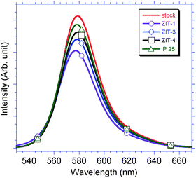 |
| | Fig. 7 (a) A major peak (λmax = 579 nm) between 530 and 660 nm was observed from the spectra of all filtrates, which is regarding to the emission of Rh–B. The order of adsorption ability for Rh–B is P25 (6.5%) < ZIT-4 (12.2%) < ZIT-3 (17.8%) < ZIT-1 (26.3%). | |
(c) Photocatalytic degradation of adsorbed Rh–B via UV irradiation.
Two photocatalytic degradation routes of absorbed Rh–B were experimentally explored. The first was utilized with a low [Rh-B]/[cat.] ratio, (Rh–B:cat. = 1:100). The second route was adopted with a high [Rh–B]/[cat.] ratio, (Rh–B:cat. = 1:0.67). Each photocatalyst (route 1 = 30 mg, route 2 = 10 mg) was immersed in 30 mL Rh–B stock solution (route 1 = 1 × 10⁻⁵ M, route 2 = 5 × 10⁻⁴ M). The immersed photocatalyst was bubbled with nitrogen before the irradiation by UV light (18 W, λ = 254 nm). The samples that were irradiated for only 20 min were the series “a” of samples. They were P25-a, ZIT-1-a, ZIT-3-a, and ZIT-4-a. The other samples, which were irradiated for 40, 60, 80, 100, and 120 min, were the “b”, “c”, “d”, “e”, and “f”, series of samples, and were used to measure the photo-decomposition rate of Rh–B as a function of time.
The collected solutions were filtrated and the filtrates were analyzed by PL emission spectra to determine the concentration of the non-decomposed Rh–B that remains in the filtrate. The excitation wavelength was set at 364 nm, and the emission spectra were collected with a resolution of 2.0 nm. A typical PL spectrum for photo-catalytic reduction of Rh–B over ZIT-3 is provided in Fig. 8(a). One major peak between 530 and 650 nm, λmax = 575 nm, was observed for all resulting solutions that were collected from 20 to 100 min under UV irradiation. The intensity of PL was normalized before the calculation of photocatalytic degradation rate constant (kcat) by varying the PL intensity. The blue shift of the λmax of PL peak is related to the N-de-ethylation of Rh–B to rhodamine.31 The photocatalytic degradation rate constant (kcat) is obtained from a plot of ln(c/c0) vs. time (min). The slope (R) is the (−)kcat. Time-evolved photo-degradation curves of the removal rates derived from the PL intensity are provided in Fig. 8(b) and Fig. 10(c). The kcat for the two degradation routes is as follows. In route 1, the kcat values of P25 (0.0041 min−1), ZIT-1 (0.0114 min−1), ZIT-3 (0.0211 min−1), and ZIT-4 (0.0141 min−1) are in the ratio 0.19:0.54:1.00:0.67, as shown in Fig. 10(b). In route 2, the kcat values of P25 (0.328 min−1), ZIT-1 (0.945 min−1), ZIT-3 (1.755 min−1), and ZIT-4 (1.197 min−1) are in the ratio 0.22:0.51:1.00:0.68, as shown in Fig. 8(c). The kcat value of route 2 is ∼83 times higher than that of route 1, but the degradation ratios of the two routes are similar. Based on the Michaelis–Menten kinetic equation, in a high concentration of substrate [Rh–B], the turnover number, TON, equals kcat, (time unit = min−1). Therefore, the kcat of route 2 reveals that the TON values of ZIT-3 (1.755), and ZIT-4 (1.197) are larger than unity, and that of ZIT-1 (0.945) is very close to unity. These data also meet the industrial standard requirement, 10−1 < kcat < 102. Furthermore, since kcat for the binary ZIT photocatalyst is 2.78 to 4.89 times that of P25, the incorporation of ZrO2 in TiO2 obviously improves the efficiency of photocatalytic degradation. In the ZIT-3 experiments, the highest catalytic efficiency and maximum degradation rate were recorded. The optimal amount of ZrO2 for doping in ZIT is Zr/Ti = 15.94%. As this ratio is increased, photocatalytic activity decreases.
 |
| | Fig. 8 (a) A typical PL spectra for ZIT-3, peak λmax = 575 nm between 530 and 650 nm. (b) In route 1, the kcat values of P25 (0.0041 min−1), ZDT-1 (0.0114 min−1), ZIT-3 (0.0211 min−1), and ZIT-4 (0.0141 min−1) are in the ratio 0.19:0.54:1.00:0.67. (c) In route 2, the kcat value of P25 (0.389 min−1), ZIT-1 (0.945 min−1), ZIT-3 (1.755 min−1), and ZIT-4 (1.197 min−1) are in the ratio 0.22:0.51:1.00:0.68. In route 2, the turnover number, TON, of the ZIT photocatalyst, i.e. kcat, is generally larger than unity. | |
Theoretically, for the route 1 photocatalysis reaction, the time required to reach 100% degradation of the Rh–B absorbed on the surface of ZIT-3 is ∼47.4 min. The ZIT photocatalysts are good for re-using two more times. According to the PL spectra in Fig. 8(a), the peak intensity of 590 nm of the samples collected at 20 min, and 40 min was 45% and 71% lower that of stock solution, respectively. In the spectra of the samples collected at 60 min, 80 min, and 100 min, the λmax of peak moved from 590 nm, 575 nm, and finally to 545 nm. The intensity of 545 nm peak is only ∼8% that of the peak at 590 nm. Although, so far, the structure of the mineralized product collected at the 100th min has not yet been figured out, the shift in the λmax of peak and the decrease in the peak intensity clearly indicate the selective degradations of Rh–B at this time.
The complete mineralization of Rh–B by hydrogen peroxide oxidants and absorbed oxygen can be represented by the following stoichiometric equation:
| 2C28H31N2O3 + 62˙OH + 57O2 → 56CO2 + 62H2O + 4NO2 |
The degree of
mineralization of Rh–B to CO
2 was followed by total organic
carbon (TOC) analysis on Shimadzu TOC-5000 total organic analyzer. The efficiency of
mineralization was calculated from the relation:
| χRh–B → CO2 = TOCabsorbed − TOCun-mineralized/TOCabsorbed |
The
mineralization efficiency
χRh–B → CO2 value for the photocatalyst continued UV irradiation for 120 min is 5.7% for P25, 20.6% for ZIT-3, and 15.4% for ZIT-4. This sequence of
mineralization efficiency (
χSA → CO2 values) agrees with the ratio of photocatalytic
degradation constant
kcat value.
(V) Characterization of degradation products by HPLC-mass spectrometry
To identify the structure of the products of the photocatalytic degradation of Rh–B, HPLC-mass spectrometry was employed to analyze their molecular weight, i.e. (m/z) ratio, of the products after photo-degradation. The mass spectra of the degradation products collected at 100 min after the start of the UV irradiation for Rh–B over P25, ZIT-3, and ZIT-4 are given in Fig. 9. In the mass spectra of ZIT-3, and ZIT-4, three peaks are recorded. They are m/z = 443.36, associated with de-chlorination and denoted as product [1], m/z = 415.07, associated with N-de-ethylation and denoted as product [2], and m/z = 399.2, associated with de-carboxylation and denoted as product [3]. Nevertheless, the mass spectrum of P25 includes two peaks, m/z = 415.07 and m/z = 443.36. The barely seen peak at m/z = 399.08 implies that the de-carboxylation is negligible in the photocatalysis of Rh–B over P25. The experimental data suggest that the zirconia doping is responsible for the de-carboxylation of Rh–B. However, the existence of a crystalline titania domain is the main cause of the N-de-ethylation of Rh–B. The structures of product [1], [2], [3], and the degradation mechanism are provided in Scheme 1. The detail mechanisms of the redox reactions for photocatalytic degradation are given in the following paragraph.
![HPLC-MS of degradation products of Rh–B over P25, ZIT-3, and ZIT-4. Three (m/z) peaks, 443.36, 415.07, and 399.2, are recorded in the mass spectra of ZIT-3, and ZIT-4. The peak at m/z = 399, i.e. product [3], is not evident in the mass spectrum of P25.](/image/article/2011/CY/c0cy00019a/c0cy00019a-f9.gif) |
| | Fig. 9 HPLC-MS of degradation products of Rh–B over P25, ZIT-3, and ZIT-4. Three (m/z) peaks, 443.36, 415.07, and 399.2, are recorded in the mass spectra of ZIT-3, and ZIT-4. The peak at m/z = 399, i.e. product [3], is not evident in the mass spectrum of P25. | |
 |
| | Fig. 10 The deconvolution spectra of Zr 3d5/2 for (a) ZIT-1, (b) ZIT-3, and (c) ZIT-4. In each sample, two signals at binding energy 182.1 eV (peak 1), and 182.9 eV (peak 2) are observed. | |
 |
| | Scheme 1 Mechanism of de-carboxylation and N-de-ethylation for Rh–B over ZIT. | |
Discussion
(I) Mechanism of evolution of ZIT composite nanoparticles
Although, TBO is a primary alcohol that has the first priority in the SN2 nucleophilic substitution with solvent EG to form titanium glycolate, the nucleophilic attack and coordination expansion for TBO monomers with EG solvent can not be initiated before the reaction of ZOC and EG. The partial charge on the titanium (+0.65) in TBO is much less than the charge on the zirconium (+0.79) in ZOC.7,11,22 Thus, the chelation between Zr4+ cations and EG to form the zirconium glycolate monomers occurs before the formation of titanium glycolate monomers.6,22 However, the initial concentration of TBO monomers is much higher than that of ZOC monomers. This advantage of concentration provides enough titanium glycolate monomers for TiO2 crystallites to grow. Based on the data shown in Table 2, if the mole ratio of ZOC/TBO is increased at least 15%, then the concentration advantage of TBO monomers will be lost. The nucleation of titanium glycolate is retarded by the competition of zirconium glycolate. The titanium glycolate monomers are unable to grow to bulk-size TiO2. Instead, many irregularly-shaped aggregated TiO2 nanoparticles are observed in the final products. The ZOC monomers act as a pseudo-inhibitor of the crystallization of TBO monomers. This fact explains why the morphology and structure of ZIT photocatalyst can be adjusted by Zr/Ti ratio. For example, the 48th h product of ZIT-1 (Zr/Ti = 68.01%) is amorphous-like irregular nanoparticles, but ZIT-3 (Zr/Ti = 15.94%) and ZIT-4 (Zr/Ti = 1.88%) are crystalline nanoparticles. The EDX of TEM, XPS and the elemental microanalysis of ZIT-3-48h confirm that heterogeneous ZrO2 was successfully incorporated into titania to form ZDT nanoparticles, and hetero-condensation between zirconia and titania yield the [Zr–O–Ti] bonding structure.11 On the basis of these experimental results, the polymerization and condensation mechanism of ZOC and TBO is suggested as follows:7,11,13,22
| (1) Ti(OBu)4 + glycolate → [Ti-(OBu)n-glycolate] (0 ≤ n < 4) |
| (2) ZrOCl2 + glycolate → [Zr-(OCl)m-glycolate] (0 ≤ m < 2) |
| (3) [Ti(OBu)n-glycolate] + [Zr-(OCl)m-glycolate] → |
| [(ClO)m−1–Zr]–O–[Ti-(OBu)n−1] + BuOCl + glycolate |
In general, at the beginning of the reaction, the evolution of titania nanoclusters and the hetero-condensation between zirconia glycolate and titania glycolate monomers is allowed to grow at the expense of the available ZOC and TBO monomers. The size of the TiO2 nanoclusters and the amount of ZrO2 evolved is incorporated gradually until the ZOC monomers (limiting reagent) have been used completely. In this step, the equilibrium of the system is lost, and the evolution of ZIT nanoparticles stops.11,18
The peak of binding energy for Zr 3d 5/2 of XPS spectra was selected for spectra deconvolution analysis for quantitative measurement of the atomic ratio of Zr in pure ZrO2, and ZrO2–TiO2 domains for the final ZIT nanoparticles. The deconvolution spectra are shown in Fig. 10, and the deconvolution results are listed in Table 4. In each sample, two signals at binding energy 182.1 eV (peak 1), and 182.9 eV (peak 2) are observed. The peak 1 is attributed to the Zr 3d5/2 in ZrO2–TiO2 domain, and the other one (peak 2) is ascribed to Zr 3d5/2 in pure ZrO2 domain.32 Based on the peak area ratio of the two signals, Zr amount ratios in pure ZrO2 domain and ZrO2–TiO2 domain are 3.19 (ZIT-1), 3.42 (ZIT-3), and 3.29 (ZIT-4), respectively. The result reveals that the amount of Zr in ZrO2–TiO2 domain is proportional to the mole ratio of starting material ZOC. Nevertheless, ZIT-3 has the least atomic ratio of Zr in ZrO2–TiO2 domain.
Table 4 Peak deconvolution of Zr 3d 5/2
| |
ZIT-1 |
ZIT-3 |
ZIT-4 |
| ΣX2 |
1.7805 |
0.3263 |
0.0236 |
| Peak 1 area (182.1 eV) |
2386.74 |
512.85 |
102.89 |
| Peak 2 area (182.9 eV) |
7619.02 |
1751.63 |
336.05 |
| Background |
184.3–180.7 eV |
(II) Role of ZrO2 in photocatalytic degradation
(a) The capture of photogenerated electron (e−).
The data obtained from FT-IR spectra show that the presence of ZrO2 can increase the concentration of hydroxyl groups on the surface of ZIT nanocomposite particles. The UV-vis spectra confirm that the absorption ability of Rh–B is proportional to the ZrO2 content in ZIT nanoparticles. Hybridized TiO2–ZrO2 is known to be a matrix-isolated quantum dot incorporated into TiO2 nanoparticles.9 When an electron-hole (e–h) pair is created by UV light (4.88 eV), the activated energy is high enough to excite the photogenerated electron (e−) from the top level of valence band (VB) composed by Ti Oxygen 2s–2p to reach the higher conduction band (CB) composed by Ti 3d-eg or Ti 4s band, beside the CB bottom level composed by Ti 3d-t2g energy level (∼3.2 eV).33,34 When the relaxation of excited electrons start, the excited electrons of CB Ti 3d-eg or T1 4s may temperately trapped in the CB bottom of ZrO2, Zr 4d, (∼4.6 eV),33,34 before go back to the top level of VB of TiO2 composed by Oxygen 2s–2p.34 The photogenerated hole (h+) in the TiO2 is energetically forbidden from entering the ZrO2 region. Therefore, the recombination of photogenerated electron (e−) and hole (h+) pair is delayed by the capture of photogenerated electron (e−) in ZrO2–TiO2 matrix. The detailed mechanism is provided in the following equations and is illustrated in Scheme 1.
| RhB → [1] + C l− → absorption of [1] on ZIT |
| [1]: (HOOC)(C23H20NO) = N+(C2H5)2 |
| (a-1) HO(s)ZrO2 − TiO2(s) OH + hν → HO(s)ZrO2 − TiO2(s) OH (e− h+) |
| → HO(s)(e−) ZrO2 − TiO2 (h+) (s) OH |
| (e− h+) = e–h pair (s) = surface |
| (a-2) HO (s)(e−)ZrO2 - TiO2 (h+)(s) OH + O2 (abs) +2 H+ |
| → HO (s)ZrO2 - TiO2 (h+) (s) OH + (OH−) + (HO˙) |
(b) The de-carboxylation photocatalysis.
The de-carboxylation reaction is induced by the reduction of the oxygen molecules absorbed on the surface of ZIT with the photogenerated electrons (e−): O2 + e− → O2−. The proton associated with the near by oxygen atoms from the surface hydroxyl groups is dissociated to react with (O2˙−) radicals to create OH− and HO˙ radical: 2O2˙− + 2H+ → OH− + HO˙ + O2. The (HO˙) radicals move to the TiO2 moiety because of charge affinity of photogenerated holes (h+), and the (OH−) groups remain in ZrO2 side, as shown in equation (b-2). The (HO.) radicals in TiO2 moiety are quickly reduced to OH− groups by holes At this moment, if organic ligands (such as Rh–B) are adsorbed on the surface of the ZIT nanoparticles, the photogenerated oxidants (i.e. OH− groups) are attracted by the electron cloud of the –COOH group of Rh–B. The movement of the photogenerated oxidants to the surface activates Ti4+ ions because the positive charge of favours the withdrawal the electron cloud density from the –COOH group of Rh–B by the Ti4+ ion.11,12 Upon reaching the surface of the photocatalyst, the photogenerated OH− groups quickly attack the proton of the –COOH group bounded to the phenyl group to form H2O. The following chain-reaction of bond cleavage to make the –COO− functional group as a good leaving group is induced by the relocation of the electron cloud between atoms of Rh–B molecule. The photocatalytic de-carbonation reaction of Rh–B is then initiated. The detail mechanism based on the experimental data is shown in Scheme 1, step b-1, and b-2.11,35,36
| (b-1) HO(s) ZrO2–TiO2 (h+)(s) OH + O2 (abs) + (HO˙) + H+ |
| → HO(s) ZrO2–TiO2(s) OH + (OH−) |
| (b-2) HO(s)ZrO2–TiO2(s) OH + X-(COOH) [1] + (OH−) + [1] |
| → HO(s)ZrO2–TiO2(s) OH + X-(COO−) + H2O |
| → HO(s)ZrO2–TiO2(h+)(s) OH + [3] + CO2↑ + H2O |
| X-(COOH) = [1] [3]: H(C23H20NO) = N+(C2H5)2 |
(c) The N-de-ethylation.
Meanwhile, the HO− ions created in (b-2) are quickly scavenged by the terminal photon of –NH(C2H5)2 functional group of Rh–B to form H2O: –NH(C2H5)2 + HO− → –NH(C2H5)(C2H4˙) + H2O.6,11,12,35 The N atom with the lone pair electron of Rh–B will attract the H+ ion in aqueous phase, which makes the –(C2H4) as a good leaving group.36,37 The detail steps of N-de-ethylene reaction of Rh–B are illustrated in Scheme 1, step c-1, and c-2, and described as follows:
| (c-1) HO(s)ZrO2–TiO2 (s) OH + Y-NH(C2H5)2 + (OH−) (from b-1) |
| → HO(s)ZrO2–TiO2 (s) OH + Y-NH(C2H5)(C2H4˙) + H2O |
| (c-2) HO(s)ZrO2–TiO2(s)OH + Y-NH(C2H5)(C2H4˙) + H+/H2O |
| →HO(s)ZrO2–TiO2(s)OH + [2] + C2H4↑ |
| →→HO(s)ZrO2–TiO2(s)OH + CO2 + H2O + [2] |
| [2]: (HOOC)(C23H20NO) = N+(H)(C2H5) |
In the photo-catalytic reactions, the key reaction that initializes the degradation of absorbed Rh–B is the generation of photogenerated electrons (e−), and holes (h+). The number of available photogenerated (e−), and (h+) depends on the amount of crystalline TiO2 domains, because the (e−), and (h+) are photogenerated in the crystalline TiO2 region by UV light.14 Increasing the doping concentration of ZrO2 may promote the trapping photogenerated electrons in ZrO2–TiO2 matrix, but will decrease the amount of crystalline TiO2 domains in which (e−), and (h+) are photogenerated. However, if the amount of ZrO2 dopant is too small, such as < 2%, then the increment in the trapping of photogenerated electrons and holes is very little. The enhancement of the degradation of Rh–B over ZIT photocatalyst is not noticeable. This fact is a rational explanation of the order that absorption ability of Rh–B over photocatalyst, ZIT-1 > ZIT-3 > ZIT-4, and the order of photocatalytic ability, ZIT-3 > ZIT-4 > ZIT-1. Therefore, in this case, ZIT-3 exhibits the highest photocatalytic efficiency, and the optimal degree of zirconia doping in titania is Zr/Ti = 15.94%.
The material structure of ZIT composed by the trance amount of ZrO2 incorporated on the surface of TiO2 photocatalyst is obviously different from the ZrO2 doped TiO2 nanoparticles, and the ZrO2 oxide doped TiO2 thin films, reported in the previous papers.38–41 The proposed two-way photo-catalysis for Rh–B over ZIT photocatalysts in the paper have not been reported before. This new degradation way clearly show the novelty of the newly prepared ZIT photocatalysts.
Conclusion
This study provides a reliable mole-ratio dependent sol–gel route for the preparation of ZIT nanocomposite photocatalyst with the optimal Zr/Ti ratio for use in the photocatalytic degradation of environmental pollutants. The presence of a hybridized ZrO2–TiO2 matrix in ZIT nanoparticles effectively increases the concentration of Rh–B adsorbed on the surface of ZIT photocatalyst, and noticeably enhances the rate of photo-decomposition of Rh–B, over that of commercially available particulate Degussa P25.
Acknowledgements
The research is financially supported by the National Science Council of Taiwan, ROC (grant no. NSC 97-2113-M-415-005).
References
- R. T. S. Oliveira, G. R. Salazar-Banda, M. C. Santos, M. L. Calegaro, D. W. Miwa, S. A. S. Machado and L. A. Avaca, Chemosphere, 2007, 66, 2152 CrossRef CAS.
- G. E. Davico, V. M. Bierbaum, C. H. DePuy, G. B. Ellison and R. S. Robert, J. Am. Chem. Soc., 1995, 117, 2590 CrossRef CAS.
-
N. Serpon and E. Pelizzetti, Photocatalysis-Fundamentals and Applications, Wiley-Interscience, New York, 1989 Search PubMed.
- B. Kraeutler and A. J. Bard, J. Am. Chem. Soc., 1978, 100, 2239 CrossRef CAS.
- K. Nagaveni, G. Sivalingan, M. S. Hegde and G. Madras, Environ. Sci. Technol., 2004, 38, 1600 CrossRef CAS.
- X. Fu, L. A. Clark, Q. Yang and M. A. Anderson, Environ. Sci. Technol., 1996, 30, 647 CrossRef CAS.
- C.-S. Yang and C.-J. Chen, Appl. Catal., A, 2005, 294, 40 CrossRef CAS.
- J. B. Muller and E. I. Ko, Catal. Today, 1997, 35, 269 CrossRef CAS.
- Z.-Y. Yuan, T.-Z. Ren, A. Vantomme and B.-L. Su, Chem. Mater., 2004, 16, 5096 CrossRef CAS.
- S. J. Teichner, G. A. Nicolaon, M. A. Vicarini and G. E. E. Gardes, Adv. Colloid Interface Sci., 1976, 5, 245 CrossRef CAS.
- C.-S. Yang, Y.-J. Wang, M.-S. Shih, Y.-T. Chang and C.-C. Hon, Appl. Catal., A, 2009, 364, 182–190 CrossRef CAS.
- S. Yang, L. Lou and K. Wang, Appl. Catal., A, 2006, 301, 152 CrossRef CAS.
- Y. Wan, J. Ma, W. Zhou, Y. Zhu, X. Song and H. Li, Appl. Catal., A, 2004, 277, 55 CrossRef CAS.
- A. L. Linsebigler, G. Lu and J. T. Yates Jr., Chem. Rev., 1995, 95, 735 CrossRef CAS.
- J. Livage, M. Henry and C. Sanchez, Prog. Solid State Chem., 1988, 18, 259 CrossRef CAS.
- R. T. Sanderson, Science, 1951, 114, 670 CrossRef CAS.
- J. M. Hermann, Catal. Today, 1999, 53, 115 CrossRef CAS.
- C.-S. Yang, D. D. Awschalom and G. D. Stucky, Chem. Mater., 2001, 13, 594 CrossRef CAS.
- C.-S. Yang and K.-L. Ku, J. Chin. Chem. Soc., 2004, 51, 65 CAS.
- C.-S. Yang, M.-S. Shih and F.-Y. Chang, New J. Chem., 2006, 30, 729 RSC.
- C.-S. Yang, C.-J. Chen and X.-H. Lin, New J. Chem., 2007, 31, 363 RSC.
- X. Jiang, T. Herricks and Y. Xia, Adv. Mater., 2003, 15, 1205 CrossRef CAS.
-
(a) JCPDS 21-1272;
(b) M. Hirano, C. Nakahara, K. Ota, O. Tanaike and M. Inagaki, J. Solid State Chem., 2003, 170, 39 CrossRef CAS.
-
J. F. Moulder, W. F. Stickle, P. E. Sobol and K. D. Bomben, Handbook of X-ray Photoelectron Spectroscopy, Perkin-Elmer Corp., Norwalk, CT, 1992 Search PubMed.
- Y.-T. Chang, F.-Y. Chang, Y.-K. Chen, C.-J. Lee and C.-S. Yang, J. Chin. Chem. Soc., 2009, 56, 279–288 CAS.
-
G. Socrates, Infrared characteristic group frequencies, Wiley, New York and London, USA, 1980 Search PubMed.
- K. Tanabe, T. Sumiyoshi, K. Shibata, T. Kyoura and J. Kitagawa, Bull. Chem. Soc. Jpn., 1974, 47, 1064 CAS.
- P. Du, A. Bueno-Lopez, M. Verbaas, A. R. Almeida, M. Makkee, J. A. Moulijn and G. Mul, J. Catal., 2008, 260, 75 CrossRef CAS.
- X. Yan, T. Ohno, K. Nishilima, R. Abe and B. Ohtani, Chem. Phys. Lett., 2006, 429, 606 CrossRef CAS.
- B. Ohtani, Chem. Lett., 2008, 37, 216 CrossRef.
- T. Watanabe, T. Takizawa and K. Honda, J. Phys. Chem., 1977, 81, 1845 CrossRef CAS.
- J. C. Wu, J. Lin and R. W. M. Kwok, J. Phys. Chem. B, 1998, 102, 5094 CrossRef CAS.
- A. G. Thomas, W. R. Flavell, A. K. Mallick, A. R. Kumarasinghe, D. Tsoutsou, N. Khan, C. Chatwin, S. Rayner and G. C. Smith, Phys. Rev. B: Condens. Matter Mater. Phys., 2007, 75 Search PubMed.
- B. Neppolian, Q. Wang, H. Yamashita and H. Choi, Appl. Catal., A, 2007, 333, 264 CrossRef CAS.
- Y. Li, G. Lu and S. Li, J. Photochem. Photobiol., A, 2002, 152, 219 CrossRef CAS.
- W. Choi and M. R. Hoffmann, Environ. Sci. Technol., 1995, 29, 1646 CAS.
- X. Hu, T. Mohamood, W. Ma, C. Chen and J. Zhao, J. Phys. Chem. B, 2006, 110, 26012 CrossRef CAS.
- M. D. Hernández-Alonso, I. Tejedor-Tejedor, J. M. Coronado, J. Soria and M. A. Anderson, Thin Solid Films, 2006, 502, 125 CrossRef CAS.
- M. D. Hernández-Alonso, J. M. Coronado, B. Bachiller-Baeza, M. Fernández-García and J. Soria, Chem. Mater., 2007, 19, 4283 CrossRef CAS.
- F. Fresno, M. D. Hernández-Alonso, D. Tudela, J. M. Coronado and J. Soria, Appl. Catal., B, 2008, 84, 598 CrossRef CAS.
- M. D. Hernández-Alonso, I. Tejedor-Tejedor, J. M. Coronado, M. A. Anderson and J. Soria, Catal. Today, 2009, 143, 364 CrossRef CAS.
|
| This journal is © The Royal Society of Chemistry 2011 |
Click here to see how this site uses Cookies. View our privacy policy here.