Mesoporous SiO2 and Nb2O5 thin films with large spherical mesopores through self-assembly of diblock copolymers: unusual conversion to cuboidal mesopores by Nb2O5 crystal growth†
Norihiro
Suzuki
a,
Masataka
Imura
a,
Yoshihiro
Nemoto
a,
Xiangfen
Jiang
ab and
Yusuke
Yamauchi
*abc
aWorld Premier International (WPI) Research Center for Materials Nanoarchtectonics (MANA), National Institute for Materials Science (NIMS), 1-1 Namiki, Tsukuba, Ibaraki 305-0044, Japan. E-mail: YAMAUCHI.Yusuke@nims.go.jp
bFaculty of Science and Engineering, Waseda University, Ohkubo 3-4-1, Shinjuku, Tokyo 169-8555, Japan
cPrecursory Research for Embryonic Science and Technology (PRESTO), Japan Science and Technology Agency (JST), 2-1 Hirosawa, Wako, Saitama 351-0198, Japan
First published on 22nd October 2010
Abstract
Mesoporous silica and niobia thin films are fabricated by using precursor solutions including PS-b-PEO diblock copolymers. The mesopore arrangements are strongly affected by dip-coating speeds during the film formation. With the decrease of the coating speeds, the mesopores were more closely packed each other.
Recently, transparent and continuous mesoporous thin films are very attractive from the perspective of their potential applications including membranes, biomolecular sensors, catalysts, low-k materials, and substrates for periodic nanodot arrays. For creation of uniform mesopores into the films, a spontaneous self-assembly process of amphiphilic surfactants has been utilized so far.1–4 As one of the alternative approaches, aluminium anodization has been traditionally utilized for formation of nanoporous alumina with vertically oriented pores.5 The mesoporous films prepared through self-assembly of surfactants can be fabricated either by hydrothermal deposition, which is based on heterogeneous nucleation and growth mechanism,1,2 or by the so-called evaporation-induced self-assembly (EISA) process.3,4 In the former method, the kind of substrates that afford continuous films is too limited. On the other hand, the latter method is more advantageous because the method is highly reproducible and the reactions are finely controlled by changing sizes of the used surfactants and mole ratios of surfactants to inorganic species without any special techniques. Mesoporous films with various compositions can be easily fabricated by spin-coating or dip-coating surfactant-containing precursor solution on the substrates.
Tuning mesopore sizes is very important factor for controlling the film properties. When conventional poly(ethylene oxide)-b-poly(propylene oxide)-b-poly(ethylene oxide) (PEO–PPO–PEO) triblock copolymers (e.g., F127, P123, and F68) were used as surfactants, the increase of the pore size limited up to at most 10 nm due to the limitation of molecular weights.6,7 Currently, much larger mesopores are highly demanded for reactions with large molecules, such as biomolecules and DNA, and for further improvement of accessibility of guest molecules from outside. To realize much larger mesopores, the addition of swelling agents, such as TMB (1,3,5-trimethylbenzene), has been conducted.8 The special diblock copolymer (poly(ethylene-co-butylene)-b-poly(ethylene oxide), KLE) has been also developed to prepare many mesoporous films with different metal oxide compositions.9 Recently, several researchers have utilized commercially available block copolymers (e.g., poly(isoprene)-b-poly(ethylene oxide) (PI-b-PEO),10 polystylene-b-poly(ethylene oxide) (PS-b-PEO))11 as templates to make large mesopores by a EISA-based solvent evaporation process.
In this communication, we demonstrated mesoporous silica and niobia films with large mesopores by using PS-b-PEO as a template. Here, we found out the critical effect of the dip-coating speeds on the packing degree of the mesopores formed in the mesoporous silica films, for the first time. Then, in the same way of silica, we demonstrated mesoporous niobia thin film, which will be of considerable importance to practical applications such as a photocatalyst and an electrode of photovoltaic devices. Through careful crystallization of niobia framework, the spherical mesopores were interestingly converted into very unique cuboidal mesopores without any collapse of the mesopores. These finding is very important for making mesoporous films with large mesopores through the self-assembly of block copolymers.
For the preparation of mesoporous silica films, the precursor solution was firstly prepared by mixing THF, PS(20000)-b-PEO(6500), acid solution (HCl), and TEOS. Then, the solutions were dip-coated on the substrates at constant speed. By calcination, the surfactants were removed. The experimental details were described in ESI†.
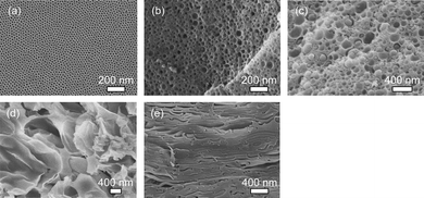
Firstly, the optimum compositional ratios of block copolymer and inorganic species (TEOS) were investigated. The weight ratios of TEOS to block copolymer were varied from 0.8 to 10. SAXS pattern for the film with high TEOS content (compositional ratio of TEOS to block copolymer is 10) showed the most intense several peaks derived from well-ordered close-packing of the mesopores (Fig. S1†). However, with the decrease of the added amount of TEOS, the ordering of the mesostructure was gradually decreased (Fig. S1†). From the scanning electron microscope (SEM) images of the calcined films prepared under various compositional ratios, it was observed that the mesopore sizes expanded gradually and their size distribution became broad (Fig. 1). At the lowest amount of the TEOS, the extra-large mesopores were formed, and then completely collapsed after the template removal, due to the lack of silica content in the framework (Fig. 1). Therefore, the optimum weight ratio of TEOS to block copolymer was 10 for the retention of well-ordered close packing of the mesopores.
 | ||
| Fig. 1 Cross-sectional SEM images of mesoporous silica films prepared from (a) Solution A, (b) Solution B, (c) Solution C, (d) Solution D, and (e) Solution E, respectively. The weight ratios of TEOS of block copolymer are 10 (Solution A), 6.6 (Solution B), 3.4 (Solution C), 1.6 (Solution D), and 0.8 (Solution E), respectively. | ||
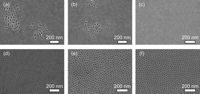
By using the above optimum compositions, mesoporous silica films were prepared at various speeds (from 1 mm s−1 to 20 µm s−1). The top-surfaces of the calcined films prepared at various coating speeds were examined by SEM observation (Fig. 2). When the substrate was pulled up at higher speed (over 500 µm s−1), the mesopores were randomly dispersed though their sizes were uniform (20 nm in diameter) (Fig. 2a and b). In some parts, larger voids were generated. With the decrease of dip-coating speeds, mesopores tended to be assembled and any voids were not observed (Fig. 2c and d). Interestingly, when the dip-coating speed was less than 50 µm s−1, the closely packed mesopores were realised (Fig. 2e and f). The close packing of the mesopores was observable at the inner parts of films (Fig. S2†).
 | ||
| Fig. 2 Top-surface SEM images of the calcined mesoporous silica films prepared by different dip-coating speeds: (a) 1 mm s−1, (b) 500 µm s−1, (c) 200 µm s−1, (d) 100 µm s−1, (e) 50 µm s−1, and (f) 20 µm s−1. | ||
On the basis of the above SEM results, we consider that such a drastic enhancement of the mesopore density on the film surface was strongly affected by an anisotropic convective flow of solution from bulk solution to meniscus which was induced by the evaporation of solution at the meniscus edge during the dip-coating process.12 Generally, the slow convective flow at the meniscus edge is quiet effective for alignment controls of nanoscale materials such as supermolecules and colloidal spheres. For example, it was previously reported that colloidal spheres were very closely packed by slow dip-coating (0.2 µm s−1).13 On the basis of the previous research background, we can imply the following possibility. At meniscus region, the self-assembly of the PS-b-PEO molecules is carried out due to easy solvent evaporation, forming the spherical micelles. Then, spherical micelles are brought to the meniscus edges to form closely packed mesopores in the films during the dip-coating. In the previous reports on mesoporous silica films using P123 and F127 (with relatively smaller molecular sizes), the coating speeds do not largely affect the mesostructural ordering and the packing degree of the mesopores.14 However, large size micelles consisting block copolymers are very sensitive to the dip-coating speeds.
To demonstrate the versatility of our concept, mesoporous niobia (Nb2O5) thin film with close-packing of mesopores was prepared by the optimum amount of the inorganic species and dip-coating speed (50 µm s−1). The experimental details were described in ESI†.
The SEM images of the obtained films were summarized in Fig. 3. In the film calcined at 500 °C (Fig. 3a and b), closely packed mesoporous structure like the silica case was obtained successfully. In the wide-angle XRD pattern, several peaks matching with the pseudohexagonal phase (TT-phase) were observed, revealing that the frameworks were well crystallised (Fig. S3†). Niobia is known to have several crystal structures depending on the calcination temperatures.15 When the calcination temperature reached to 600 °C, the second crystallization is occurred. Indeed, the wide-angle XRD pattern was attributed to the orthorhombic phase (T-phase) (Fig. S3†). On the top surface of the film, large grains started to appear (Fig. 3c). These grains were attributed to the increment of crystallite size due to the phase transition. Although the arrangement of the mesopores was distorted, mesoscale porosity was still remained.
 | ||
| Fig. 3 Top-surface SEM images of the mesoporous niobia films calcined at (a and b) 500 °C and (c) 600 °C, respectively. (b) is a bird-eye view of the accidentally cracked area. | ||
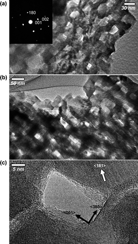
To investigate the mesoporous structure in detail, TEM images and the corresponding electron diffraction (ED) patterns were taken. The film calcined at 500 °C possessed spherical mesopores with a 20 nm diameter which is the same size as the silica system (Fig. S4†). The selected ED patterns showed several intense spots which were assigned to be a TT-phase (a, b = 3.607, c = 3.925 Å). The lattice fringes were coherently extended across over the mesopores, and randomly oriented over the entire area. Surprisingly, after calcination at 600 °C, the spherical mesopores in the film were changed to the cuboid shape, forming the mosaic-like porous structure (Fig. 4 and S5†). The selected-area ED patterns, which were taken with the incident electron beam parallel along the long axis of the cuboids, showed very intense spots (Fig. 4a), which were completely indexed to a single crystal T-phase (a = 6.168, b = 29.312, c = 3.936 Å). This is the evidence that the single crystal nature continuously was extended across over cuboid-shaped mesopores. The domain size of the single crystals was estimated to be over 500 nm2.
 | ||
| Fig. 4 TEM images of mesoporous niobia thin films after calcination at 600 °C (with an orthorhombic T-phase). TEM images with the incident electron beam (a) parallel and (b) perpendicular to the long axis of the cuboid shaped mesopores. The inset image indicates the ED patterns of the observed area in (a). | ||
Such a unique mesopore growth can be explained by a “surface-energy-induced mass-transportation phenomenon”.16 In general, low index surfaces of crystals tend to be preferably exposed on the external surface during crystallization process (or rearrangement process of atoms), because lower index surfaces have good thermal stability compared to higher index surfaces. Actually, from a highly magnified TEM observation, it was confirmed that the 001 facet surfaces (one of low index facets) were preferably exposed on the cuboid-shaped mesopores (Fig. 4c and S6†). The mesopores displayed in Fig. 4c were surrounded by two different crystal domains. The 001 facet surface was exposed together with 380 facet surface.
At the early stage of the crystallization process to T-phase, very high thermal energy was applied and the original spherical morphology of the mesopores could not retained. Then, several mesopores were merged due to the crystal growth of the frameworks.17 At this stage, however, the amount of Nb2O5 is insufficient to completely fill the mesopore space. Therefore, lots of voids (or defects) were generated in the films, which is the formation of the cuboid-shaped mesopores. During the formation of the voids, the low index surface with good thermal stability would be preferably exposed on the outer surface and then the crystal growth on that surface tends to decelerate. At the same time, other thermally stable surfaces (e.g., 380) which are oriented perpendicular to the 001 surface would be also exposed, which might be driven by the fact that the unit cell of the T-phase is cuboid shapes.16 When much larger thermal energy (longer calcination treatments or higher calcination temperature) is applied, the rapid mass transportation from high index onto low index surfaces further accelerates to prepare bulk T-phase crystal without mesoporosity. Tuning the applied thermal energy is vital for retention of mesopores and controls of the crystal structures. The above mechanism is the most reliable at present, although the details are still unclear.
In conclusion, we prepared mesoporous silica films with large mesopores by using PS-b-PEO type diblock copolymers. We found out that the micellar assembly on substrates was controlled by changing dip-coating speeds, for the first time. The distribution and density of the mesopores were manipulated. This paper provides the platform for making mesoporous films using block copolymers and our finding is widely applicable to various compositions.
Notes and references
- H. Yang, A. Kuperman, N. Coombs, S. Mamiche-Afara and G. A. Ozin, Nature, 1996, 379, 703 CrossRef CAS.
- I. A. Aksay, M. Trau, S. Manne, I. Honma, N. Yao, L. Zhou, P. Fenter, P. M. Eisenberger and S. M. Gruner, Science, 1996, 273, 892 CrossRef CAS.
- M. Ogawa, J. Am. Chem. Soc., 1994, 116, 7941 CrossRef CAS.
- D. A. Doshi, A. Gibaud, V. Goletto, M. Lu, H. Gerung, B. Ocko, S. M. Han and C. J. Brinker, J. Am. Chem. Soc., 2003, 125, 11646 CrossRef CAS.
- (a) T. Kondo, K. Nishio and H. Masuda, Jpn. J. Appl. Phys., 2010, 49, 025002 CrossRef; (b) T. Kondo, K. Nishio and H. Masuda, Chem. Lett., 2010, 39, 238 CrossRef CAS; (c) T. Yanagishita, R. Fujimura, K. Nishio and H. Masuda, Chem. Lett., 2010, 39, 188 CrossRef CAS; (d) M. Harada, T. Kondo, T. Yanagishita, K. Nishio and H. Masuda, Appl. Phys. Express, 2010, 3, 015001 Search PubMed; (e) T. Yanagishita, T. Endo, Y. Yamaguchi, K. Nishio and H. Masuda, Chem. Lett., 2009, 38, 274 CrossRef CAS; (f) T. Yanagishita, K. Nishio and H. Masuda, Appl. Phys. Express, 2009, 2, 022001 Search PubMed; (g) T. Kondo, K. Nishio and H. Masuda, Appl. Phys. Express, 2009, 2, 032001 Search PubMed.
- D. Zhao, P. Yang, N. Melosh, J. Feng, B. F. Chmelka and G. D. Stucky, Adv. Mater., 1998, 10, 1380 CrossRef CAS.
- C. Wu, Y. Yamauchi, T. Ohsuna and K. Kuroda, J. Mater. Chem., 2006, 16, 3091 RSC.
- X. Zhou, S. Qiao, N. Hao, X. Wang, C. Yu, L. Wang, D. Zhao and G. Q. Lu, Chem. Mater., 2007, 19, 1870 CrossRef CAS.
- (a) T. Brezesinski, A. Fischer, K. Iimura, C. Sanchez, D. Grosso, M. Antonietti and B. M. Smarsly, Adv. Funct. Mater., 2006, 16, 1433 CrossRef CAS; (b) D. Fattakhova-Rohlfing, M. Wark, T. Brezesinski, B. M. Smarsly and J. Rathouský, Adv. Funct. Mater., 2007, 17, 123 CrossRef CAS.
- M. Templin, A. Franck, A. D. Chesne, H. Leist, Y. Zhang, R. Ulrich, V. Schädler and U. Wiesner, Science, 1997, 278, 1795 CrossRef CAS.
- (a) Y. Deng, T. Yu, Y. Wan, Y. Shi, Y. Meng, D. Gu, L. Zhang, Y. Huang, C. Liu, X. Wu and D. Zhao, J. Am. Chem. Soc., 2007, 129, 1690 CrossRef CAS; (b) Y. Deng, J. Liu, C. Liu, D. Gu, Z. Sun, J. Wei, J. Zhang, L. Zhang, B. Tu and D. Zhao, Chem. Mater., 2008, 20, 7281 CrossRef CAS.
- (a) A. S. Dimitrov and K. Nagayama, Langmuir, 1996, 12, 1303 CrossRef CAS; (b) B. G. Prevo and O. D. Velev, Langmuir, 2004, 20, 2099 CrossRef CAS; (c) M. H. Kim, S. H. Im and O. O. Park, Adv. Funct. Mater., 2005, 15, 1329 CrossRef CAS; (d) B. G. Jung, S. H. Min, C. W. Kwon, S. H. Park, K. B. Kim and T. S. Yoon, J. Electrochem. Soc., 2009, 156, K86 CrossRef CAS.
- Z. Z. Gu, A. Fujishima and O. Sato, Chem. Mater., 2002, 14, 760 CrossRef.
- (a) S. P. Naik, S. Yamakita, M. Ogura and T. Okubo, Microporous Mesoporous Mater., 2004, 75, 51 CrossRef CAS; (b) S. P. Naik, S. Yamakita, Y. Sasaki, M. Ogura and T. Okubo, Chem. Lett., 2004, 33, 1078 CrossRef CAS.
- (a) H. Schäfer, R. Gruehn and F. Schulte, Angew. Chem., 1966, 78, 28 CrossRef; (b) K. Kato and S. Tamura, Acta Crystallogr., Sect. B: Struct. Crystallogr. Cryst. Chem., 1975, 31, 673 CrossRef; (c) L. K. Frevel and H. W. Rinn, Anal. Chem., 1955, 27, 1329 CrossRef CAS.
- Z. L. Liau and H. J. Zeiger, J. Appl. Phys., 1990, 67, 2434 CrossRef CAS.
- (a) J. N. Kondo and K. Domen, Chem. Mater., 2008, 20, 835 CrossRef CAS; (b) B. Lee, D. Lu, J. N. Kondo and K. Domen, Chem. Commun., 2001, 2118 RSC.
Footnote |
| † Electronic supplementary information (ESI) available: Experimental details and additional characterization data. See DOI: 10.1039/c0ce00507j |
| This journal is © The Royal Society of Chemistry 2011 |
