Photoinduced hyper-reflective cholesteric liquid crystals enabled via surface initiated photopolymerization†‡
Michael E.
McConney
,
Vincent P.
Tondiglia
,
Jennifer M.
Hurtubise
,
Timothy J.
White
and
Timothy J.
Bunning
*
Materials and Manufacturing Directorate, Air Force Research Laboratory, 3005 Hobson Way, WPAFB, OH, USA. E-mail: timothy.bunning@wpafb.af.mil; Fax: +1 937-255-1128; Tel: +1 937-255-9649
First published on 25th October 2010
Abstract
A structured polymer was synthesized by surface initiated photopolymerization in the presence of a cholesteric liquid crystal (CLC). The templated helical polymer (traversing 2/3 the cell thickness) was backfilled with an opposite handedness, photoresponsive CLC mixture yielding a photo-induced, large contrast, hyper-reflective (R > 99%) CLC film.
Cholesteric liquid crystals (CLCs) are well-known to exhibit selective reflection of incident radiation making them promising in a myriad of different photonic applications. The reflection is caused by the macroscopic helical structure of the director, where the central wavelength of the Bragg reflection is given by λB =
![[n with combining macron]](https://www.rsc.org/images/entities/i_char_006e_0304.gif) P, where P is the pitch length of the helical twist of the director and is the average refractive index defined as = (ne + no)/2. The pitch is typically controlled by chiral dopant concentration (P = 1/(HTP × c)) where c is the concentration of the chiral dopant and HTP is the helical twisting power of the chiral dopant. The Bragg reflection of incident unpolarized light is circularly polarized (CPL), matching the handedness of the helical structure of the CLC. Thus, a single CLC film is limited to reflecting no more than 50% of incident unpolarized light.
P, where P is the pitch length of the helical twist of the director and is the average refractive index defined as = (ne + no)/2. The pitch is typically controlled by chiral dopant concentration (P = 1/(HTP × c)) where c is the concentration of the chiral dopant and HTP is the helical twisting power of the chiral dopant. The Bragg reflection of incident unpolarized light is circularly polarized (CPL), matching the handedness of the helical structure of the CLC. Thus, a single CLC film is limited to reflecting no more than 50% of incident unpolarized light.
Higher contrast reflectivity (>50%) is needed in a number of applications where a large reflectivity or a minimum in transmission at a specified wavelength is desired when employing unpolarized radiation. The most common approach to achieve high contrast is to stack two individual CLC cells, each with opposite handedness.1,2 Another approach employs a half-wave plate sandwiched between separate CLC thin films of the same handedness. Nature utilizes this approach in the golden scarab beetle, which has also been realized in engineered systems.1,3 Although effective in realizing higher contrast devices, these approaches have a number of drawbacks including increased weight, complicated electrical designs, and increased insertion loss (Fresnel and scattering) due to the large number of interfaces.
The ability to form a ‘hyper-reflective’ CLC, i.e. a device that reflects both right- and left-handed (RH and LH) circularly polarized light simultaneously from a single film, would overcome a number of these drawbacks.
The simple mixing of chiral dopants of opposite handedness results in a compensated nematic phase4–6 as the dopants cancel each other out. However, recent reports have started to document methods of going beyond the 50% reflectance limit in a single CLC geometry (hyper-reflectivity) through the use of polymer stabilization and scaffolding. Chirally structured materials are not limited by the rule of mixtures and thus offer a route to circumvent this issue.7
Mitov created hyper-reflective CLCs by polymerizing a monomer in the presence of a thermal inverter at elevated temperature, 120 °C. After creating a polymer network with a RH helical structure, the mixture was cooled to 60 °C, a temperature at which the thermal inverter returned to LH.8–10 Despite the LH nature of the CLC mixture at 60 °C, the polymer network imparts its RH helicity to a fraction of the LC near the polymer surface. Guo et al. also employed polymer stabilization to create a hyper-reflective system. Using a multi-step “wash-out/refill” procedure involving polymerization in the presence of a RH CLC, leaching of the CLC mixture (leaving the polymer scaffold), and subsequent refilling of the cell with a LH CLC.11 One advantage of this approach is that the scaffold can be backfilled with any LC or non-LC mixture.11,12 Both of these approaches take advantage of local differences in handedness across the x, y plane of a CLC film where the axis of the pitch is in the z-direction. Incident light is spatially impingent on regions of both handedness resulting in hyper-reflective CLCs that exhibit >50% reflection at a fixed wavelength.
In the work presented here, photopolymerization of a templated helical polymer structure (from one side of cell) is used to subsequently realize hyper-reflective CLCs wherein a spatial segregation of the LH and RH domains occurs in the z-direction (through the thickness of the cell). Moreover, we extend this concept to demonstrate a dynamically induced hyper-reflective cell using photosensitive LCs for the first time.
Shown in Fig. 1A–D is a schematic representation of the fabrication procedure used to create the surface tethered polymer scaffold with the associated transmission spectra for each fabrication step. Cells were fabricated using the typical procedure with the distinct difference that one of the anchoring layers was formed by spin-coating a polyimide solution that contained 1% photoinitiator. By embedding the photoinitiator into the anchoring layer of only one of the substrates, polymerization occurs from only one side of the cell. These cells were subsequently filled with a (RH) CLC mixture containing an achiral nematic LC (E7), a RH chiral dopant (R811), an achiral diacrylate monomer (RM257) and a RH chiral monomer (RM691) (see ESI‡ for details) which before polymerization exhibits a Bragg reflection of approximately 720 nm (Fig. 1A). Although not a focus of this paper, slight changes to the original bandwidth and notch position occur upon polymerization (Fig. 1B).
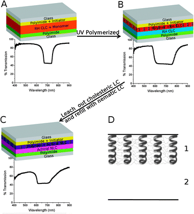 | ||
| Fig. 1 (A–C) Schematic representation of the fabrication process with transmission spectra of cell during each respective step. (D) Simple schematic showing that the cells have 2 distinct regions which are separated across the z-direction (thickness). | ||
After polymerization, the LC mixture and unpolymerized monomer was leeched from the cell by immersing in cyclohexane for several days followed by vacuum oven drying. Refilling the cell with the nematic LC E7 returns the reflection notch to 670 nm (see Fig. 1C). This confirms the polymer scaffold is helical (still RH) and maintains the original pitch of the post-polymerized CLC after the leeching/refilling process. The reflection observed in Fig. 1C is induced via structural chirality imposed by the chiral polymer network, as opposed to induction via chiral dopants. A simple schematic is shown in Fig. 1D to illustrate that the cell possesses two distinct regions (for a 30 μm thick cell, the thickness of the polymer was measured to be 19 ± 2 μm). Region 1 possesses the RH helical polymer scaffold whereas region 2 is empty. Upon backfilling the cell, region 1 imparts its chiral handedness onto the mixture forming a RH notch at ∼670 nm whereas region 2 maintains the characteristics of the filling agent. As shown in this work, the helical polymer scaffold allows for the possibility of backfilling with numerous materials including nematic LC (Fig. 1C), opposite handedness CLCs (Fig. 2 and 3), or a photoresponsive opposite handedness CLC (Fig. 4).
 | ||
| Fig. 2 A cell with a templated helical polymer is backfilled with a LH CLC mixture (20% S811/E7). In the unpolarized transmission spectra, two reflection notches are evident at 700 nm and 900 nm. As evident in the inset circularly polarized spectra, the reflection of the 900 nm notch is LH (from the S811/E7 mixture) while the reflection of the 700 nm notch is RH and is due to the RH polymer scaffold. | ||
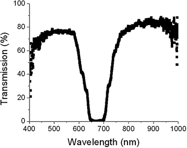 | ||
| Fig. 3 Transmission spectrum of a cell in which the reflection wavelength of the LH notch of the bulk CLC matches the RH notch wavelength from the polymer templated CLC. | ||
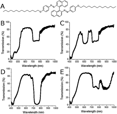 | ||
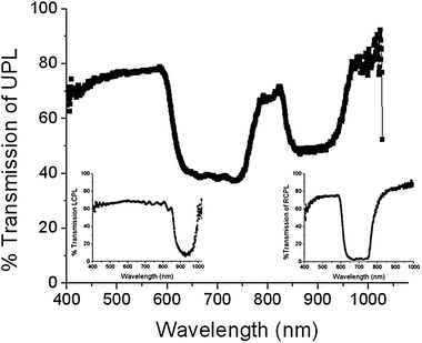
| Fig. 4 (A) Azo-based photosensitive chiral dopant QL-76. (B–E) Transmission spectra of the cell filled with photo-tunable mixture after different UV exposure times. (B) 0 seconds, (C) 46 seconds, (D) 138 seconds and (E) 293 seconds. | ||
Fig. 2 demonstrates that upon backfilling with a LH CLC mixture (20% S811 + 80% E7), a cell which exhibits reflection of both polarization handedness is formed. Two reflection notches, offset in wavelength are observed at 690 nm and 900 nm. The insets, circularly polarized transmission spectrum from the cell, confirm that one of these reflections is RH (from region 1 in Fig. 1D) while the other is LH (from region 2). The LH reflection matches the spectrum of the original S811 (20%)/E7 mixture. The observation of a RH reflection notch indicates that the helical polymer template overpowers the nascent LH preference of the S811/E7 CLC mixture. Backfilling with a LH mixture that matches the RH template then yields a static hyper-reflective CLC cell as shown in Fig. 3. The distinct presence of both handedness domains segregated across the thickness of the cell gives rise to high contrast (>99% reflectivity) from a single cell geometry.
We extend this methodology to the fabrication of a dynamically induced hyper-reflective CLC, wherein the contrast can be modulated by introducing variability into the system that is present in region 2 (Fig. 1D). A templated cell was backfilled with a LH CLC mixture formulated with a photosensitive chiral dopant, QL-76 (Fig. 4A).13,14 Photosensitive molecules are an increasingly popular approach to create color tunable CLCs.15 Light-induced color changes can be enabled through the utilization of photosensitive mixtures with photo-variable HTPs or photo-variable LC ordering properties. The net result in both cases is that upon exposure to light (typically UV), changes in the selective reflection properties can be induced.
CLC mixtures based on QL-76 have been shown to exhibit large Bragg reflection wavelength tuning due to a UV-induced change in HTP from 60 μm−1 to 27 μm−1 as the molecule is driven from a trans/trans isomer to a cis/cis isomer.13,14 The net result is a large red-shift in the reflection wavelength (which is reversible upon exposure to green light). A photoresponsive cell was created by backfilling a templated RH cell with a LH mixture of 8% by weight of QL-76 to 1444.
Initially (Fig. 4B), the left-handed reflection notch of the LH QL-76/1444 mixture is almost completely overlapped with the azo absorption band around 450 nm whereas the RH notch due to the templated region is observed at ∼750 nm. Exposing the cell for 46 s to 450 μW cm−2 of 362 nm radiation red shifts the selective reflection band (LH) out of this absorption band to ∼600 nm (Fig. 4C). Additional UV-light exposure (total of 138 s) further red-shifts the LH notch of the photosensitive CLC to 750 nm where it overlaps spectrally with the RH notch formed by the polymer scaffold templated CLC. In this state, a reflectivity approaching 99% is achieved from the single cell architecture. Further UV-exposure drives the LH CLC reflection wavelength past 900 nm. The reflectivity of the single cell varies from the normal 50% to greater than 98% in the hyper-reflective condition to back to 50% when the LH notch has red-shifted off the static RH notch. After red-tuning the LH mixture past 1000 nm, the UV-light was removed. The cell was exposed to green light (532 nm) which blue-shifted the reflection notch back until the notches overlapped again (see ESI‡). A video of the photoresponsiveness of this material system is provided in the ESI.‡
Using anisotropic surface polymerization (one side only), a helical polymer structure tethered to only one of the substrates and traversing less than 2/3 of the cell gap was formed. This as-polymerized structure exhibits a RH structure and was shown to template a wide variety of materials upon cell draining and re-filling, all realizing a RH reflection notch at the pre-drained wavelength. Backfilling of this cell with LH CLC material results in segregation through the thickness of the cell of separate RH and LH regions, each reflecting its own handedness radiation. This technique was used to demonstrate a hyper-reflective CLC film wherein high contrast (R > 99%) reflectivity was observed in a single CLC cell when the pitch of each region was matched. Moreover, using a photosensitive LC mixture, a dynamically induced hyper-reflective CLC system was formed where UV light could be used to vary the high contrast reflective properties.
The authors would like to express their gratitude to Prof. Q. Li from Kent State University for providing the photosensitive chiral dopant and Dr L. Natarajan (SAIC) for useful discussions. This work was supported by AFOSR and AFRL. MEM gratefully acknowledges the National Research Council for fellowship support.
Notes and references
- D. M. Makow, Appl. Opt., 1980, 19, 1274–1277 CrossRef CAS.
- M. H. Song, N. Y. Ha, K. Amemiya, B. Park, Y. Takanishi, K. Ishikawa, J. W. Wu, S. Nishimura, T. Toyooka and H. Takezoe, Adv. Mater., 2006, 18, 193–197 CrossRef CAS.
- S. Caveney, Proc. R. Soc. London, Ser. B, 1971, 178, 205–225 CrossRef CAS.
- S. Kurihara, S. Nomiyama and T. Nonaka, Chem. Mater., 2000, 12, 9–12 CrossRef CAS.
- B. L. Feringa, N. P. M. Huck and H. A. van Doren, J. Am. Chem. Soc., 1995, 117, 9929–9930 CrossRef CAS.
- M. Zhang and G. B. Schuster, J. Phys. Chem., 1992, 96, 3063–3067 CrossRef CAS.
- K. Robbie, D. J. Broer and M. J. Brett, Nature, 1999, 399, 764–766 CrossRef CAS.
- M. Mitov and N. Dessaud, Nat. Mater., 2006, 5, 361–364 CrossRef CAS.
- M. Mitov and N. Dessaud, Liq. Cryst., 2007, 34, 183–193 CrossRef CAS.
- A. C. Tasolamprou, M. Mitov, D. C. Zografopoulos and E. E. Kriezis, Opt. Commun., 2009, 282, 903–907 CrossRef CAS.
- J. Guo, H. Cao, J. Wei, D. Zhang, F. Liu, G. Pan, D. Zhao, W. He and H. Yang, Appl. Phys. Lett., 2008, 93, 201901 CrossRef.
- S. S. Choi, S. M. Morris, W. T. S. Huck and H. J. Coles, Adv. Mater., 2010, 22, 53–56 CrossRef CAS.
- Q. Li, L. Green, N. Venkataraman, I. Shiyanovskaya, A. Khan, A. Urbas and J. W. Doane, J. Am. Chem. Soc., 2007, 129, 12908–12909 CrossRef CAS.
- T. J. White, R. L. Bricker, L. V. Natarajan, N. V. Tabiryan, L. Green, Q. Li and T. J. Bunning, Adv. Funct. Mater., 2009, 19, 3484–3488 CrossRef CAS.
- T. J. White, M. E. McConney and T. J. White, J. Mater. Chem., 2010 10.1039/c0jm00843e.
Footnotes |
| † This article is part of the ‘Emerging Investigators’ themed issue for ChemComm. |
| ‡ Electronic supplementary information (ESI) available: Materials, methods, and additional characterization, including a tuning video. See DOI: 10.1039/c0cc02215b |
| This journal is © The Royal Society of Chemistry 2011 |