Silicon as a potential anode material for Li-ion batteries: where size, geometry and structure matter
Maziar
Ashuri
ab,
Qianran
He
ab and
Leon L.
Shaw
*ab
aDepartment of Mechanical, Materials and Aerospace Engineering, Illinois Institute of Technology, Chicago, IL, USA. E-mail: lshaw2@iit.edu
bWanger Institute for Sustainable Energy Research (WISER), Illinois Institute of Technology, Chicago, IL, USA
First published on 13th November 2015
Abstract
Silicon has attracted huge attention in the last decade because it has a theoretical capacity ∼10 times that of graphite. However, the practical application of Si is hindered by three major challenges: large volume expansion during cycling (∼300%), low electrical conductivity, and instability of the SEI layer caused by repeated volume changes of the Si material. Significant research efforts have been devoted to addressing these challenges, and significant breakthroughs have been made particularly in the last two years (2014 and 2015). In this review, we have focused on the principles of Si material design, novel synthesis methods to achieve such structural designs, and the synthesis–structure–performance relationships to enhance the properties of Si anodes. To provide a systematic overview of the Si material design strategies, we have grouped the design strategies into several categories: (i) particle-based structures (containing nanoparticles, solid core–shell structures, hollow core–shell structures, and yolk–shell structures), (ii) porous Si designs, (iii) nanowires, nanotubes and nanofibers, (iv) Si-based composites, and (v) unusual designs. Finally, our personal perspectives on outlook are offered with an aim to stimulate further discussion and ideas on the rational design of durable and high performance Si anodes for the next generation Li-ion batteries in the near future.
I. Introduction
Li ion batteries (LIBs) have revolutionized portable electronic devices in the past two decades, and have the potential to make a great impact on vehicle electrification.1 In spite of their eminent potential, the state-of-the-art Li-ion batteries (such as LiCoO2/graphite batteries) have not been able to meet the requirements for vehicle electrification, requiring both high energy density and high power density with a long cycle life simultaneously.2 Therefore, batteries with high energy density, high power density and long cycle life are in urgent demand to address the driving distance problem faced by LIBs. In this context, silicon is one of the most promising anode candidates for the next-generation Li-ion batteries. This is due to its low voltage profile and high theoretical capacity (3590 mA h g−1 for the Li15Si4 phase at room temperature),3 which is about ten times that of carbonaceous materials including graphite, pyrolytic carbon and meso-phase pitch (about 372 mA h g−1). In addition, silicon is the second ample element in the earth's crust. Therefore, mass production of silicon at low cost is not an issue. However, practical application of silicon anodes is currently hindered by multiple challenges including the enormous volume change (∼300%) during lithiation/delithiation processes, low intrinsic electrical conductivity, and instability of the solid electrolyte interface (SEI).4,5 The large volume change can result in particle pulverization, loss of electrical contact with the conductive additive or the current collector, and even peeling off from the current collector. The repeated volume expansion and shrinkage also lead to fracture and re-formation of the SEI layer around the particles, resulting in continuous consumption of the electrolyte, an increased impedance, and capacity fading.4–10Significant efforts have been devoted to addressing the issues mentioned above. The strategies investigated include Si material design through nanostructures,11–15 porous structures,16–19 or nanocomposites,20–22 Si electrode design with combined nano- and micro-particles23 or with 3D micro-channels,24 addition of electrolyte additives,25 and the use of novel binders.26,27 Thanks to the worldwide efforts, rapid advancements have been made in the properties and performance of Si anodes. These rapid advances have been reflected in a large number of review articles published recently.2,8–10,28–39 In fact, just in 2014 alone there are 6 review articles on Si anodes,8,32–36 clearly indicating rapid expansion of research and advancements in the area of Si anodes. In spite of these outstanding reviews,2,8–10,28–39 it is warranted that another review is due because significant advancements and breakthroughs have been made in 2014 and 2015. Examples of such breakthroughs include exceptional specific and volumetric capacities at 1160 mA h g−1 and 1270 mA h cm−3, respectively, after 1000 cycles at the C/2 rate accomplished through a pomegranate-inspired nanoscale design,15 high specific and volumetric capacities at 1600 mA h g−1 and 1088 mA h cm−3, respectively, after 150 cycles at 400 mA g−1 achieved via a micro-sized porous Si/C material,18 and a specific capacity of 1450 and 1230 mA h g−1 after 100 cycles at 100 and 500 mA g−1, respectively, obtained via a low cost, double-shelled Si@SiOx@C core–shell structure.40 However, none of these breakthroughs are included in the 2014 reviews.8,32–35 Only one article published in 201441 is cited in these 2014 reviews. In contrast, in this review we have selected more than 25 articles5,13,15,18–22,24,40–55 published in 2014 and 2015 to highlight the new strategies and advancements made in the area of Si anodes. Furthermore, by integrating these 25+ articles with many previous publications, we have provided a comprehensive overview on strategies in the Si material design, novel synthesis methods, and the synthesis–structure–performance relationships to enhance the properties and performance of Si anodes, as outlined below.
In this review, we will start with an overview of the intrinsic properties of Si, followed by various strategies investigated so far to overcome the shortcomings of Si anodes. These strategies are grouped as follows: (i) particle-based structures (including nanoparticles, solid core–shell structures, hollow core–shell structures, and yolk–shell structures), (ii) porous Si designs, (iii) nanowires, nanotubes and nanofibers, (iv) Si-based composites, and (v) unusual designs. Finally, our personal perspectives on outlook are offered with an aim to stimulate further discussion and ideas on the rational design of durable and high performance Si anodes for the next generation Li-ion batteries in the near future.
II. Intrinsic properties of silicon
Si has a theoretical capacity of 3590 mA h g−1 based on the fully alloyed form of Li15Si4 at room temperature,3 and this value increases to 4200 mA h g−1 at high temperature corresponding to the formation of Li22Si5.56 These capacities place Si on the top of all other anode materials except Li. As shown in Table 1,57 Si not only has the highest specific capacity, but also has the highest volumetric capacity among all the common anode materials investigated except pure Li metal.| Materials | Li | C | Li4Ti5O12 | Si | Ge | Sn |
|---|---|---|---|---|---|---|
| Notes: (1) Theoretical volumetric capacity = Theoretical specific capacity × Density. (2) Volume change (%) = (Volume of lithiated phase/Volume of delithiated phase − 1) × 100. | ||||||
| Density (g cm−3) | 0.53 | 2.25 | 3.5 | 2.3 | 5.3 | 7.3 |
| Lithiated phase | Li | LiC6 | Li7Ti5O12 | Li4.4Si | Li4.4Ge | Li4.4Sn |
| Density of lithiated phase (g cm−3) | 0.53 | 2.20 | 3.65 | 1.18 | 2.04 | 2.56 |
| ICDD PDF card number | (00-001-1131) | (00-034-1320) | (00-049-0207) | (01-077-2882) | (00-017-0402) | (00-018-0753) |
| Theoretical specific capacity in the delithiated state (mA h g−1) | ∞ | 372 | 175 | 4200 | 1620 | 993 |
| Theoretical specific capacity in the lithiated state (mA h g−1) | 3860 | 339 | 168 | 2010 | 1140 | 790 |
| Theoretical volumetric capacity in the delithiated state (mA h cm−3) | ∞ | 837 | 613 | 9660 | 8600 | 7250 |
| Theoretical volumetric capacity in the lithiated state (mA h cm−3) | 2050 | 747 | 614 | 2370 | 2330 | 2020 |
| Volume change (%) | ∞ | 12 | 1 | 410 | 370 | 260 |
| Potential versus Li/Li+ (V) | 0 | 0.05 | 1.6 | 0.4 | 0.5 | 0.6 |
Fig. 1 shows the typical charge and discharge profiles of crystalline silicon.3 The first lithiation (I region in Fig. 1) leads to the formation of an amorphous phase. If the lithiation is continuous below 50 mV (II region), crystalline Li15Si4 will form. The subsequent delithiation (III region) results in amorphous Si which then becomes an amorphous LixSi alloy in the following lithiation (IV region). Therefore, after the first charge/discharge cycle crystalline silicon has converted to amorphous and remains amorphous in further cycles.3,58Fig. 1 also shows that Si anodes can provide a very attractive working potential (∼0.4 V vs. Li/Li+), which is slightly higher than that of graphite anodes (∼0.05 V vs. Li/Li+) but can avoid the safety concern of lithium deposition upon cell overcharge.
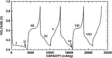 | ||
| Fig. 1 Charge/discharge voltage profile of micro-sized Si. Reproduced with permission.3 © 2006, The Electrochemical Society. | ||
The formation of the Li15Si4 phase leads to a large volume expansion (∼300%).3,15,34 The repeated volume expansion and shrinkage associated with lithiation and delithiation, respectively, can result in particle pulverization and loss of electrical contact with the conductive additive or the current collector.5–10 The repeated volume expansion and shrinkage also led to fracture and re-formation of the SEI layer around the particles, resulting in continuous consumption of the electrolyte, increased impedance, and capacity fading.4 It has been shown that volume expansion is anisotropic for crystalline Si,48,59 but becomes homogeneous for amorphous Si. Lithiation of crystalline Si is anisotropic too with the (110) surface being more thermodynamically favorable for lithiation than the (100) and (111) surfaces.48,60In situ TEM observations61,62 reveal that lithiation of crystalline Si particles occurs by the movement of a two-phase boundary between the inner core of pristine Si and the outer shell of amorphous Li–Si alloy. In situ TEM analysis of Si nanowires63 and SEM observations of Si nanopillars64 clearly show the anisotropic expansion of Si during lithiation. The anisotropic swelling of Si nanowires and nanopillars has been attributed to different interfacial energies of the amorphous Li–Si alloy and the crystalline Si interface and thus different interface mobilities.47,63 It should be emphasized that these anisotropic lithiation and swelling behaviors are only applicable to the first lithiation cycle because after the first lithiation the initially crystalline Si remains amorphous in the subsequent cycling.62
In situ TEM analysis has provided unambiguous evidence that a large volume expansion during lithiation can result in cracking of Si particles.61,62 These in situ TEM observations have revealed that there exists a critical particle diameter of ∼150 nm below which Si particles will not crack.61,62 However, it is interesting to note that an early study suggests that the critical size of Si particles without cracking is <20 nm.11 Regardless of the precise number of the critical particle size, these studies do highlight the important role of nanostructures to yield high capacities.65 Although nanoparticles do not crack, this feature alone is not sufficient because volume expansion and shrinkage still take place and can result in a gradual loss of electrical contact with the conductive additive or the current collector, leading to gradual capacity decay.5,40 As discussed below, nanostructures combined with other strategies often offer far better performance than nanoparticles alone.
A recent study66 using mechanically clamped Si pillars to mimic the cluster of many crystalline Si particles in the confined volume within an anode shows some beneficial effects of compressive stresses in suppressing crack formation during lithiation. Specifically, unclamped Si pillars have a critical diameter of ∼300 nm above which cracking always occurs. However, when a <110> axially oriented Si pillar of 1 μm in diameter expands during lithiation with a gap of 300 nm to the walls (which oppose the expansion of Si when the Si pillar is in contact with them), only a few pillars exhibit noticeable cracking. When the diameter of the same Si pillar increases to 2.2 μm still with a gap of 300 nm to the walls, significant cracking occurs. These results are interesting and important because they provide evidence that the critical size of Si pillars for cracking can be increased from ∼300 nm to larger than 1000 nm. This phenomenon is expected to be applicable to Si particles with a mechanically robust, conductive coating. The latter can serve two purposes: offering highways for electron and Li-ion transport while suppressing the crack formation.
Silicon is a semiconductor and thus high purity Si has a very low electrical conductivity at room temperature (<10−5 S cm−1). However, doped Si (both n-type and p-type Si) can have electrical conductivities of ∼10−2 S cm−1.67 These values are significantly lower than carbon and graphite which have electrical conductivity of the order of 10–104 S cm−1,68 but are comparable with or higher than several oxide electrode materials such as LiCoO2 (∼10−4 S cm−1), LiMn2O4 (∼10−6 S cm−1) and LiFePO4 (10−9 S cm−1).68 Thus, conductive additives or coatings are necessary for the fabrication of Si anodes.
III. Particle-based structures
Silicon in the particle morphology has been studied extensively. To facilitate discussion, we have classified Si particle-based structures into four categories (Fig. 2). The first group is nanoparticles including both solid and hollow particles (Fig. 2a). The second group is solid core–shell structures in which Si serves as a core and the shell is typically an electronic and ionic conductor (Fig. 2b). The third group is hollow core–shell structures in which the Si core is hollow (Fig. 2c), whereas the conductive shell is the same as the solid core–shell structure. The last group is yolk–shell structures (Fig. 2d), which have the void between the solid Si core and the outer conductive shell. These different particle structures respond to lithiation and delithiation differently, and thus have a strong impact on the electrochemical performance of Si anodes, as described below. | ||
| Fig. 2 Si particles with different internal architectures: (a) solid and hollow particles, (b) solid core–shell structures, (c) hollow core–shell structures, and (d) yolk–shell structures. | ||
3.1 Nanoparticles
Wang et al.40 have recently compared the cycling performance of micro-sized Si particles (1–2 μm) with those of nano-sized Si (∼0.15 μm) with and without carbon coating. Their study clearly indicates that the nano-sized Si has a higher specific capacity and better capacity retention than those of the micro-sized Si, whereas the carbon-coated, nano-sized Si has the best performance (Fig. 3). Specifically, the micro-sized Si possesses a specific capacity of 650 mA h g−1 after 100 cycles with a charge/discharge current of 100 mA g−1 and its capacity retention is only 20% when compared with the first charge capacity.40 In contrast, the nano-sized Si exhibits a capacity of 1060 mA h g−1 after 100 cycles with its capacity retention of 38%, whereas the carbon-coated, nano-sized Si, a-Si@SiOx/C (1/2.5), has the highest capacity (1450 mA h g−1) and capacity retention (73%) after 100 cycles.47 This set of data unambiguously reveals that capacity retention can be improved by reducing the particle size because of the reduced tendency for particle cracking and smaller volume change per particle during cycles. The carbon coating can further improve the capacity retention probably because of the buffering effect of the coating. However, such a buffering effect may not be present in every system, as discovered in the other studies discussed below.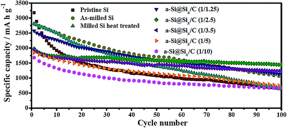 | ||
| Fig. 3 Cycling performance of amorphous Si@SiOx/C core–shell particles in comparison with micro-sized Si particles (pristine Si) and nano-sized Si@SiOx without carbon coating (as-milled Si). The SiOx layer is due to the oxidation of Si particles under an ambient atmosphere and thus is ultrathin, whereas the carbon coating is formed via carbonization of citric acid. The number in the parentheses after a-Si@SiOx/C represents the Si-to-citric acid ratio. Reproduced with permission.40 © 2014, Elsevier. | ||
Pan et al.5 have carried out another comparison of commercial Si nanoparticles (∼100 nm) with and without carbon coating, denoted as Si@C and Si, respectively, in Fig. 4. The carbon coating is formed by carbonization of polydopamine (PODA). The formed Si@C particles are then etched with a NaOH aqueous solution to obtain a yolk–shell structure, Si@void@C, which is included in Fig. 4 for comparison. It can be seen that Si nanoparticles have the highest initial specific capacity, but their capacity decays very fast. With the carbon coating (5–8 nm thick) the capacity decay slows down, but eventually the capacity of Si@C approaches that of Si nanoparticles after 50 cycles, indicating that the effect of the carbon coating is limited. In contrast, the Si@void@C yolk–shell structure exhibits superior capacity retention and still possesses 804 mA h g−1 after 50 cycles. The void in the yolk–shell structure provides space to accommodate volume expansion and shrinkage during cycles, whereas the carbon shell offers a stable interface for stability of the SEI layer and particle contacts between themselves and with the conductive additive and the current collector. Therefore, nanoparticles alone are not sufficient to have good capacity retention. Engineering the particle structure by introducing voids to accommodate volume expansion is a promising strategy to improve the capacity retention.
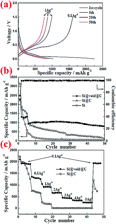 | ||
| Fig. 4 Electrochemical performance of commercial Si nanoparticles (∼100 nm) with and without carbon coating, denoted as Si@C and Si, respectively, in comparison with that of a yolk–shell structure, Si@void@C. Reproduced with permission.5 © 2014, The Royal Society of Chemistry. | ||
Another way to introduce void into the particle structure is to synthesize hollow Si particles, as demonstrated by Yao et al.69 The hollow Si particles are formed by a template approach using solid silica nanospheres (350 nm in diameter). The silica nanospheres are drop-cast on a stainless steel sheet and a thin layer of silicon is subsequently deposited on the nanospheres through chemical vapor deposition (CVD) of SiH4 at 485 °C. The thickness of this Si shell is about 10 nm. In the end, the silica core is removed by dilute HF solution, leading to Si hollow spheres. These Si hollow spheres are interconnected and offer an initial discharge capacity of 2725 mA h g−1 which survives 700 cycles with a capacity loss of 8% every 100 cycles (Fig. 5). The capacity retention is far better than that of solid nanoparticles because the void space in hollow Si spheres can accommodate volume expansion during lithiation and thus minimize the chance of crack forming in particles as well as reducing volume expansion outwards. The latter is important because little or no volume expansion outwards can lead to a stable SEI layer and good contact between particles and conductive additives.4
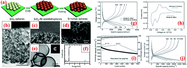 | ||
| Fig. 5 (a) Hollow silicon sphere formation process; (b–f) characterization data, and (g–j) electrochemical results. Reproduced with permission.69 © 2011, American Chemical Society. | ||
The study carried out by Kim et al.11 revealed that nanoscale particles (<20 nm) are needed to avoid particle cracking, but optimization of particle sizes is required to obtain high specific capacities and good capacity retention over cycles. As shown in Fig. 6, 5 nm Si nanoparticles have lower specific capacities than 10 nm and 20 nm Si nanoparticles in the entire range of 40 cycles investigated. Interestingly, the specific capacities of all nanoparticles degrade gradually over the 40 cycles. However, the capacity decay becomes extremely small when 10 nm Si nanoparticles are coated with a carbon shell via chemical vapor deposition of acetylene at 500 °C, indicating that confining the expansion of Si nanoparticles with a strong and conductive shell can greatly enhance the cycle stability.
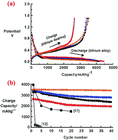 | ||
| Fig. 6 (a) Voltage profiles of 5, 10, and 20 nm sized n-Si and 10 nm sized n-Si after carbon coating during the first cycle in coin-type half-cells at a rate of 0.2C between 0 and 1.5 V. (b) Plot of charge capacity versus cycle number (red: 5 nm, blue: 10 nm, orange: 10 nm after the carbon coating, black circles: 20 nm). Reproduced with permission.11 © 2010, Wiley-VCH Verlag. | ||
3.2 Solid core–shell structures
The research discussed in section 3.1 has revealed that a solid Si core with a conductive shell could offer some advantages over bare Si particles without coating. However, the advantages are limited in some cases because a huge volume expansion of the Si core during lithiation still leads to volume expansion of the entire core–shell particle. This trend has been corroborated by several other studies, as discussed below. In addition, it can be reasoned that the mechanical properties of the conductive shell could play a critical role in suppressing or minimizing the volume expansion of the Si core, thereby leading to a more stable interface between particles and minimizing the fracture and re-formation of the SEI layer. Furthermore, the size of the Si core is also an important factor in dictating the cyclic stability since a small Si core results in small volume expansion. Motivated by these several possible mechanisms, different solid core–shell structures have been synthesized and studied.Hwa et al.70 have prepared a solid core–shell material with Si nanoparticles (<100 nm) as the core and amorphous carbon as the shell, denoted as n-Si@C hereafter. The process starts with a uniform coating of nano-sized Si particles with polyvinyl alcohol (PVA). The mixed powder is then centrifuged and dried at room temperature. The next step is calcination at 750 °C under an Ar atmosphere for 3 h. The carbon shell was amorphous with a thickness of about 5–10 nm (Fig. 7). To better evaluate the electrochemical performance of this solid core–shell nanomaterial, batteries with Si nanoparticles without coating (n-Si), micro-sized Si particles (4 μm) coated with carbon (Si@C), and nano-sized Si particles coated with PVA (n-Si@PVA) are also fabricated. The results reveal that n-Si@C with a solid core–shell structure does not deliver the highest initial capacity, but has the best capacity retention during cycling among all the cells studied, leading to a specific capacity of 1800 mA h g−1 after 50 cycles (Fig. 7). n-Si@PVA has the second best capacity retention and delivers 500 mA h g−1 capacity after 50 cycles, whereas n-Si and Si@C exhibit poor capacity retention with less than 200 mA h g−1 capacity after 50 cycles (Fig. 7). The superior properties of n-Si@C are attributed to the combined effect of the nanosize of the Si core and the conductive carbon coating.70 The latter provides electrical conductivity and the buffering effect against the volume change during cycles. In contrast, the PVA shell in n-Si@PVA is not a conductor even though it can provide the buffering effect against the volume change during cycles.70 Si@C does not possess good cycle stability because of the large Si core (4 μm), leading to a large volume change in spite of the presence of the carbon shell. n-Si also displays poor performance because of the lack of the positive effects provided by the carbon coating mentioned above. These results are in good accordance with the study by Kim et al.11 discussed in section 3.1, showing extremely small capacity decay over cycles when 10 nm Si nanoparticles are coated with a carbon shell which provides the synergistic effects of the nano-Si core and enhanced electrical conductivity.
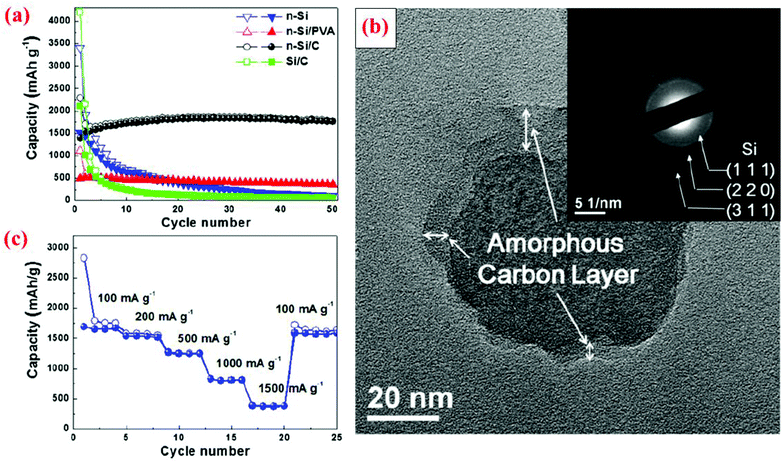 | ||
| Fig. 7 (a) Comparison of cyclability of n-Si, n-Si/PVA and n-Si/C electrodes at a constant current of 100 mA g−1, (b) TEM image with SAED of n-Si/C of the 20th cycle at the fully charge state to 1.5 V, and (c) rate capability test of the n-Si/C electrode at various current rates. Reproduced with permission.70 © 2012, Elsevier. | ||
Another study on the solid core–shell structure is executed by Zhang et al.71 The polyacrylonitrile (PAN)-coated Si precursor is formed through the emulsion polymerization of acrylonitrile in the presence of Si nanoparticles. In the next step, the precursor is heated up to 800 °C and turned into a Si@C core–shell structure. The presence of the amorphous conductive carbon shell which covers the whole Si particles prevents combination of particles during charge/discharge cycles. To prove the enhanced performance of this core–shell structure, another anode from virginal Si nanoparticles is fabricated and tested. The capacity of the bare Si nanoparticles has faded quickly after a few cycles (20 cycles), but the Si@C core–shell structure can retain half of its initial capacity after the same number of cycles. This proves the enhanced cycling behavior of the core–shell structure.
The same research group has published another research paper on the synthesis and properties of the Si@SiO core–shell structure synthesized through a sol–gel reaction combined with the heating step.72 Si nanoparticles (∼50 nm) are coated with a solution of tetraethylorthosilicate (TEOS), ethanol and water at pH between 8 and 9. Then, the aging process is done at 60 °C for 1 h. The formed gel is dried at ambient temperature for 2 days followed by heating at 70 °C for 6 h. After this step, all of the volatile compounds are completely removed from the material. The product is then ground to obtain a fine powder and heated to 500 °C for 6 h under an Ar atmosphere. The charge/discharge curves for this material indicates higher coulombic efficiency (CE) in the first cycle than pristine Si. As shown in Fig. 8, after 20 cycles the reversible capacity is around 600 mA h g−1 which is better than the nano-sized Si anode (<200 mA h g−1). This can be attributed to the presence of the SiO shell, which can result in half volume expansion (lithium silicates are formed) as compared to alloying between Si and Li ions. As a result, the SiO shell could act as a buffer and delay the collapse of the whole structure.
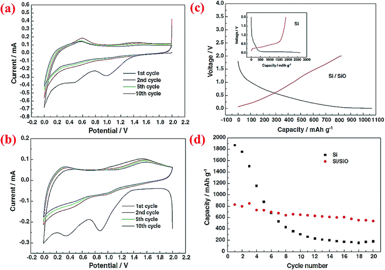 | ||
| Fig. 8 (a) CV curve for pure Si nanoparticles, (b) Si/SiO nanocomposite CV plot, (c) the first charge/discharge profile of Si and core–shell Si/SiO nanomaterial, and (d) discharge capacity of nano-Si compared to the Si/SiO composite for 20 cycles. Reproduced with permission.72 © 2006, Elsevier. | ||
A double-walled core–shell structure has also been investigated. In this case, Si nanoparticles (100–200 nm) are coated with double shells, SiO2 and C, and the material is denoted as Si@SiO2@C.43 Such a double-walled core–shell structure is synthesized by heating Si nanoparticles at 700 °C for 2 h to form a silica layer around the particles, followed by carbonization of epoxy resin at 700 °C to form the outer carbon coating. Half-cells of this Si@SiO2@C have been cycled between 0.01 and 5 V. Compared to Si nanoparticles and carbon-coated Si nanoparticles (Si@C), this double-walled core–shell structure shows much better capacity retention (Fig. 9). After 100 cycles the double-walled core–shell structure still exhibits a reversible capacity of 785 mA h g−1, which is far better than the single core–shell structure (Si@C) investigated in the same study (Fig. 9) as well as single core–shell structures of Si@SiO72 and Si@C71 studied earlier by other groups (see, for example, Fig. 7 and 8). The proposed electrochemical reaction for this double-walled core–shell structure is the following: when Li ions diffuse into the SiO2 shell, they react irreversibly and form Li4SiO4 alloy (eqn (1)). When Li ions reach the silicon core, a reversible lithiation reaction occurs (eqn (2)). This reaction determines the reversible capacity of the double-walled core–shell structure. This study43 unequivocally shows that the properties of the shell are critical in improving the capacity retention of the Si anode. The thin interlayer SiO2 enhances the adhesion of the carbon shell to the Si core and also alleviates stresses during cycles by acting as a buffering phase:
| SiO2 + 4Li+ + 4e− → Li4SiO4 + Si | (1) |
| Si + xLi+ + xe− ↔ LixSi | (2) |
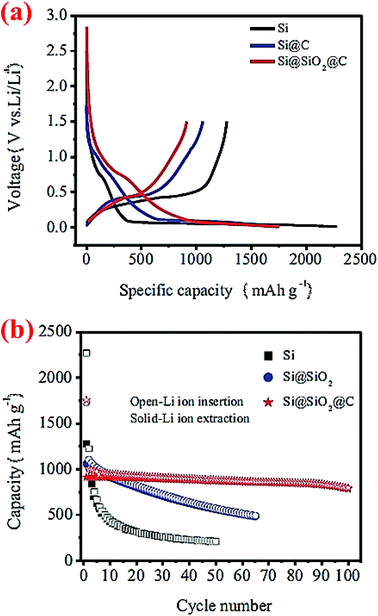 | ||
| Fig. 9 Cycling performance of double-walled core–shell structured Si@SiO2@C composites. Reproduced with permission.43 © 2014, Springer-Verlag. | ||
Solid core–shell structures with the shell made of metals have also been investigated. Cetinkaya et al.44 have employed the electroless deposition technique to prepare a silicon/copper composite. First, silicon particles (∼200 nm) are sensitized with SnCl2 and then activated with PdCl2. This pre-treatment makes the particle surface ready for the deposition step. The deposition is done in a plating bath containing the copper sulfate precursor. The plating process is performed at room temperature and the coating around the silicon particles is uniform.44 The mesoporous nature of the copper layer facilitates the diffusion of Li ions along with the enhanced conductivity of silicon particles. The cycle stability of Cu-coated Si is better than that of bare Si, but the gradual decay in the capacity of Cu-coated Si leads to only a marginal enhancement in the specific capacity over bare Si (Fig. 10), indicating that the Cu shell formed in this study is not very effective in improving the cycle stability of Si anodes.
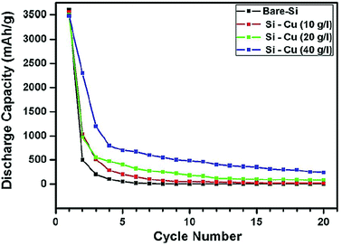 | ||
| Fig. 10 Cycling performance of copper coated silicon particles at different precursor concentrations in contrast to bare silicon particles. Reproduced with permission.44 © 2013, Elsevier. | ||
Another study on Cu-coated Si is conducted by forming a Cu shell on submicrometer-sized Si particles (380, 620, 730 and 940 nm) through the polyol-mediated reduction of Cu(II) acetate in a Schlenk line under an inert atmosphere.73 The details of synthesizing submicrometer-sized Si particles are reported in ref. 74 and 75. Metallic Cu with a small portion of Cu2O are deposited around Si particles. The formation of copper oxide is due to trace water impurities in the solution or exposure of the powder to air after synthesis. The Cu-coated Si (380 nm particles) exhibit a stable capacity at ∼600 mA h g−1 over 50 cycles,73 which is much better than that obtained by Cetinkaya et al. (Fig. 10).44 These results indicate that the quality of the Cu coating affected by synthesis conditions is important in determining the enhanced performance of Si anodes.
Solid core–shell structures with the shell made of TiO2 have also been explored.55 The TiO2 coating is formed via sol–gel processing of TiO2 in the presence of Si nanoparticles (70–100 nm). A specific capacity of 593 mA h g−1 is obtained after 50 cycles at 0.1 C. This value is comparable with those obtained from Si@SiO,72 n-Si@PVA,70 and Si@Cu,73 but much lower than those derived from double-walled Si@SiO2@C,43 n-Si@C with the Si core at 10 nm,11 and n-Si@C with the Si core <100 nm.70 In another experiment, Tang et al.76 have devised a method to synthesize n-Si@TiN to address the volume change, pulverization, SEI layer accumulation, and conductivity problems of silicon anodes. First, a TiO2 coating is formed around Si nanoparticles by hydrolysis of titanium tetrabutoxide (TBOT). Then, the powder is annealed under a N2 atmosphere to convert TiO2 to TiN. A comparison of n-Si and n-Si@TiO2 reveals that the electrochemical performance of n-Si@TiN is much better, delivering 2650 mA h g−1 at first discharge along with retaining 75% of the initial capacity after 100 cycles.
Taking all of the aforementioned results together, one can conclude that a conductive shell on the surface of Si particles can improve the cycle stability. However, to achieve this desired effect, the following three factors need to be taken into account simultaneously: (i) the size of the Si core (less than 100 nm is a must), (ii) the material of the shell (being conductive and electrochemically stable), and (iii) synthesis conditions that lead to a uniform, mechanically strong, and conductive shell.
3.3 Hollow core–shell structures
Very limited studies have been conducted on hollow core–shell structures (Fig. 2c) because hollow core–shell structures are far more difficult to synthesize than solid core–shell structures. One study conducted by Chen et al.77 does reveal that such a hollow core–shell structure can deliver outstanding performance. The hollow porous Si particles coated with the Ag shell, HPSi@Ag, are synthesized via a two-step synthesis (Fig. 11a). Sol–gel SiO2 is coated on the surface of polystyrene (PS) nanoparticles first, followed by calcination at 600 °C to burn out the PS core and form a hollow porous silica (HPSiO2) structure. The latter is then subjected to a magnesiothermic reduction to obtain hollow porous silicon (HPSi) nanoparticles. The HPSi nanoparticles (about 200 nm) are then coated with a carbon shell (HPSi@C) or silver shell (HPSi@Ag) to form the hollow core–shell structures. Fig. 11 summarizes some of the electrochemical testing results from the hollow core–shell structures. The charge and discharge capacities of the first cycle are 3146 and 3762 mA h g−1 with the coulombic efficiency of 84% for HPSi@Ag. The capacity remains high (∼3000 mA h g−1) after 100 cycles (Fig. 11c). This is because of the synergistic combination of the nanostructured material and formation of adequate void inside for volume expansion as well as the enhanced conductivity. In comparison, HPSi@C exhibits the second best performance, whereas HPSi nanoparticles show better performance than commercial solid Si nanoparticles. HPSi nanoparticles are doing better than solid Si nanoparticles because of the void inside to accommodate the volume expansion during lithiation. It is also worth mentioning that HPSi@Ag shows better results than HPSi@C, thanks to the higher electrical conductivity of Ag than that of carbon. HPSi@Ag nanoparticles also have excellent rate performance (Fig. 11d). Moreover, the Ag coating has resulted in decreased charge transfer resistance as shown in the impedance plot (Fig. 11e). Based on the electrochemical data, this structure can be a potential candidate for Si-based anodes in the next-generation Li-ion batteries.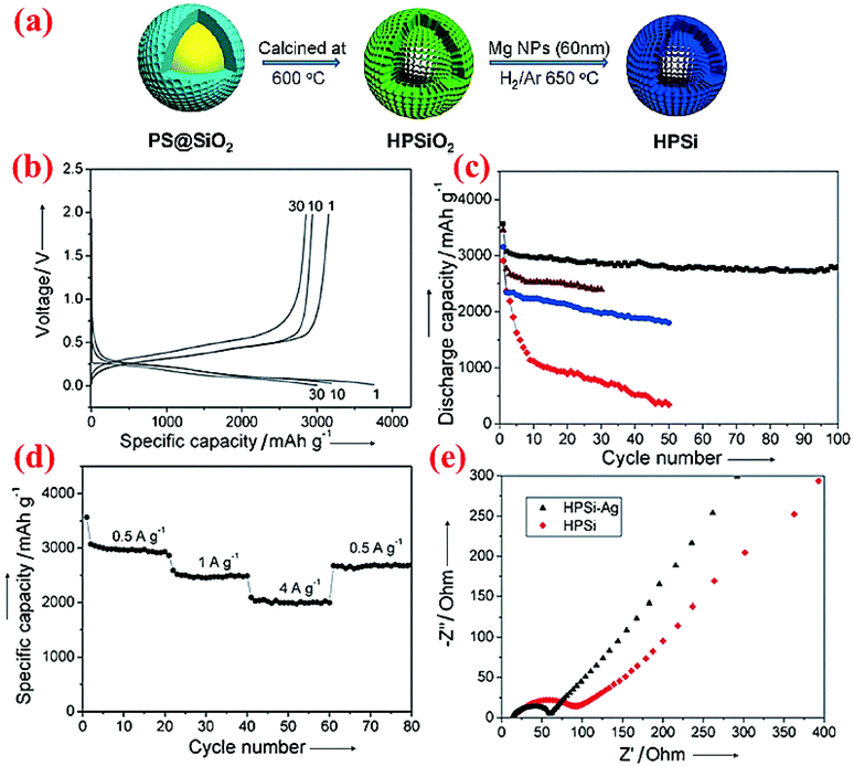 | ||
| Fig. 11 (a) Schematic of the fabrication of the hollow porous Si (HPSi) nanostructure, (b) charge and discharge profiles (measured vs. Li/Li+) of HPSi@Ag nanoparticles, (c) HPSi@Ag nanocomposite (black), HPSi@C nanocomposite (brown), HPSi nanoparticles (blue), and commercial Si nanoparticle discharge capacities, (d) HPSi@Ag nanoparticle capacities at different charge rates, and (e) the Nyquist plot for HPSi and HPSi@Ag nanoparticles. Reproduced with permission.77 © 2012, Wiley-VCH Verlag. | ||
3.4 Yolk–shell structures
Similar to solid core–shell structures, yolk–shell structures (Fig. 2d) have been studied extensively12,13,42,45,46,78,79 because they are relatively easy to synthesize compared to hollow core–shell structures. With yolk–shell structures the volume expansion of the Si particle inside the shell can be accommodated by the engineered void, whereas the conductive shell will allow electron and Li ion transport and offer a stable interface for good contact between various particles and the stability of the SEI layer. Multiple synthesis methods have been devised to form yolk–shell structures and thus different electrochemical properties are obtained.Zhou et al.78 have synthesized the Si@void@C yolk–shell structure by coating silicon nanoparticles with a SiO2 shell via sol–gel method, followed by coating of the Si@SiO2 particles with carbon using sucrose at 800 °C. Hydrofluoric acid (HF) is then used to dissolve the silica around the Si core, leading to the formation of the Si@void@C yolk–shell structure. The void between the core and shell provides sufficient space for expansion of the silicon core during lithiation without cracking in the carbon shell. Thermogravimetric analysis (TGA) reveals that the weight percentage of silicon is about 28.54%. The yolk–shell electrode could deliver 813.9 mA h g−1 at the first cycle and retain ∼500 mA h g−1 after 40 cycles (Fig. 12). The Si@void@C material has a higher cyclability than Si nanoparticles and hollow carbon. The voltage profile reveals that intercalation of Li ions into the carbon shell and SEI layer formation occur between 0.1 and 0.9 V with an even slope, while incorporation of Li ions into silicon is shown with a long plateau in the potential curve.
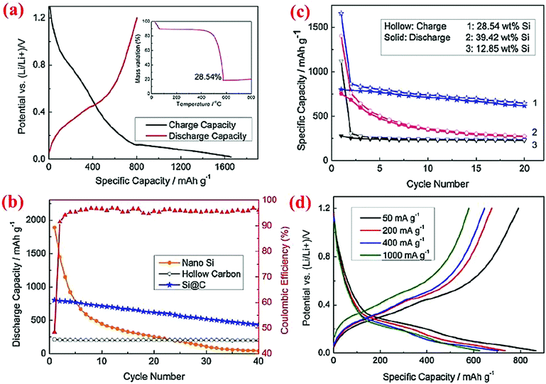 | ||
| Fig. 12 Electrochemical properties of the Si@C yolk–shell structure. Reproduced with permission.78 © 2012, Elsevier. | ||
Using a similar method, Tao et al.42 have also synthesized the Si@void@C yolk–shell structure, and obtained a very stable Si-based anode with ∼780 mA h g−1 after 100 cycles. Further, they have examined the effect of carbon loading in the Si@void@C yolk–shell structure, and found that 63% carbon loading leads to a higher specific capacity (∼780 mA h g−1) than 72% carbon loading does (∼690 mA h g−1). This result indicates that optimization of the design of the Si@void@C yolk–shell structure is needed to maximize the specific capacity of yolk–shell structures.
Li et al.79 have used a slightly different approach to synthesize the Si@void@C yolk–shell structure. The starting material is 50 nm Si powder. After calcination at 600 °C in the air, SiO2 is formed on the surface of the Si nanoparticles. The Si@SiO2 particles are then coated with a thin layer of carbon (about 5 nm) inside a vacuum furnace. The next step is HF etching to remove all traces of SiO2 from the powder to form the Si@void@C yolk–shell structure. The electrode constructed from this yolk–shell structure displays a discharge capacity of 1400 and 1100 mA h g−1 in the first and second cycles, respectively. Afterwards the capacity decay becomes small, and ∼750 mA h g−1 is retained after 60 cycles. This result is similar to those obtained by Zhou et al.78 and Tao et al.42 who have used a slightly different method to prepare the Si@void@C yolk–shell structure. In all of these studies,42,78,79 the cycle stability of the Si@void@C yolk–shell structure is always better than those of Si nanoparticles and solid Si@C core–shell structures, unambiguously demonstrating the advantage of the engineered void in providing a space for the Si core to expand with no crack formation in the carbon shell.
An outstanding study in yolk–shell structures was conducted by Liu et al.12 who have fabricated this nanostructure from the commercial silicon nanoparticles. A SiO2 sacrificial layer is coated on the surface of Si nanoparticles, followed by carbonization of a uniform layer of polydopamine to form the Si@SiO2@C structure. Finally, HF etching through the porous carbon shell is carried out to remove SiO2 and form the Si@void@C yolk–shell structure. The Si content in Si@void@C is ∼71 wt% based on the TGA measurement.12 The carbon shell formed in this study is very uniform, better than that reported by Li et al.79 As a result, outstanding cycle stability and high specific capacity are achieved. The capacity attained at the 1C rate is ∼1400 mA h g−1 after 1000 cycles, retaining 74% of the initial capacity with a coulombic efficiency of 99.84% (Fig. 13). In situ TEM has been employed to observe the lithiation/delithiation processes, in which Li ions penetrate the carbon shell and form an alloy with the silicon core. This study clearly reveals that well-engineered yolk–shell structures have the potential to serve as anodes for the next-generation LIBs.
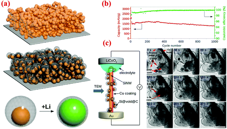 | ||
| Fig. 13 (a) Schematic of yolk–shell silicon structure and how it can be lithiated, (b) cycling performance and coulombic efficiency of yolk–shell designed anodes, and (c) in situ TEM observations of the lithiation process. Reproduced with permission.12 © 2012, American Chemical Society. | ||
Recently, yolk–shell structures with the shell made of SiO2 have also been studied. Sun et al.45 have synthesized such a Si@void@SiO2 yolk–shell structure using a vesicle template method. It starts with the preparation of spherical micelles consisting of the required surfactants. The addition of Si nanoparticles (about 30 nm diameter) along with a vesicle inducing agent into the micelle solution leads to the formation of the Si–vesicle complex. Subsequent addition of the SiO2 precursor, TEOS, results in the formation of a vesicle–silica composite with a discrete silica layer in the palisade layer of the vesicles. After removing the surfactants by HCl, the Si@void@SiO2 yolk–shell structure is formed. The SiO2 shell formed in this study is mesoporous with channels to facilitate the lithium ion passage. It is found that the specific capacity of the Si@void@SiO2 yolk–shell structure decreases on increasing the thickness of the SiO2 shell from 10 nm to 40 nm. A large irreversible capacity is observed in the first cycle process, which is mostly due to the formation of a SEI layer on the surface of the SiO2 shell and the irreversible electrochemical reactions between lithium ions and SiO2 to form Li2SiO3 and Li4SiO4. After the first cycle, cycling performances are significantly improved due to the formation of a stable SEI layer on the silica shell surface. The reversible capacity can be retained at 687 mA h g−1 at a current density of 50 mA g−1 after 30 cycles.45 This performance is slightly below that obtained from Si@void@C yolk–shell structures42,78,79 and far below the well-synthesized Si@void@C yolk–shell structure,12 suggesting that carbon is a better choice than SiO2 for the shell material, presumably due to the better electrical conductivity of carbon than that of SiO2.
Sun et al.46 have recently extended their vesicle template method45 to form silicon/double-shelled carbon (Si@DC) yolk-like nanostructure (Fig. 14). Their synthesis starts with the Si@void@SiO2 yolk–shell structure made using the vesicle template method. The Si@void@SiO2 template is then coated with a glucose-derived polysaccharide on both the interior and exterior surfaces of the porous SiO2 shell. A subsequent annealing process at 800 °C for 4 h under an argon atmosphere results in the carbonization of the polysaccharide component, leading to the formation of a Si@void@C@SiO2@C structure. Finally, the SiO2 shell is dissolved in hydrofluoric acid to generate the Si@DC powders with a Si@void@C@void@C configuration. This dual yolk–shell material has a very high conductivity because of the presence of two carbon shells. The authors have also synthesized Si/single-shelled (Si@SC) and Si/three-shelled (Si@TC) nanopowders, but the best result is obtained with Si@DC. As shown in Fig. 14, the specific discharge capacity of Si@DC remains as high as 943.8 mA h g−1 at 50 mA g−1 after 80 cycles, which is higher than the Si@SC (719.8 mA h g−1) and bare Si electrode (115.3 mA h g−1).
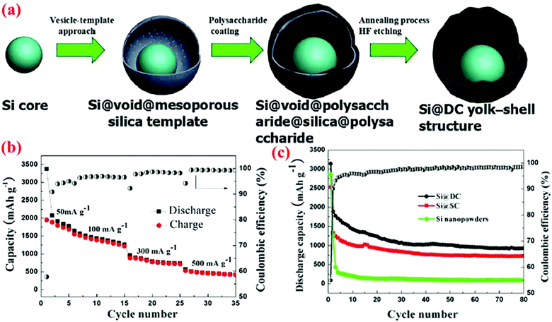 | ||
| Fig. 14 (a) Synthesis route of Si@DC based on the vesicle-template approach, (b) capacity retention curve at different current densities, (c) discharge capacity and coulombic efficiency of Si@DC nanoparticles in contrast with Si@SC and Si nanopowder. Reproduced with permission.46 © 2015, The Electrochemical Society. | ||
The dual yolk–shell concept has also be explored with carbon and SiO2 as the dual shells lately.13 The dual yolk–shell structure in this case can be described as Si@void@SiO2@void@C. To form this structure, Si nanoparticles are coated with a SiO2 layer via the Stöber method and then the Si@SiO2 particles are coated with a carbon layer. Taking advantage of the inhomogeneous nature of the silica shell prepared by the Stöber method, proper etching via HF treatment can selectively etch a small portion of the outer layer and a large portion of the interior layer of the SiO2 shell, leading to the formation of the Si@void@SiO2@void@C structure. In this dual yolk–shell structure, carbon improves the conductivity, while silica increases the mechanical stability and the void provides enough space for the volume expansion of the silicon core. Further, the SiO2 and C dual shells can offer a double barrier to prevent the electrolyte from reaching the surface of the silicon nanoparticles and protect the anode from subsequent irreversible reaction with the electrolyte. The dual yolk–shell structure has exhibited superior capacity retention (83%) with a specific capacity of 956 mA h g−1 at a current density of 460 mA g−1 after 430 cycles, while the capacity of the Si@C core–shell structures decreases rapidly in the first ten cycles under the same experimental conditions (<200 mA h g−1 after 430 cycles). The performance of this Si@void@SiO2@void@C structure is much better than that of the Si@void@C@void@C structure,46 indicating that the processing methods and conditions are important in realizing the potential of the dual yolk–shell design.
IV. Porous silicon designs
The principles of using porous Si designs to enhance the performance of Si anodes are similar to those of hollow core–shell structures and yolk–shell structures, i.e., the void space introduced during synthesis can allow the silicon in the engineered structure to expand during lithiation with little or no change in the volume of the entire particle. This minimized volume expansion and shrinkage prevents particle fracture and leads to a stable SEI layer on the surface of the particle, while keeping all or most of particles in contact with conductive pathways. Multiple methods have been investigated to create various porous Si structures.16–19,80 Like hollow core–shell structures and yolk–shell structures, all of the porous Si designs studied so far have offered better electrochemical performance than bare Si nanoparticles or solid core–shell structures.16–19,804.1 Nanosized porous silicon
Liu et al.17 have developed a novel method to produce mesoporous Si nanoparticles from the husks of rice, the second most copious crop in the world. The method consists of acid wash of rice husks, filtration, deionized water wash and calcination of the leached product at 700 °C to yield nano-SiO2. Magnesiothermic reduction of the nano-SiO2 powder followed by acid etching is required to attain Si nanoparticles which have particle sizes ranging from 10 to 40 nm. BET measurement reveals the mesoporous nature of the collected particles (surface area of 245 m2 g−1 and pore volume of 0.74 cm3 g−1). The mesoporous Si nanoparticles are utilized to make half-cells without any carbon coating. The results are extraordinary. The first cycle discharge capacity is 2790 mA h g−1 which decreases in the following cycles, but remains ∼1700 mA h g−1 after 300 cycles at the C/2 rate. The capacity is ∼2200 mA h g−1 after 100 cycles at the C/5 rate. The superior capacity and rate capability are attributed to nanoparticle sizes, large surface area, and the presence of mesopores to accommodate the volume expansion of Si during lithiation. The propensity of cracking and instability of SEI layers is further reduced by nanoparticle sizes, while large surface area shortens the diffusion path for Li ions, enhancing the rate capability.314.2 Micro-sized porous silicon
Yi et al.16 have developed a different method to synthesize porous Si materials using nano-sized silicon particles as building blocks for micro-sized porous Si particles. The starting material is a commercial micro-sized SiO powder which becomes a Si/SiO2 mixture after disproportionation at 950 °C for 5 h (Fig. 15). Subsequent HF etching of the Si/SiO2 mixture results in the formation of micro-sized porous Si particles. Finally, carbon coating of the porous Si is done by thermal decomposition of acetylene at 620 °C for 20 min. SEM analysis reveals that the porous Si–C composite has an average particle size of 20 μm, while TEM analysis indicates that the interconnected Si nanoparticles which form the micro-sized particles have a size of about 10 nm. Further, carbon is uniformly distributed among the interconnected Si nanoparticles. This porous Si–C material shows a higher capacity than bare silicon and could deliver 1459 mA h g−1 after 200 cycles at 1 A g−1 (Fig. 15). In addition, it shows perfect rate performance of 700 mA h g−1 at 12.8 A g−1. Further, its tap density is high (0.78 g cm−3) and thus can give a high volumetric capacity (1326 mA h cm−3 at 400 mA g−1 after 50 cycles). The reported synthesis method is low cost and easy to scale up with a potential for mass production for the next-generation Li-ion batteries.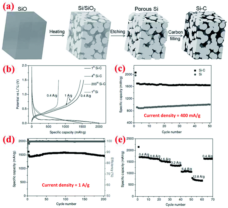 | ||
| Fig. 15 (a) Schematic of the synthesis procedure of micron-sized porous Si/C composites, and (b–e) electrochemical performance. Reproduced with permission.16 © 2013, Wiley-VCH Verlag. | ||
The same group has further examined the effect of disproportionation temperature on the size of Si nanoscale building blocks and found that Si building block sizes are 10, 15, 30 and 80 nm when the disproportionation temperature is 950, 1100, 1300 and 1400 °C, respectively.80 The initial charge/discharge capacities are found to increase with the disproportionation temperature because finer Si building blocks have larger surface areas and thus more surface SiO2 present in the micro-sized porous Si/C materials (Fig. 16). However, finer Si building blocks (10 and 15 nm) show far better cycling stability than larger Si building blocks (30 and 80 nm) because smaller building blocks have smaller volume change and thus more stable SEI layers. As shown in Fig. 16, the micro-sized porous Si/C material with the Si building block at 15 nm has the best combination of these characteristics and thus exhibits the highest capacity at 1800 mA h g−1 (calculated based on the weight of Si and C in the porous material) after 100 cycles at a current density of 400 mA g−1. The authors have also found that the carbon coating temperature of 800 °C is better than 650 °C because of the synergistic effect of better carbon quality (higher degree of graphitization and thus better electrical conductivity) and the reduction of SiOx on the surface of Si building blocks. The micro-sized porous Si/C material with a carbon loading of ∼20 wt% deposited at 800 °C exhibits a fixed capacity of 1200 mA h g−1 over 600 cycles at 1.2 A g−1 with a coulombic efficiency of 99.5% and no capacity decay.80 As far as we know, this is the best cycling performance with such a high capacity for micro-sized Si-based anodes.
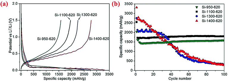 | ||
| Fig. 16 (a) First cycle discharge capacity, (b) cycling performance curves of the micro-sized porous Si/C materials synthesized at different disproportionation temperatures. Reproduced with permission.80 © 2013, Wiley-VCH Verlag. | ||
In another study,19 micro-sized porous Al–Si particles are synthesized via a facile selective etching process of Al–Si alloy powder. Subsequent thin Al2O3 layers are introduced on the surface of the micro-sized porous Si particles via a selective thermal wet oxidation process of the etched Al–Si particles. The resulting porous Si particles wrapped with thin Al2O3 layers offer outstanding cycling stability (a capacity retention of 78% of its original capacity of ∼1000 mA h g−1 after 300 cycles at the C/5 rate) and excellent rate capability.
Other studies18,81–85 on micro-sized porous Si/C materials have also demonstrated a high specific capacity with good cycling stability. Another important advantage of these micro-sized porous Si-based materials is their high tap densities. As a result, these porous materials also possess a high volumetric capacity. For example, a recent study18 reports a high volumetric capacity at 1088 mA h cm−3, which is 5 times that of commercially available nano-Si based anodes. Therefore, micro-sized porous Si-based materials are a strong contender as a high rate, high capacity, and cycling-stable anode for the next-generation LIBs.
V. Nanowires, nanotubes and nanofibers
One-dimensional (1D) nanowires, nanotubes and nanofibers have the advantage of allowing the expansion of silicon radially to minimize the cracking propensity. Furthermore, if an electrically conductive coating is present on the surface, these 1D nanowires, nanotubes and nanofibers can have robust electrical transport along the wire and tube axis while Li ion transport can be accomplished radially with a very short distance. As a result, these 1D nanowires, nanotubes and nanofibers can have a high specific capacity and superior rate capability with long cycle stability.4,86–90 Indeed, one of the best electrochemical performances among all the Si anodes is achieved with double-walled silicon nanotubes.89 However, one of the drawbacks for nanowires and nanotubes is that their electrode making process is different from the current powder-based electrode making process used commercially. New electrode making processes at low cost need to be developed for these emerging materials. Below are the key properties of Si nanowires and nanotubes obtained by various groups.5.1 Silicon nanowires (SiNWs)
Chan et al.4 have fabricated very small size nanowires which provide enough space for the expansion of silicon radially (Fig. 17). These nanowires are made via chemical vapor deposition (CVD) of silicon on the stainless steel foil with stout mechanical and electrical properties.4 Interestingly, these Si nanowires have sufficient electronic conductivity along the longitudinal axis and can operate without the presence of any carbon. Fig. 17a and b illuminate the differences between SiNWs and silicon particles by comparing the morphological changes before and after cycling. Exclusive electrochemical performance of SiNWs is displayed in Fig. 17c and d. Oxidation/reduction peaks of silicon can be observed in the cyclic voltammogram (CV). The discharge capacity at the first cycle is 3124 mA h g−1 and the battery could keep the capacity after 10 cycles with slight fading which is a sign of a stable morphology and no loss of active materials. SiNWs can retain their capacity after 10 cycles, which makes them a potential candidate for replacing graphite which is currently used in regular Li-ion batteries.14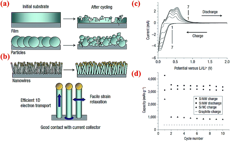 | ||
| Fig. 17 Comparison of morphology changes of (a) silicon particles and (b) silicon nanowires after cycling, (c) CV data for SiNWs for 7 cycles, (d) comparison of the electrochemical performance of SiNWs, silicon nanocrystals (SiNCs) and graphite after 10 cycles. Reproduced with permission.4 © 2008, Nature Publishing Group. | ||
In the search for a facile and low cost synthesis method of SiNWs, Zhang et al.90 have introduced a novel crystalline silicon core with amorphous silicon oxide shell nanowires. In their process, silica and titanium powder as catalysts are mixed together and heated under an argon atmosphere up to 1600 °C. After characterization, the growth of SiNWs in the [111] direction is observed, but the growth mechanism is different from typical VLS growth. The authors found that the formation of silicon spheres at lower temperatures (e.g. 1400 °C) facilitates continuous growth of nanowires. The electrochemical performance of this material is fair, about 1640 mA h g−1 discharge capacity after 100 cycles at 1 A g−1 current density.
5.2 Silicon nanowalls (SiNWLs)
Wan et al.47 have designed and fabricated 2-dimensional Si nanowalls (SiNWLs) to address the large irreversible capacity loss during the first cycle. Since the 2-D nanowall structure design could reduce 50% of the specific surface area compared to the nanowire structure with a similar geometric dimension, the SiNWLs will have less material exposed to the electrolyte. Thus, the design could limit the side reactions occurring at the anode–electrolyte interface which consume lithium ions to form SEI layers, and has improved the first coulombic efficiency to 83.4%. To fabricate the SiNWLs, nanoimprint lithography (NIL) method along with deep reactive ion etching (DRIE) are utilized to create the periodic and disconnected nanowalls (Fig. 18). The finite element package ABAQUS is used to simulate the mechanical deformation in the material. The results reveal that the mean stress level varies with time, and the distribution of the tensile mean stress at the mid-plane and outer surface is non-uniform. While the interior surfaces are more susceptible to form pores during the lithiation process triggered by the higher tensile mean stress in the middle part, the outer surfaces experience the pore formation in the delithiation process. As a result, the entire structure experiences a relatively homogeneous pore distribution after many cycles.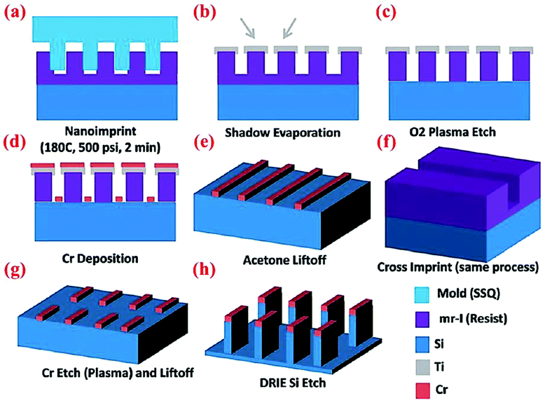 | ||
| Fig. 18 Schematic of multiple steps of the NIL process to obtain SiNWLs. Reproduced with permission.47 © 2014, The Royal Society of Chemistry. | ||
5.3 Silicon nanotubes (SiNTs)
Silicon nanotubes (SiNTs) have attracted extensive attention. Park et al.87 have utilized Si nanotubes with a thin layer of carbon as a coating and by this method, they allow Li ions to react on both the inner and outer surfaces of the tubes (Fig. 19). The coin cells are fabricated with SiNTs and tested. At the 0.2C rate, 3648 and 3247 mA h g−1 capacities are obtained in the first discharge and charge cycles, respectively. These capacities show a coulombic efficiency of 89% which is really high for the first cycle. The thin carbon layer is the main mechanism for this value of efficiency. The capacity at different charge and discharge rates shows a stable and specific capacity of ∼2700 mA h g−1 even after 200 cycles (Fig. 19).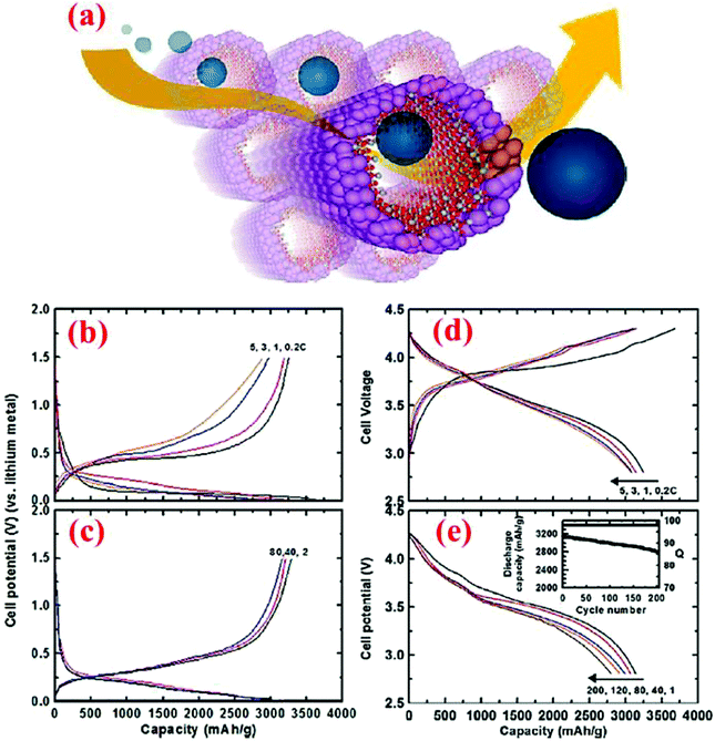 | ||
| Fig. 19 (a) Simulated pathways of Li ions in SiNTs, (b and c) voltage profiles of the coin-type half cells at a charge rate of 1C and discharge rate ranging from 0.2C to 5C; and (d and e) voltage profiles of the pouch-type full cells (LiCoO2 was the cathode) for 200 cycles. Reproduced with permission.87 © 2009, American Chemical Society. | ||
To achieve a method for large-scale production of SiNTs, Wen et al.88 have employed magnesiothermic reduction to convert silica nanotubes to SiNTs. First, silica nanotubes are synthesized with rod-like NiN2H4 as a templating agent and TEOS as a silica precursor. Next, silica powder is collected and reduced to SiNTs with magnesium powder at 660 °C for 3 h under an argon atmosphere. Etching with 0.5 M HCl removes unwanted products such as Mg2Si and MgO. The rate capability and cycling performance of SiNTs are much better than those of Si particles (mesh 325). SiNTs have exhibited more than 1000 mA h g−1 at 0.5C after 90 cycles while the Si particles could only deliver 500 mA h g−1. The nanostructure helps to buffer the volume change of Si and also provides a high surface area (113 m2 g−1) for lithium ion intercalation.
5.4 Double-walled silicon nanotubes (DWSiNTs)
Wu et al.89 have developed double-walled silicon nanotubes (DWSiNTs) which combine two astonishing aspects together: the outer surface of this structure gives enough space for the stabilized growth of the SEI layer and the inner space provides space for expansion of silicon during cycling. The internal structure contains Si while the external structure is made from SiOx. Li ions can pass through the outer SiOx layer and meanwhile this layer is strong enough to keep the structural integrity. The SEI layer forms around the outer tube uniformly, and this material has passed 6000 cycles at 12C without significant capacity loss (88% capacity retention). Fig. 20 demonstrates some of the excellent electrochemical characteristics of this material. To our knowledge, 6000 cycles are the longest cycle life ever reported for Si anodes in the open literature.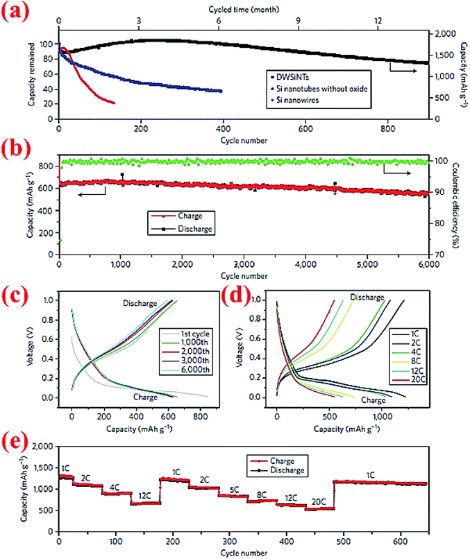 | ||
| Fig. 20 (a) Comparison of the capacity retention over cycles between DWSiNT and SiNWs at C/5; (b) capacity plot of DWSiNT anodes for 6000 cycles at 12C; (c) voltage vs. capacity plot for 1000 cycles; (d) and (e) lithiation/delithiation profiles at different C-rates for multiple cycles. Reproduced with permission.89 © 2012, Nature Publishing Group. | ||
5.5 Silicon nanofibers
In one of the recent studies, Hwang et al.91 have fabricated peculiar electrospun core–shell Si fibers. In their process the dual nozzle electrospinning machine is loaded with both the core polymer (containing Si nanoparticles and polymethylmethacrylate (PMMA) dissolved in N,N-dimethylformamide (DMF) and acetone) and the shell polymer (polyacrylonitrile (PAN) dissolved in DMF). One-dimensional fibers are formed in one step. Subsequently, fibers are carbonized to convert PAN to the carbon shell and eliminate PMMA inside the Si core (Fig. 21). Half-cells are made with these Si@C core–shell fibers and on each anode around 0.6 mg cm−2 of active material is loaded. A wide range of current densities is applied to the coin cell batteries fabricated with this material (from C/10 to 12C). At the lowest current density (C/10), the delivered capacities are reported as 1491 and 1305 mA h g−1 in the delithiation/lithiation procedure, respectively. This capacity is maintained quite well after 40 cycles. Further, at a high current density (12C) the cells can still deliver a specific capacity of ∼750 mA h g−1 (Fig. 21), indicating high rate capability and good cycle stability.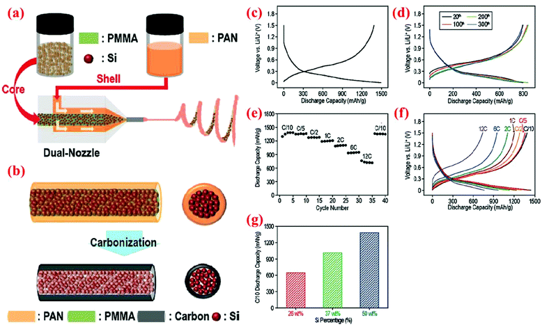 | ||
| Fig. 21 Core–shell nanofibers produced by (a) a dual nozzle electrospinning machine, followed by (b) the carbonization step, (c–f) electrochemical performance, and (g) discharge capacity (measured at the C/10 rate) vs. weight portion of silicon. Reproduced with permission.91 © 2011, American Chemical Society. | ||
Wu et al.92 have developed a slightly different method to synthesize Si@C core–shell nanofibers. In this process a SiO2 precursor solution is mixed with Si nanoparticles first. With the aid of an electrospinning machine, Si/SiO2 nanofibers are then generated from the suspension. To form the carbon coating, polystyrene as the carbon precursor is carbonized. The carbon layer is very thin and does not destroy the porous nature of the Si/SiO2 core. The final step is etching with a HF solution to remove SiO2. The entire method is low cost and scalable. Furthermore, the Si@C core–shell nanofibers are able to retain 90% of their original capacity and provide a specific capacity of ∼870 mA h g−1 after 200 cycles, demonstrating the advantage of encapsulating silicon nanoparticles in carbon nanofibers.
An interesting modification of Si nanofibers is PPy@Si nanofibers fabricated by Du et al.93 The polypyrrole (PPy) fibers are produced by electropolymerization of pyrrole monomer, followed by a uniform coating of Si on the fibers via the CVD technique. The PPy core is inactive and acts as a backbone to provide the mechanical properties and enhance the electrical conductivity of nanofibers. This material is used as an active material for the anode without any binder or conducting agent. The battery is tested for 100 cycles and delivers more than 2800 mA h g−1. These outstanding properties have been attributed to the conductivity and the porous three dimensional network of the nanofibers, which is perfect for volume expansion of silicon during cycling.93
Recently, Lee et al.94 have published a paper on the fabrication of Si core/C shell nanofibers. This work was carried out by using an electrospinning machine equipped with a co-axial nozzle with two concentric cylinders. They have used PAN (polyacrylonitrile) as the carbonizing precursor, SAN (styrene-co-acrylonitrile) as the sacrificial core, and Si nanoparticles are loaded inside as the permanent core. The electrospun material is heated to burn the sacrificial core. The obtained nanofibers are tested with contact lithiation. The results indicate no reaction between carbon and silicon and both the core and shell are lithiated separately. The silicon core volume expansion is confined completely inside the stable carbon shell. An initial charge capacity is reported as high as 967 mA h g−1 at 0.5 A g−1 current density with 92% capacity retention after 50 cycles.
VI. Si-based composites
Generally speaking, when Si is mixed with other materials, it is a Si-based composite. In this broad sense, almost everything that has been reviewed from sections III to V is a composite. To avoid confusion and repetition, however, we exclude everything that has been reviewed in sections III to V from the composite category, and focus our attention on three groups of Si-based composites. These are categorized as (i) Si/graphene and Si/nanographite sheet composites, (ii) Si/CNT, Si/CNF, and Si/graphite powder composites, and (iii) Si mixed with other material composites.6.1 Si/graphene and Si/nanographite sheet composites
These composites have been studied extensively51–54,95 because graphene has outstanding electronic conductivity and can also serve as a substrate to constrain volume expansion of Si particles during cycles. Nanographite sheets can be considered as multi-layer graphenes, but with lower costs and lower electronic conductivities. The studies in this area have revealed that the addition of graphene can improve capacities and cycle stability, but graphene alone does not provide the best properties. The best electrochemical performance is obtained from the synergistic functions of graphene, carbon coating, and nano-sized Si, as discussed below.Su et al.54 have developed a procedure to synthesize a Si/graphite@graphene composite with the structure of a Si/graphite mixture wrapped by graphene sheets. This composite is produced by mixing graphene oxide with nano-Si (30 nm) and graphite (∼500 nm) in an alcohol solution, followed by spray-drying and then heating at 450 °C to reduce graphene oxide to graphene. The composite exhibits an initial charge capacity of 803 mA h g−1 at 100 mA g−1 and retains ∼500 mA h g−1 after 50 cycles. The capacity decay slope, however, is close to a linear function of the cycle number, suggesting that the capacity retention needs to be improved in the future.
In a separate study carried out by Ma et al.,52 carbon-coated Si nanoparticles supported by exfoliated graphite (EG) are synthesized by dispersing polyvinyl chloride (PVC)-coated Si nanoparticles (<100 nm) with EG in a tetrahydrofuran (THF) solution, followed by heating the dried mixture at 900 °C for 2 h under an Ar atmosphere to convert PVC to carbon. The composite displays a high capacity of ∼900 mA h g−1 at a current density of 200 mA g−1 and remains at this capacity over 40 cycles, indicating an excellent cycling stability. In contrast, carbon-coated Si nanoparticles only have a capacity of ∼100 mA h g−1 under the same testing conditions after 40 cycles, unambiguously indicating the importance of EG as a flexible and conductive support in enhancing the cycling stability. In comparison with the study by Su et al.,54 this work also shows that carbon coating on Si nanoparticles is important for cycling stability even with the support of graphene or exfoliated graphite.
The synergistic effects of the carbon coating and graphene support in Si/graphene composites were further demonstrated by a study conducted by Yi et al.95 In their process micro-sized SiO and graphene oxide (GO) are first mixed in water in the presence of poly(diallyldimethylammonium chloride) (PDDA) which serves as a positively charged medium to attract GO and SiO. The GO/PDDA–SiO mixture is then heated to 950 °C for 5 h, followed by HF etching at room temperature to create micro-sized porous Si supported by graphene (G/Si). Carbon coating is subsequently deposited on the surface of G/Si via thermal decomposition of acetylene at 800 °C for 10 min. The carbon-coated, graphene-supported, micro-sized porous Si (denoted as G/Si–C) exhibits a high specific capacity (∼1150 mA h g−1) and remains at this level after 100 cycles (Fig. 22). The outstanding capacity retention is attributed to the synergistic effects of the carbon coating, graphene support and porous Si with nano-sized building blocks. This well-engineered Si structure also allows high active material loading in the anode, leading to high areal capacities (3.2 mA h cm−2 after 100 cycles) with no decrease in the specific capacity (Fig. 22b). In contrast, the specific capacity of the carbon-coated, micro-sized porous Si (Si–C) decreases sharply by high mass loading (Fig. 22d), indicating the importance of the conductive function of graphene in linking all Si particles together regardless of their distance from the current collector.
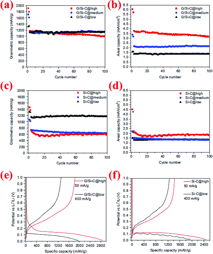 | ||
| Fig. 22 (a–d) Comparison of the cycling behavior of graphene/Si–C and Si–C composites at different mass loadings, (e and f) voltage profile of G/Si–C and Si–C composites for the first cycle at high and low mass loadings. Reproduced with permission.95 © 2014, Elsevier. | ||
6.2 Si/CNT, Si/CNF, and Si/graphite powder composites
Carbon nanotubes (CNTs), carbon nanofibers (CNFs) and fine graphite particles can all provide electron transport pathways and serve as effective substrates to constrain volume expansion of Si particles during cycles.50,96,97 CNTs and CNFs have additional advantages over fine graphite particles in terms of their continuous electronic pathways, and thus are more effective in enhancing the electrochemical performance of Si anodes than fine graphite particles but at higher costs.Zhang et al.50 have developed an interesting synthesis procedure to produce a low-cost Si/CNT&CNF composite made of carbon-coated Si nanoparticles interweaved with CNTs and CNFs, denoted as Si@C/CNTs&CNFs. Their synthesis procedure starts with ball milling of Si to form Si nanoparticles which are then mixed with citric acid in a nickel acetate–ethanol solution. The resulting suspension is then spray dried under a N2 atmosphere, followed by heating at 380 °C for 4 h under a N2 atmosphere. These steps lead to Si@C particles with nickel oxide dispersed on their surfaces. The obtained Si@C particles are then subjected to a C2H2/N2 treatment at 700 °C for 3 h to form the Si@C/CNT&CNF composite. In this last step the nickel oxide acts as a catalytic agent to promote the growth of CNTs and CNFs. The obtained composite displays high capacities with superior cycling stability (1195 mA h g−1 after 50 cycles at 300 mA g−1). In contrast, Si@C without CNTs and CNFs shows insufficient capacity retention (only 601 mA h g−1 after 50 cycles), whereas Si nanoparticles without carbon coating have the worst performance with its capacity dropping to nearly zero after 15 cycles.50 The performance of Si@C being better than that of Si nanoparticles is in good accordance with a large number of studies discussed in sections 3.1 and 3.2. The best performance of Si@C/CNTs&CNFs has been attributed to the function of CNTs and CNFs in providing continuous electronic pathways by linking most of the Si@C particles together and offering the void space (interweaved with Si@C particles) to absorb the volume expansion in lithiation, thereby providing a great reduction in the conduction network breakage during cycles and thus superior cycling stability.50
In a separate study,97 the importance of linking most of the Si nanoparticles together by a conductive network has also been demonstrated. In this study Si nanoparticles are attached to graphite microparticles which provide a conductive network to allow fast charge and discharge of Si nanoparticles with superior cycle stability. A polymer blend consisting of poly(diallyldimethylammonium chloride) and poly(sodium 4-styrenesulfonate) is used to enable a uniform distribution of Si nanoparticles on graphite microparticles and serve as a robust artificial solid–electrolyte interface. Due to these synergistic effects, the composite electrode displays a specific capacity of 450 mA h g−1, 96% capacity retention at a 10C rate, and 95% retention after 200 cycles.97
6.3 Si mixed with other material composites
This group includes Si/ceramic, Si/polymer, Si/metal, and Si/intermetallic composites. This group can offer positive surprises if the design principles to solve the Si anode problems are followed.20–22,24,98 Several examples along this direction are presented below.An interesting example of Si/ceramic/metal/carbon composites is the a-Si–SiOx/Cr/C composite made lately by Li et al.20 A simple, scalable two-step method is used to synthesize such a composite. The commercial SiO powder is first subjected to a disproportionation reaction at 1000 °C for 3 h to form the Si/SiOx nanoscale mixture which is then ball milled with micro-sized Cr and graphite powders. As shown in Fig. 23, the obtained composite exhibits a high specific capacity (810 mA h g−1) with capacity retention close to 100% over 200 cycles at a current density of 100 mA g−1. For comparison, other composites without graphite (a-Si–SiOx/Cr), without Cr (m-c-Si–SiOx/graphite), and without Cr and graphite (m-c-Si–SiOx) have been synthesized and tested. All of them have displayed poor cycling stability (Fig. 23). It is found that the high hardness of Cr powder has resulted in the formation of a-Si-SiOx in very fine particle sizes during ball milling. As a result, a small volume change takes place per particle during cycles, thereby minimizing the loss of particle contact and the stress causing the fracture and re-formation of SEI layers.20 It should be emphasized that the specific capacity reported in this study is based on the total weight of the a-Si–SiOx/Cr/C composite. Combining its high capacity and outstanding capacity retention with its low cost and easily scalable processing method, this composite has the potential to serve as the anodes for LIBs in the future.
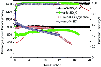 | ||
| Fig. 23 Comparison of the specific discharge capacity of SiO/graphite, c-Si–SiOx/graphite, a-Si@SiOx/Cr and a-Si@SiOx/Cr/C vs. cycle number. Reproduced with permission.20 © 2015, Elsevier. | ||
Han et al.22 have also utilized high-energy ball milling to synthesize a Si/silicide nanocomposite. The synthesis consists of two straightforward steps with the first step being arc melting of an elemental mixture of Si, Fe and Cr to create a Si80Fe16Cr4 master alloy and the second being high-energy ball milling of the master alloy for 8 or 10 h to create the uniformly mixed Si + FeSi2 + CrSi2 nanocomposite. The composite can deliver an initial delithiation capacity of ∼900 mA h g−1 and remain at ∼840 mA h g−1 at the 1C rate after 100 cycles, showing an excellent capacity retention behavior.22 The primary factors contributing to the excellent electrochemical performance are the size reduction of Si particles to the nanometer scale (∼5 nm), the formation of a highly elastic FeSi2 + CrSi2 matrix which can accommodate the volume change of Si, and separation of the silicide phases from Si after extended cycling.22
High-energy ball milling has also been studied to make Si/polymer composites. In one of the earliest studies,98 a polypyrrole (PPy) film is ball milled with commercial Si to form the Si/PPy composite. Mixing silicon nanoparticles with PPy fulfils two requirements. First, PPy is a conductive polymer and thus improves the conductivity of the composite. Second, it also acts as buffer to prevent crack formation and pulverization of silicon. The composite is able to deliver 1800 mA h g−1 at the first discharge which, however, is suppressed to lower values at subsequent cycles, indicating that improvements are needed in order to compete with other Si anode technologies in the future.
High-energy ball milling typically leads to uniformly mixed composite structures, as shown above. To obtain particle structures other than uniformly mixed composites, different methods have to be devised. Lee et al.21 have explored electrical wire explosion of a Ni wire in a Si nanoparticle-dispersed suspension with oleic acid (OA) as the liquid medium to produce a Ni–Si nanocolloidal suspension. The Ni–Si colloids are then dried and subjected to a 500 °C heat treatment to carbonize OA and form carbon-coated Ni–Si nanocomposites. The resultant composite is composed of a Ni (5–10 nm) and Si (∼100 nm) particle mixture coated with a thin carbon layer (∼5 nm). The Ni–Si@C nanocomposites are able to deliver high reversible capacities of ∼3500 and 2000 mA h g−1 of Si at current densities of 84 and 840 mA g−1 of Si, respectively, whereas the bare Si nanoparticle electrode examined under the same conditions only possesses specific capacities of ∼1200 and 280 mA h g−1 of Si, respectively. The outstanding electrochemical performance of the Ni–Si@C nanocomposite has been attributed to the following reasons: (i) the distributed small Ni nanoparticles and carbon coating improve the surface electrical conductivity of the Si nanoparticles, resulting in a highly efficient conducting network of the electrode; (ii) the uniform carbon coating surrounding each Ni–Si particle effectively buffers the stress of volume excursions and acts as a barrier against the reaggregation of the nanoparticles during repeated cycles; and (iii) the high pore volume and large specific surface area of the nanocomposite facilitate the rapid penetration of the electrolyte and provide a large contact area between the electrolyte and the electroactive surface of the Ni–Si@C nanocomposites, thereby providing efficient transport of Li ions throughout the electrode and a high specific capacity, as well as sufficient void space to absorb the volume expansion.
VII. Unusual designs
Some of the Si material designs have unique features and do not fall into any of the categories discussed above. Thus, we have assigned them to the “unusual designs” category. Because of their unique structures these unusual designs often possess exceptional properties. Here we have selected several of them to highlight their synthesis strategies and structure–property relationships.7.1 Hollow porous silica nanocubes (HPSNCs)
Yan et al.99 have developed a two-step hard-templating process to fabricate silica nanocubes. Co3[Co(CN)6]2 nanoparticles are employed as the primary core and coated with silica using tetraethyl orthosilicate (TEOS) as the precursor (Fig. 24). After annealing at 550 °C, the Co3[Co(CN)6]2 core becomes Co3O4, which is then etched away by hydrochloric acid to acquire hollow porous silica nanocubes. At the first cycle, HPSNCs are able to deliver 3048 and 1457 mA h g−1 for discharge and charge, respectively, with the coulombic efficiency of 47% (Fig. 24). The huge difference between the first discharge and charge is due to the formation of the SEI layer around the particles and the reaction of silica with Li ions. After the second cycle, the capacity fading is decelerated for the remaining 28 cycles and a specific capacity of ∼1000 mA h g−1 is retained after 30 cycles. This performance makes these nanocubes a potential rival for nanospheres.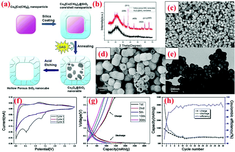 | ||
| Fig. 24 (a) Synthesis route of silica nanocubes; (b) XRD pattern, (c and d) SEM images, (e) TEM image, and (f–h) electrochemical data. Reproduced with permission.99 © 2013, Nature Publishing Group. | ||
7.2 Pomegranate-inspired silicon nanoparticles
A pomegranate-inspired nanoscale design for the silicon anode is proposed by Liu et al.15 lately. In this pomegranate microbead structure, the Si particle structure is engineered at two-length scales. First, individual Si@C yolk–shell particles are formed with sizes of ∼100 nm. Second, these yolk–shell nanoparticles are clustered together to form secondary particles of sizes 1–10 μm (Fig. 25). Such a pomegranate-inspired Si structure is synthesized through a series of processing steps including (i) coating commercial silicon nanoparticles with a SiO2 layer using the sol–gel process with TEOS as the precursor, (ii) self-assembly of Si@SiO2 nanoparticles in a water-in-oil emulsion to form the assembled Si@SiO2 clusters of 1–10 μm in diameter, (iii) heat treatment at 550 °C for 1 h in the air to remove the organics and condense the cluster structures, (iv) formation of a resorcinol–formaldehyde resin (RF) layer to wrap the Si@SiO2 cluster, which is converted into a carbon layer under argon at 800 °C, and (v) finally, the SiO2 sacrificial layer is removed with 5 wt% HF solution to form the yolk–shell structure in each individual nanoparticle.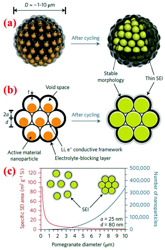 | ||
| Fig. 25 (a and b) Pomegranate design in both 3D and cross section views, (c) the specific surface area in contact with the electrolyte and the number of particles vs. pomegranate diameter. Reproduced with permission.15 © 2014, Nature Publishing Group. | ||
The advantages of this pomegranate-inspired microbead structure is that the electrolyte is blocked out of the cluster instead of forming SEI layers on each individual nanoparticle, while the void space in individual yolk–shell particles can accommodate the large volume change of silicon during the charge/discharge process. Therefore, this pomegranate-inspired design addresses three fundamental challenges faced by nanostructured electrodes simultaneously: (a) a high surface area (leading to significant SEI formation and low coulombic efficiency), (b) a low tap density (thus a low volumetric capacity), and (c) generally poor electrical properties due to the high interparticle resistance (resulting in poor cycle life). Indeed, the pomegranate microbead structure shows remarkable battery performance with a specific capacity of 2350 and 1160 mA h g−1 at C/20 and C/2 rates, respectively, after 1000 cycles (Fig. 25). Furthermore, this electrode has reached an areal capacity as high as 3.1 mA h cm−2 with a high solid loading of 3.12 mg cm−2 at the anode. To the best of our knowledge, there are only two engineered Si structures can reach an areal capacity above 3.0 mA h cm−2. The other one is the carbon-coated, graphene-supported, micro-sized porous Si.95 Both of these breakthroughs were accomplished in 2014.
7.3 Crab shell templates
To address the issues of high cost and a complex synthesis process of nanostructures, Yao et al.100 have conceived the idea of using nature available crab shell fibers as bio-templates to synthesize Si electrodes. The highly mineralized chitin-protein fibers, when removed during thermal calcination, leave a twisted plywood CaCO3 template with nanoscale channels of ∼70 nm in diameter. The CaCO3 template is then coated with a uniform carbon layer, followed by deposition of a Si layer inside the nano-channels via CVD. The CaCO3 core is subsequently dissolved while the hollow carbon nanofiber arrays are retained to encapsulate the silicon nanotube (Fig. 26). The battery made with this material shows a reversible specific capacity maintained at ∼2010 mA h g−1 after 200 cycles at the C/2 rate. The superior properties have been ascribed to the combined effects of the hollow Si nanostructure and the robust outer carbon shell. The former provides sufficient space for the volume expansion of Si during cycles, while the latter reduces deleterious interactions of the active material with the electrolyte and forces the Si to expand inwards during cycling. The high electrochemical performance of this material and the huge availability of the natural precursors promise a bright future in the field of low cost nanomaterial synthesis.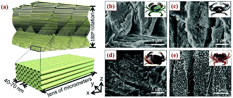 | ||
| Fig. 26 (a) Hollow nanochannels formed after removal of the organic fibers, (b–e) comparison of biotemplates prepared from different types of crab shells (Chinese hairy crab, blue crab, stone crab, and a Dungeness crab). Reproduced with permission.100 © 2013, American Chemical Society. | ||
7.4 Prelithiated Si anodes
Si nanostructures (e.g., nanoparticles, core–shell and yolk–shell nanostructures, nanowires, nanotubes, nanocomposites, etc.) can all offer improvements in cycle life over coarse Si particles. However, the drawback of these nanostructures is that their high surface area increases SEI formation in the first and later cycles. As a result, the first-cycle coulombic efficiency of Si anodes is typically low in the range of 50% to 80%.101 One method to improve the irreversible capacity loss in the first cycle is prelithiation. Zhao et al.101 have synthesized artificial SEI-protected LixSi nanoparticles via a two-step synthesis method. The prelithiation agent is able to prelithiate both alloying and intercalating type anode materials. First, the LixSi nanoparticles are prepared by mixing Si NPs and Li metal at 200 °C for 3 days under mechanical stirring to form a crystalline LixSi core. Second, the crystalline LixSi core is coated with an amorphous inert layer by reduction of 1-fluorodecane. The process is similar to the SEI formation in the battery and the coating thickness can be controlled by changing the oxidant concentration. Once the artificial SEI-coated LixSi NPs are in contact with the electrolyte, the LixSi NPs are reactivated and help improve the first cycle coulombic efficiency to 99.2%, avoiding the huge first cycle capacity loss. These artificially SEI-coated NPs eliminate lithium consumption to form a SEI layer around particles and help to solve the irreversible capacity decay problem.Prelithiation also provides the possibility of coupling prelithiated Si anodes with cathodes containing no Li (such as S cathodes). Liu et al.86 have proposed a facile method based on the self-discharge mechanism to prelithiate SiNWs. Nanowires are grown on a stainless steel substrate and a lithium foil is placed on the top of the SiNWs with the electrolyte added in between.86 Under the highly spontaneous chemical reaction (driving force, ΔG = −42 kJ mol−1), SiNWs are lithiated to 50% of their theoretical capacity within 20 minutes with little or no change in the morphology of SiNWs. The prelithiated SiNWs have been paired with a sulfur-based cathode to evaluate the effectiveness of prelithiation. The full cell can maintain ∼80% of its initial capacity after 10 cycles, but it decays with a constant slope throughout cycling. The prelithiation on SiNWs enlightened the possibility of utilizing lithium-free materials as a future lithium ion battery electrode. However, additional work is needed to optimize the performance of full cells.
Forney et al.102 have established a novel method to prelithiate silicon–carbon nanotubes (Si/CNT) using a stabilized lithium metal powder (SLMP). By prelithiating Si/CNT, the lithium introduced could compensate for the lithium consumption during the SEI formation process, and this will lead to an increase in the capacity retention, especially in the first cycle. The SLMP prelithiated Si/CNT is synthesized by SLMP deposition (drop-casting SLMP/toluene onto SI/CNT) followed by pressure activation and 40–50 h of equilibration. The pressure activation is crucial to ensure the contact and diffusion of lithium into the anode, and the equilibration helps SLMP to reach a stable state of prelithiation and achieve capacity matching between the anode and the cathode. This treatment on the Si/CNT anode has eliminated 20–40% of capacity loss in the first cycle, achieving >1000 cycles at 20% depth of discharge.
VIII. Summary and outlook
Silicon has a higher theoretical capacity (3590 mA h g−1) than other materials for Li-ion battery anodes. However, its practical application is impeded by three major challenges: large volume expansion during cycling (∼300%), low electrical conductivity, and instability of the SEI layer caused by repeated volume changes of the Si material. Significant research efforts have been devoted to addressing these challenges. The strategies studied so far include reducing particle sizes to the nanoscale, pursuing conductive coatings or conductive networks, providing void space during synthesis to accommodate volume expansion, introducing highly elastic phases to mitigate the deleterious effect of large volume changes, and a combination of these strategies.To compare the effectiveness of the different strategies investigated so far, Si material designs with the best performance obtained to date have been summarized in Table 2. The list in this table is selected based on two criteria. First, the cycle number demonstrated needs to be 100 or higher. Second, the specific capacity needs to be high (near 1000 mA h g−1) or an exceptionally long cycle life has been demonstrated (such as 6000 cycles). Several general trends can be extracted from this table. First, all of the designs, regardless of their morphology (particles, tubes, fibers, or films), use nanoscale Si as the building block to form Si anodes, demonstrating that reducing the building block to the nanoscale is essential for minimizing the volume change per particle during cycles. Second, most of the Si material designs pursue conductive coatings or introducing conductive networks to improve the electrical conductivity of the Si anode and, in some cases, to confine Si volume expansion within the conductive coatings. Third, many Si material designs with outstanding performance are associated with the introduction of void space during synthesis. In fact, only three material designs that have made their way into the list in Table 2 do not introduce void space during synthesis, and all of these designs (i.e., Si@SiOx@C, Si@SiO2@C, and Si/silicide composite) have only been cycled up to 100 cycles. In contrast, several Si material designs with engineered void space have exhibited stable cyclability up to 1000 cycles or more with high specific capacities. Finally, the best performance of Si anodes with a high specific capacity and long cycle life is attained through well-designed internal structures by combining multiple strategies including nanoscale building blocks, conductive coatings or networks, and engineered void space. The best examples of such Si material designs are pomegranate-inspired Si design15 and carbon-coated, graphene-supported, micro-sized porous Si.95 Both of these designs not only have high specific capacities with long life, but also possess high areal capacities (>3.0 mA h cm−2) at high mass loading. The latter is very important for high specific capacities at the cell level, and thus is essential for practical applications in LIBs.
| Si material design | Specific capacity after cycling (mA h g−1) | Charge–discharge cycles demonstrated | Ref. |
|---|---|---|---|
| a Only these two designs have achieved an areal capacity higher than 3.0 mA h cm−2. | |||
| Si@SiOx@C | 1450 | 100 | 40 |
| Si@SiO2@C | 785 | 100 | 43 |
| Interconnected hollow Si spheres | 1526 | 700 | 69 |
| Hollow Si@Ag core–shell structure | 3000 | 100 | 77 |
| Si@void@C yolk–shell structure | 1400 | 1000 | 12 |
| Si@void@SiO2@void@C double yolk–shell structure | 956 | 430 | 13 |
| Si@void@C yolk–shell structure | 780 | 100 | 42 |
| Nano-sized porous Si | 2200 | 100 | 17 |
| Carbon-coated, micro-sized porous Si | 1459 | 200 | 16 |
| Carbon-coated, micro-sized porous Si | 1200 | 600 | 80 |
| Carbon-coated Si nanotubes | 2700 | 200 | 81 |
| Double-walled Si nanotubes | 590 | 6000 | 89 |
| Carbon-coated, graphene-supported, micro-sized porous Si | 1150a | 100 | 95 |
| Si/silicide composite | 840 | 100 | 22 |
| Pomegranate-inspired Si design | 1160a | 1000 | 15 |
The research conducted so far has identified many effective strategies to address the issues of Si anodes, and significant advancements have been made. With continuous innovations of Si anode designs on geometric structures and trials on different combinations of functional material composites, silicon's outstanding properties as an anode material could be exploited to the most. However, the search for finding the optimized internal structure for silicon to harvest its theoretical capacity has not ended yet. Continued advancements in the following several directions will be essential for the eventual broad market penetration of Si-based LIBs, and thus we anticipate that these areas will attract significant attention in the next several years.
8.1 Si anodes with high mass loading
Anodes with high Si mass loading and high areal capacities are essential for practical applications. Well-designed anodes such as pomegranate-inspired Si design15 and carbon-coated, graphene-supported, micro-sized porous Si95 have demonstrated the possibility of achieving such a goal. However, further improvement is desired. One of the approaches to further enhance Si mass loading while improving electrochemical performance is by increasing the tap density of Si anodes. During the writing of this review, an article describing such an effort was published.103 In that article, a new method that starts with mechanical pressing of silica-coated Si nanoparticles (Si@SiO2) to produce high tap density silicon anodes is described. The mechanically pressed pellets are then subjected to thermal sintering at 600 °C for 2 h to link nanoparticles together before ball milling to form micrometer-sized powder, which is then coated with carbon to form Si@SiO2@C particles of 1–15 μm in size. The last step is etching to remove silica and provide enough empty spaces for silicon volume change. The tap density obtained by this approach is 0.91 g cm−3, about double the value of pomegranate-inspired Si design.15 The anode made using these micrometer-sized particles can have mass loading as high as 2.02 mg cm−3 with a high areal capacity of ∼3.5 mA h cm−2 at a current density of 0.1 mA cm−2. The authors also demonstrate that with the addition of carbon nanotubes to the micrometer-sized particles the rate capability can be further enhanced.8.2 Low cost synthesis and processing methods
Well-designed anodes such as pomegranate-inspired Si design15 and carbon-coated, graphene-supported, micro-sized porous Si95 have demonstrated the possibility of achieving high specific capacities with long life as well as high areal capacities (>3.0 mA h cm−2) at high mass loading. However, synthesis methods for these well-engineered Si structures are often very elaborate and, in some cases, the addition of expensive carbon nanotubes and graphene is sought. For widespread applications of high performance Si anodes the cost will eventually determine the fate of high performance Si anodes. For example, both carbon black and graphene can improve electrical conductivity, but the cost of graphene is more than 10![[thin space (1/6-em)]](https://www.rsc.org/images/entities/char_2009.gif) 000 times that of carbon black. Therefore, we expect that low cost synthesis and processing methods which are scalable at the industry setting will be an important area for research in the next several years. The latest article103 has made a significant step towards this direction.
000 times that of carbon black. Therefore, we expect that low cost synthesis and processing methods which are scalable at the industry setting will be an important area for research in the next several years. The latest article103 has made a significant step towards this direction.
8.3 Prelithiated anodes
Research conducted so far86,101,102 have clearly shown that prelithiation is an effective method to improve the irreversible capacity loss in the first cycle. Prelithiation also allows the formation of batteries by coupling of Li–Si alloy anodes with cathodes containing no Li. However, the first investigation of batteries made of a Li–Si alloy anode versus a sulfur cathode reveals that significant efforts are needed in the future to improve the cycle stability of such a battery.86 Another area that deserves attention is the integration of prelithiated Si with conductive coatings. The latter will provide three functions simultaneously: (i) serving as a highway for electron and Li-ion transport, (ii) confining Si volume changes within the conductive shell, and (iii) offering a stable interface for SEI formation and contact between particles during cycling. As the Si core has been prelithiated, the first reaction is delithiation along with volume shrinkage. This should reduce the propensity of Si cracking drastically.8.4 Self-healing binders
Although this review focuses on Si anode design, it should be pointed out that the challenges faced by Si anodes should also be addressed by advancing other components such as electrolytes and binders. Lately, Wang et al.104 have shown that the cycling stability of silicon microparticles (SiMPs) can be improved drastically by utilizing a self-healing polymer (SHP) binder. This polymer confines the SiMPs’ large volume expansion and helps to keep the contact among broken Si particles, which ensures a stable cycling performance as well as a high capacity retention. To improve the conductivity and mechanical properties of SHP, carbon black nanoparticles are consolidated in the structure of the polymer. This polymer shows superior properties compared to polyvinylidene fluoride (PVDF), carboxymethyl cellulose (CMC) and alginate binders. The first cycle discharge capacity of 2617 mA h g−1 at 0.4 A g−1 is achieved while 80% of this value is retained after 90 cycles. Recently, the same researchers have published another paper105 that reported a high areal capacity anode (3–4 mA h cm−2) with 3D distribution of SHP in the optimized Si matrix. After comparing silicon particles with different size distributions, the authors have concluded that selection of Si particle sizes and their distributions is important for full utilization of self-healing binders, and Si particles with 500 nm–1.5 μm size distribution (with 800 nm peaks) are found to exhibit the best electrochemical performance.8.5 Properties and behavior of Si in multiple cycles
In situ TEM analysis61–63 of the expansion and cracking behavior of Si pillars,64,66 and density functional theory (DFT) calculations48,60 have improved drastically our understanding of the intrinsic properties and behavior of Si under electrochemical loading. However, most of these studies have focused on the first cycle lithiation. Thus, efforts to study the intrinsic properties and behavior of Si under multiple cycles are urgently needed since all practical applications require many cycles. Fundamental understanding along this direction will provide guidelines for the rational design of Si anodes, which can pave the way for the broad market penetration of Si-based LIBs.In conclusion, we expect the design and synthesis of Si anodes to remain a very active area in the near future. By overcoming the volume expansion, low conductivity and unstable SEI problem of silicon, the best anode materials with an extremely high capacity and huge availability will be ready for a revolution of the lithium ion battery field. We are optimistic of witnessing a breakthrough in Si anode applications and the future blooming of lithium ion batteries as the energy solution for the future.
Acknowledgements
MA and LS are grateful to the Rowe Family Endowment Fund, and QH acknowledges support from a Tang Fellowship.References
- J. M. Tarascon and M. Armand, Nature, 2001, 414, 359–367 CrossRef CAS PubMed.
- D. Larcher, S. Beattie, M. Morcrette, K. Edstrom, J.-C. Jumas and J.-M. Tarascon, J. Mater. Chem., 2007, 17, 3759–3772 RSC.
- M. Obrovac and L. Krause, J. Electrochem. Soc., 2007, 154, A103–A108 CrossRef CAS.
- C. K. Chan, H. Peng, G. Liu, K. McIlwrath, X. F. Zhang, R. A. Huggins and Y. Cui, Nat. Nanotechnol., 2008, 3, 31–35 CrossRef CAS PubMed.
- L. Pan, H. Wang, D. Gao, S. Chen, L. Tan and L. Li, Chem. Commun., 2014, 50, 5878–5880 RSC.
- S. D. Beattie, D. Larcher, M. Morcrette, B. Simon and J.-M. Tarascon, J. Electrochem. Soc., 2008, 155, A158–A163 CrossRef CAS.
- M. Holzapfel, H. Buqa, L. J. Hardwick, M. Hahn, A. Würsig, W. Scheifele, P. Novák, R. Kötz, C. Veit and F.-M. Petrat, Electrochim. Acta, 2006, 52, 973–978 CrossRef CAS.
- B. Liang, Y. Liu and Y. Xu, J. Power Sources, 2014, 267, 469–490 CrossRef CAS.
- H. K. Liu, Z. Guo, J. Wang and K. Konstantinov, J. Mater. Chem., 2010, 20, 10055–10057 RSC.
- W.-J. Zhang, J. Power Sources, 2011, 196, 13–24 CrossRef CAS.
- H. Kim, M. Seo, M.-H. Park and J. Cho, Angew. Chem., Int. Ed., 2010, 49, 2146–2149 CrossRef CAS PubMed.
- N. Liu, H. Wu, M. T. McDowell, Y. Yao, C. Wang and Y. Cui, Nano Lett., 2012, 12, 3315–3321 CrossRef CAS PubMed.
- L. Y. Yang, H. Z. Li, J. Liu, Z. Q. Sun, S. S. Tang and M. Lei, Sci. Rep., 2015, 5, 10908 CrossRef CAS PubMed.
- J. Graetz, C. Ahn, R. Yazami and B. Fultz, Electrochem. Solid-State Lett., 2003, 6, A194–A197 CrossRef CAS.
- N. Liu, Z. Lu, J. Zhao, M. T. McDowell, H.-W. Lee, W. Zhao and Y. Cui, Nat. Nanotechnol., 2014, 9, 187–192 CrossRef CAS PubMed.
- R. Yi, F. Dai, M. L. Gordin, S. Chen and D. Wang, Adv. Energy Mater., 2013, 3, 295–300 CrossRef CAS.
- N. Liu, K. Huo, M. T. McDowell, J. Zhao and Y. Cui, Sci. Rep., 2013, 3, 1919 Search PubMed.
- J. Song, S. Chen, M. Zhou, T. Xu, D. Lv, M. L. Gordin, T. Long, M. Melnyk and D. Wang, J. Mater. Chem. A, 2014, 2, 1257–1262 CAS.
- G. Hwang, H. Park, T. Bok, S. Choi, S. Lee, I. Hwang, N.-S. Choi, K. Seo and S. Park, Chem. Commun., 2015, 51, 4429–4432 RSC.
- M. Li, J. Gu, X. Feng, H. He and C. Zeng, Electrochim. Acta, 2015, 164, 163–170 CrossRef CAS.
- D.-H. Lee, H.-W. Shim and D.-W. Kim, Electrochim. Acta, 2014, 146, 60–67 CrossRef CAS.
- H. K. Han, C. Loka, Y. M. Yang, J. H. Kim, S. W. Moon, J. S. Cho and K.-S. Lee, J. Power Sources, 2015, 281, 293–300 CrossRef CAS.
- M. Wu, J. E. C. Sabisch, X. Song, A. M. Minor, V. S. Battaglia and G. Liu, Nano Lett., 2013, 13, 5397–5402 CrossRef CAS PubMed.
- J. S. Kim, W. Pfleging, R. Kohler, H. J. Seifert, T. Y. Kim, D. Byun, H.-G. Jung, W. Choi and J. K. Lee, J. Power Sources, 2015, 279, 13–20 CrossRef CAS.
- N.-S. Choi, K. H. Yew, K. Y. Lee, M. Sung, H. Kim and S.-S. Kim, J. Power Sources, 2006, 161, 1254–1259 CrossRef CAS.
- A. Magasinski, B. Zdyrko, I. Kovalenko, B. Hertzberg, R. Burtovyy, C. F. Huebner, T. F. Fuller, I. Luzinov and G. Yushin, ACS Appl. Mater. Interfaces, 2010, 2, 3004–3010 CAS.
- I. Kovalenko, B. Zdyrko, A. Magasinski, B. Hertzberg, Z. Milicev, R. Burtovyy, I. Luzinov and G. Yushin, Science, 2011, 334, 75–79 CrossRef CAS PubMed.
- C. M. Hayner, X. Zhao and H. H. Kung, Annu. Rev. Chem. Biomol. Eng., 2012, 3, 445–471 CrossRef CAS PubMed.
- C.-M. Park, J.-H. Kim, H. Kim and H.-J. Sohn, Chem. Soc. Rev., 2010, 39, 3115–3141 RSC.
- J. Wen, Y. Yu and C. Chen, Mater. Express, 2012, 2, 197–212 CrossRef CAS.
- M. Ge, X. Fang, J. Rong and C. Zhou, Nanotechnology, 2013, 24, 422001 CrossRef CAS PubMed.
- D. Ma, Z. Cao and A. Hu, Nano-Micro Lett., 2014, 6, 347–358 CrossRef.
- N. Nitta and G. Yushin, Part. Part. Syst. Charact., 2014, 31, 317–336 CrossRef CAS.
- M. L. Terranova, S. Orlanducci, E. Tamburri, V. Guglielmotti and M. Rossi, J. Power Sources, 2014, 246, 167–177 CrossRef CAS.
- X. Su, Q. Wu, J. Li, X. Xiao, A. Lott, W. Lu, B. W. Sheldon and J. Wu, Adv. Energy Mater., 2014, 4, 1300882 Search PubMed.
- H. Kim, E.-J. Lee and Y.-K. Sun, Mater. Today, 2014, 17, 285–297 CrossRef CAS.
- Y. Yin, L. Wan and Y. Guo, Chin. Sci. Bull., 2012, 57, 4104–4110 CrossRef CAS.
- R. Teki, M. K. Datta, R. Krishnan, T. C. Parker, T.-M. Lu, P. N. Kumta and N. Koratkar, Small, 2009, 5, 2236–2242 CrossRef CAS PubMed.
- M. Gu, Y. He, J. Zheng and C. Wang, Nano Energy, 2015 DOI:10.1016/j.nanoen.2015.08.025.
- D. Wang, M. Gao, H. Pan, J. Wang and Y. Liu, J. Power Sources, 2014, 256, 190–199 CrossRef CAS.
- P. Zhang, L. Wang, J. Xie, L. Su and C.-A. Ma, J. Mater. Chem. A, 2014, 2, 3776–3782 CAS.
- H. Tao, L.-Z. Fan, W.-L. Song, M. Wu, X. He and X. Qu, Nanoscale, 2014, 6, 3138–3142 RSC.
- H.-C. Tao, X.-L. Yang, L.-L. Zhang and S.-B. Ni, Ionics, 2014, 20, 1547–1552 CrossRef CAS.
- T. Cetinkaya, M. Uysal, M. O. Guler, H. Akbulut and A. Alp, Powder Technol., 2014, 253, 63–69 CrossRef CAS.
- Z. Sun, X. Song, P. Zhang and L. Gao, RSC Adv., 2014, 4, 20814–20820 RSC.
- Z. Sun, S. Tao, X. Song, P. Zhang and L. Gao, J. Electrochem. Soc., 2015, 162, A1530–A1536 CrossRef CAS.
- J. Wan, A. F. Kaplan, J. Zheng, X. Han, Y. Chen, N. J. Weadock, N. Faenza, S. Lacey, T. Li, J. Guo and L. Hu, J. Mater. Chem. A, 2014, 2, 6051–6057 CAS.
- J. Rohrer, A. Moradabadi, K. Albe and P. Kaghazchi, J. Power Sources, 2015, 293, 221–227 CrossRef CAS.
- D. Wang, M. Gao, H. Pan, Y. Liu, J. Wang, S. Li and H. Ge, J. Alloys Compd., 2014, 604, 130–136 CrossRef CAS.
- M. Zhang, X. Hou, J. Wang, M. Li, S. Hu, Z. Shao and X. Liu, J. Alloys Compd., 2014, 588, 206–211 CrossRef CAS.
- T. Mori, C.-J. Chen, T.-F. Hung, S. G. Mohamed, Y.-Q. Lin, H.-Z. Lin, J. C. Sung, S.-F. Hu and R.-S. Liu, Electrochim. Acta, 2015, 165, 166–172 CrossRef CAS.
- C. Ma, C. Ma, J. Wang, H. Wang, J. Shi, Y. Song, Q. Guo and L. Liu, Carbon, 2014, 72, 38–46 CrossRef CAS.
- Y. Zhang, Y. Jiang, Y. Li, B. Li, Z. Li and C. Niu, J. Power Sources, 2015, 281, 425–431 CrossRef CAS.
- M. Su, Z. Wang, H. Guo, X. Li, S. Huang, W. Xiao and L. Gan, Electrochim. Acta, 2014, 116, 230–236 CrossRef CAS.
- D. Yan, Y. Bai, C. Yu, X. Li and W. Zhang, J. Alloys Compd., 2014, 609, 86–92 CrossRef CAS.
- R. A. Huggins, J. Power Sources, 1999, 81, 13–19 CrossRef.
- N. Liu, W. Li, M. Pasta and Y. Cui, Front. Physiol., 2014, 9, 323–350 CrossRef.
- P. Limthongkul, Y.-I. Jang, N. J. Dudney and Y.-M. Chiang, J. Power Sources, 2003, 119, 604–609 CrossRef.
- X. H. Liu, H. Zheng, L. Zhong, S. Huang, K. Karki, L. Q. Zhang, Y. Liu, A. Kushima, W. T. Liang and J. W. Wang, Nano Lett., 2011, 11, 3312–3318 CrossRef CAS PubMed.
- M. K. Y. Chan, C. Wolverton and J. P. Greeley, J. Am. Chem. Soc., 2012, 134, 14362–14374 CrossRef CAS PubMed.
- X. H. Liu, L. Zhong, S. Huang, S. X. Mao, T. Zhu and J. Y. Huang, ACS Nano, 2012, 6, 1522–1531 CrossRef CAS PubMed.
- M. T. McDowell, I. Ryu, S. W. Lee, C. Wang, W. D. Nix and Y. Cui, Adv. Mater., 2012, 24, 6034–6041 CrossRef CAS PubMed.
- X. H. Liu, J. W. Wang, S. Huang, F. Fan, X. Huang, Y. Liu, S. Krylyuk, J. Yoo, S. A. Dayeh, A. V. Davydov, S. X. Mao, S. T. Picraux, S. Zhang, J. Li, T. Zhu and J. Y. Huang, Nat. Nanotechnol., 2012, 7, 749–756 CrossRef CAS PubMed.
- S. W. Lee, M. T. McDowell, L. A. Berla, W. D. Nix and Y. Cui, Proc. Natl. Acad. Sci. U. S. A., 2012, 109, 4080–4085 CrossRef CAS PubMed.
- M. Armand and J.-M. Tarascon, Nature, 2008, 451, 652–657 CrossRef CAS PubMed.
- S. W. Lee, H.-W. Lee, I. Ryu, W. D. Nix, H. Gao and Y. Cui, Nat. Commun., 2015, 6, 7533 CrossRef CAS PubMed.
- M. Neuberger, Silicon: Electrical Conductivity Data Sheets, DTIC Document, 1963.
- M. Park, X. Zhang, M. Chung, G. B. Less and A. M. Sastry, J. Power Sources, 2010, 195, 7904–7929 CrossRef CAS.
- Y. Yao, M. T. McDowell, I. Ryu, H. Wu, N. Liu, L. Hu, W. D. Nix and Y. Cui, Nano Lett., 2011, 11, 2949–2954 CrossRef CAS PubMed.
- Y. Hwa, W.-S. Kim, S.-H. Hong and H.-J. Sohn, Electrochim. Acta, 2012, 71, 201–205 CrossRef CAS.
- T. Zhang, L. Fu, J. Gao, L. Yang, Y. Wu and H. Wu, Pure Appl. Chem., 2006, 78, 1889–1896 CrossRef CAS.
- T. Zhang, J. Gao, H. P. Zhang, L. C. Yang, Y. P. Wu and H. Q. Wu, Electrochem. Commun., 2007, 9, 886–890 CrossRef CAS.
- S. Murugesan, J. T. Harris, B. A. Korgel and K. J. Stevenson, Chem. Mater., 2012, 24, 1306–1315 CrossRef CAS.
- J. T. Harris, J. L. Hueso and B. A. Korgel, Chem. Mater., 2010, 22, 6378–6383 CrossRef CAS.
- L. E. Pell, A. D. Schricker, F. V. Mikulec and B. A. Korgel, Langmuir, 2004, 20, 6546–6548 CrossRef CAS PubMed.
- D. Tang, R. Yi, M. L. Gordin, M. Melnyk, F. Dai, S. Chen, J. Song and D. Wang, J. Mater. Chem. A, 2014, 2, 10375–10378 CAS.
- D. Chen, X. Mei, G. Ji, M. Lu, J. Xie, J. Lu and J. Y. Lee, Angew. Chem., Int. Ed., 2012, 51, 2409–2413 CrossRef CAS PubMed.
- X.-Y. Zhou, J.-J. Tang, J. Yang, J. Xie and L.-L. Ma, Electrochim. Acta, 2013, 87, 663–668 CrossRef CAS.
- X. Li, P. Meduri, X. Chen, W. Qi, M. H. Engelhard, W. Xu, F. Ding, J. Xiao, W. Wang, C. Wang, J.-G. Zhang and J. Liu, J. Mater. Chem., 2012, 22, 11014–11017 RSC.
- R. Yi, F. Dai, M. L. Gordin, H. Sohn and D. Wang, Adv. Energy Mater., 2013, 3, 1507–1515 CrossRef CAS.
- H. Kim, B. Han, J. Choo and J. Cho, Angew. Chem., Int. Ed., 2008, 120, 10305–10308 CrossRef.
- B. M. Bang, J.-I. Lee, H. Kim, J. Cho and S. Park, Adv. Energy Mater., 2012, 2, 878–883 CrossRef CAS.
- B. M. Bang, H. Kim, H.-K. Song, J. Cho and S. Park, Energy Environ. Sci., 2011, 4, 5013–5019 CAS.
- A. Magasinski, P. Dixon, B. Hertzberg, A. Kvit, J. Ayala and G. Yushin, Nat. Mater., 2010, 9, 353–358 CrossRef CAS PubMed.
- J.-I. Lee, N.-S. Choi and S. Park, Energy Environ. Sci., 2012, 5, 7878–7882 CAS.
- N. Liu, L. Hu, M. T. McDowell, A. Jackson and Y. Cui, ACS Nano, 2011, 5, 6487–6493 CrossRef CAS PubMed.
- M.-H. Park, M. G. Kim, J. Joo, K. Kim, J. Kim, S. Ahn, Y. Cui and J. Cho, Nano Lett., 2009, 9, 3844–3847 CrossRef CAS PubMed.
- Z. Wen, G. Lu, S. Mao, H. Kim, S. Cui, K. Yu, X. Huang, P. T. Hurley, O. Mao and J. Chen, Electrochem. Commun., 2013, 29, 67–70 CrossRef CAS.
- H. Wu, G. Chan, J. W. Choi, I. Ryu, Y. Yao, M. T. McDowell, S. W. Lee, A. Jackson, Y. Yang, L. Hu and Y. Cui, Nat. Nanotechnol., 2012, 7, 310–315 CrossRef CAS PubMed.
- C. Zhang, L. Gu, N. Kaskhedikar, G. Cui and J. Maier, ACS Appl. Mater. Interfaces, 2013, 5, 12340–12345 CAS.
- T. H. Hwang, Y. M. Lee, B.-S. Kong, J.-S. Seo and J. W. Choi, Nano Lett., 2011, 12, 802–807 CrossRef PubMed.
- H. Wu, G. Zheng, N. Liu, T. J. Carney, Y. Yang and Y. Cui, Nano Lett., 2012, 12, 904–909 CrossRef CAS PubMed.
- Z. Du, S. Zhang, Y. Liu, J. Zhao, R. Lin and T. Jiang, J. Mater. Chem., 2012, 22, 11636–11641 RSC.
- B.-S. Lee, S.-B. Son, K.-M. Park, J.-H. Seo, S.-H. Lee, I.-S. Choi, K.-H. Oh and W.-R. Yu, J. Power Sources, 2012, 206, 267–273 CrossRef CAS.
- R. Yi, J. Zai, F. Dai, M. L. Gordin and D. Wang, Nano Energy, 2014, 6, 211–218 CrossRef CAS.
- L. Shao, J. Shu, K. Wu, X. Lin, P. Li, M. Shui, D. Wang, N. Long and Y. Ren, J. Electroanal. Chem., 2014, 727, 8–12 CrossRef CAS.
- F.-S. Li, Y.-S. Wu, J. Chou and N.-L. Wu, Chem. Commun., 2015, 51, 8429–8431 RSC.
- Z. Guo, J. Wang, H. Liu and S. Dou, J. Power Sources, 2005, 146, 448–451 CrossRef CAS.
- N. Yan, F. Wang, H. Zhong, Y. Li, Y. Wang, L. Hu and Q. Chen, Sci. Rep., 2013, 3, 1568 Search PubMed.
- H. Yao, G. Zheng, W. Li, M. T. McDowell, Z. Seh, N. Liu, Z. Lu and Y. Cui, Nano Lett., 2013, 13, 3385–3390 CrossRef CAS PubMed.
- J. Zhao, Z. Lu, H. Wang, W. Liu, H.-W. Lee, K. Yan, D. Zhuo, D. Lin, N. Liu and Y. Cui, J. Am. Chem. Soc., 2015, 137, 8372–8375 CrossRef CAS PubMed.
- M. W. Forney, M. J. Ganter, J. W. Staub, R. D. Ridgley and B. J. Landi, Nano Lett., 2013, 13, 4158–4163 CrossRef CAS PubMed.
- D. Lin, Z. Lu, P.-C. Hsu, H. R. Lee, N. Liu, J. Zhao, H. Wang, C. Liu and Y. Cui, Energy Environ. Sci., 2015, 8, 2371–2376 CAS.
- C. Wang, H. Wu, Z. Chen, M. T. McDowell, Y. Cui and Z. Bao, Nat. Chem., 2013, 5, 1042–1048 CrossRef CAS PubMed.
- Z. Chen, C. Wang, J. Lopez, Z. Lu, Y. Cui and Z. Bao, Adv. Energy Mater., 2015, 5, 1401826 Search PubMed.
| This journal is © The Royal Society of Chemistry 2016 |
