Biomimetic supported membranes from amphiphilic block copolymers†
Serena
Belegrinou‡
a,
Jan
Dorn‡
b,
Max
Kreiter
b,
Katarzyna
Kita-Tokarczyk
a,
Eva-Kathrin
Sinner
bc and
Wolfgang
Meier
*a
aUniversity of Basel, Department of Chemistry, Basel, Switzerland. E-mail: wolfgang.meier@unibas.ch
bMax Planck Institute for Polymer Research, Mainz, Germany
cInstitute of Materials Research and Engineering, IMRE, 3 Research Link, 117602 Singapore
First published on 4th November 2009
Abstract
A unique combination of surface chemistry and self-assembly of amphiphilic block copolymers was employed to obtain—for the first time—solid-supported biomimetic polymer bilayers. An organized monolayer from sulfur-functionalized poly(butadiene)-b-poly(ethylene oxide) was covalently attached to ultrasmooth gold upon Langmuir-Blodgett transfer. Hydrophobic interactions, on the other hand, were exploited to attach the second monolayer. As a result, we obtained a homogeneous hydrophilic-hydrophobic-hydrophilic structure, similar to supported lipid bilayers by architecture, stability and fluidity. Our polymer bilayers, however, outperform such lipid membranes with regard to tunability of thickness and stability in gaseous environments.
As characterized by surface analysis tools (AFM, SPR), solid-supported polymer membranes are smooth with a thickness of ca. 11 nm, resistant to rinsing with aqueous solutions and stable upon drying and rehydration. These properties could be attractive for nanotechnological applications, such as immobilization of functional molecules or nanoparticles, sensor development or preparation of chemically responsive functional surfaces.
Introduction
Native biological membranes are highly complex since multiple chemical and structural processes occur simultaneously, such as in cellular differentiation, growth, and interactions with the environment. To break down this complexity for direct investigations of membrane-related processes on a molecular level, the development of simplified model systems is necessary. Such membrane models offer great potential in fundamental scientific research, especially for investigating the structure and function of membrane proteins. They are also highly relevant for technological applications, including sensor technologies.In the past decades, various attempts were made to design simple and stable membrane model systems.1 In particular, solid-supported phospholipid membranes are promising, as they are superior to e.g. black lipid membranes or vesicles, in terms of stability and applicability of surface analytical techniques.2–4 Early concepts of supported membranes comprised the direct deposition of phospholipid bilayers onto solid substrates by vesicle fusion.5,6 More recent attempts involved the introduction of spacer units like peptides, oligomers, or polymers, which ensure membrane decoupling from the substrate, in order to reduce membrane-substrate interactions7–12 and create a reservoir for analytes and ions. Still, for many applications, these membrane systems do not possess sufficient stability.
An alternative to lipid membranes are systems which consist of amphiphilic block copolymers. With a certain molar mass and hydrophilic to hydrophobic block ratio, they adopt a bilayer structure in water.13,14 Polymer synthesis allows for the adjustment of such parameters as block length, molecular weight, chemical composition, hydrophilic/hydrophobic balance, and molecular architecture. This provides new insights to control amphiphilic self-assembly and produce structures of defined morphology, molecular packing, and membrane thickness. Hence, manifold possibilities are accessible for engineering customized block copolymer membranes.15–17
Measurements carried out on vesicular systems showed that these polymeric membranes exhibit up to ten times higher stability, as defined by the maximal areal strain, than lipid membranes.18 Partial interpenetration of the individual membrane layers can contribute to enhanced mechanical stability of polymeric membranes compared to lipid membranes. On the other hand, Lee et al.19 showed that there seems to be a critical chain length above which strong entanglement and high interpenetration of the layers starts to occur. Below that length, the two membrane sheets are rather separated layers standing on top of each other. This was also confirmed by simulations which show that the hydrophobic length determines the degree of entanglement of opposing chains.20
Furthermore, superstructures from amphiphilic block copolymers resemble the ones from lipids and they are suitable to functionally incorporate membrane proteins. Meier and co-workers21,22 succeeded in functionalizing triblock copolymer vesicles with the channel protein, outer membrane protein F (OmpF). However, for many analytical techniques it is highly desirable to confine membrane processes to the surface. Therefore, the development of solid-supported biomimetic polymer membranes is required. So far, the closest achievements have been solid-supported amphiphilic polymer membranes from different methacrylate-based triblock copolymers prepared by vesicle fusion23 or a grafting-from approach.24 These systems showed the characteristic hydrophilic-hydrophobic-hydrophilic structure resembling biological membranes, however the polymer chains in the surface-grafted membranes are very densely packed, and thus exhibit low fluidity, which might not be suitable for protein incorporation. The polymeric membranes prepared by vesicle fusion have a polycationic character, which might be unfavourable for protein insertion as well.
The challenge of this work was to prepare a supported polymer bilayer, by combining covalent attachment of a self-organized macromolecular film to a solid support with hydrophobic interactions between two individual bilayer leaflets. The stronger interactions between the individual polymeric leaflets and with the substrate are expected to enhance membrane stability. On the other hand, the non-covalent interactions allow for a certain degree of membrane fluidity, which is necessary for biological applications. These improvements regarding the stability and fluidity of polymeric membranes might open pathways towards architectures, which are stable in gaseous environments and generally more robust than the so far most commonly used phospholipid-based membrane models.
Our approach towards solid-supported biomimetic membranes uses amphiphilic diblock copolymers as building blocks. The polymers employed consist of hydrophobic poly(butadiene) (PB) units covalently linked to sulfur-functionalized hydrophilic poly(ethylene oxide) (PEO) blocks, which allows the application of the well-established gold/sulfur chemistry for surface-immobilization.25,26 PB-PEO block copolymers were chosen, as they were previously shown to produce fluid vesicular membranes27,28 and monolayers at the air-water interface.29,30 It was also shown that vesicles from PB-PEO do not exhibit toxic effects on living cells27 and are able to host membrane-active peptides.31
Here we present a combination of sequential Langmuir-Blodgett (LB) and Langmuir-Schaefer (LS) monolayer transfer techniques to deposit individual polymeric monolayers on ultrasmooth gold supports. The resulting structures were analysed by contact angle measurements, atomic force microscopy, and surface plasmon resonance spectroscopy to gain insights into the morphology, homogeneity, and thickness of the layers.
Experimental section
Polymer synthesis, functionalization and characterization are described in the ESI.† Here we concentrate on experimental details concerning membrane preparation and characterization.Gold substrate preparation
Ultrasmooth template stripped gold (TSG) surfaces were prepared according to a procedure previously described by Naumann et al.32 where 50 nm thin gold films were deposited by electrothermal evaporation (0.8–1 Å s−1; 5 × 10⁻⁶ mbar) on clean silicon wafers (CrysTec, Germany) and glued with epoxy glue (EPO-TEK 353ND4, USA) to clean microcrown glass slides (Menzel, Germany). The glued slides were cured for 1 h at 150 °C and stored until use.Surface pressure-area isotherms
Monolayers were investigated with a KSV 2000 Langmuir Teflon™ trough (KSV Instruments, Finland), area 420 cm2, equipped with two symmetric, hydrophilic Delrin™ barriers and a Wilhelmy plate (ashless filter paper strips, perimeter 23 mm) to monitor the surface pressure with an accuracy of 0.1 mN m−1. The trough was placed in a plastic cabinet to prevent dust contamination. All experiments were carried out in an air-conditioned lab (20 °C). Monolayers were spread drop-wise on an ultrapure water (18.2 MΩ m; Millipore, Germany) surface from chloroform solutions (typically 1–2 mg mL−1). The solvent was allowed to evaporate for 15 min, and the monolayers were compressed at a rate of 1 mm min−1.Monolayer transfer
Lipoic acid (LA) functionalized monolayers (PB-PEO-LA) were transferred onto TSG substrates by the Langmuir-Blodgett (LB) technique, using a KSV 5000 (KSV Instruments, Finland) Langmuir Teflon™ trough (area 1860 cm2), placed on an antivibrational table in a plastic cabinet.Prior to film spreading, four freshly cleaved TSG substrates were immersed in the subphase using a dipper. After compressing the film to a pressure of 35 mN m−1 it was left for 15 min in order for the polymer chains to establish their most favourable orientation. Afterwards, a monolayer film was transferred at constant speed (0.3 mm min−1) on the dipper upstroke.
Two PB-PEO-LA coated slides were used for surface investigations and the other two were subjected to a second monolayer transfer, completing the bilayer membrane. In this way, nearly identical conditions were created for one set of samples.
Bilayer preparation
A compressed PB-PEO-OH film (target pressure 35 mN m−1) was produced at the air-water interface. PB-PEO-LA coated slides were placed in the dipper horizontally above the floating monolayer. At a constant dipper speed (50 mm min−1), the substrate was lowered through the interface. The water surface was thoroughly cleaned and the gold slides were placed, under water, into a crystallization dish.Mono- and bilayer characterization
Contact angle measurements of the covalently attached monolayer were performed by applying the static sessile drop method with a fully computer-controlled instrument (DSA 10, Krüss, Germany). The measurements were carried out under ambient conditions and constant drop size (3 μL). Ultrapure water was used as the medium.Surface plasmon resonance (SPR) spectroscopy was performed using a home-built setup in the Kretschmann configuration with a He/Ne laser (λ = 633 nm).33 In scan mode, reflectivity was monitored as a function of the incident angle. In kinetic mode, reflectivity changes occurring at a fixed angle were recorded as a function of time. In order to achieve the high in-plane wave vectors of the exciting light at moderate coupling angles, the microcrown slide was attached to a LaSFN9 prism (n = 1.845). Spectra were analyzed using a four layer model, including the prism, gold, mono- or bilayer, and the surrounding medium (water or air). A refractive index n = 1.5 was assumed for both, mono- and bilayer.34 Further information regarding data evaluation is provided in the ESI.†
Atomic force microscopy (AFM) was carried out on a Nanowizard (JPK Instruments, Germany), installed on an inverted microscope (Axiovert; Zeiss, Germany). Measurements were performed in intermittent contact mode in a liquid environment. For imaging and force distance measurements, oxide-sharpened silicon nitride tips (NP–S; Veeco Instruments, Germany) with a nominal spring constant of 0.32 N m−1 were used, whereas for scratching experiments, silicon cantilevers (OMCL-AC240TS; Olympus, Germany) with a nominal spring constant of 2 N m−1 were utilized. Typical scan rates ranged from 0.8 to 1.2 Hz. Cantilevers were not calibrated for force distance measurements; the nominal spring constant was chosen.
Results and discussion
Polymer functionalization
The functionalization of the amphiphilic diblock copolymer PB-PEO-OH under classical esterification conditions with lipoic acid (LA) provided an easy synthesis route to a sulfur-functionalized polymer with 86% yield (see Fig. S2, ESI†). As the sulfur is integrated as disulfide in a dithiolane ring, no special precautions have to be taken and handling is much easier than with the more sensitive free thiols. A similar approach was used for tethering the phospholipids to ultrasmooth gold substrates.10Two-dimensional diffusion ordered spectroscopy (DOSY) was used to prove the covalent linkage of PB-PEO-OH to all the lipoic acid present in the system after the work-up procedure. The diffusion coefficients ascribed to distinct signals from the polymer backbone and the lipoic acid end-group are in the same order of magnitude, indicating the same diffusion behaviour for backbone and end-group, respectively, in the applied field gradient. Thus, end-functionalization of the polymer was successful. Diffusion coefficients and further analytical results are summarized in Table 1.
| Polymer formula | M n /g mol−1a | PDIb | DF%c | δ PBPEO/m2 s−1d | δ LA/m2 s−1d |
|---|---|---|---|---|---|
| a Number average molecular weight calculated from GPC and 1H-NMR. b PDI (polydispersity index) obtained from GPC. c DF (degree of functionalization) calculated from 1H-NMR. d δ (diffusion constants) obtained from DOSY measurements. The subscripts are assigned to clearly identified peaks of the polymer backbone (PB-PEO) and the functional group (LA), respectively. | |||||
| PB52PEO29–OH | 4100 | 1.07 | |||
| PB52PEO29–LA | 4300 | 1.09 | 86 | 2.16 × 10⁻¹⁰ | 2.18 × 10⁻¹⁰ |
Monolayers at the air-water interface
The Langmuir monolayer behaviour of the amphiphilic diblock copolymers used in this work, i.e. PB-PEO-OH and PB-PEO-LA, is characterized by surface pressure-area (π-A) isotherms. The isotherms are reproducible and reversible. Additionally, polymer organization at the air-water interface was investigated by Brewster angle microscopy (BAM). The observed monolayers were smooth and did not show any significant features over the whole compression range.Representative isotherms, recorded at 20 °C on ultrapure water as the subphase, are presented in Fig. 1 (A: PB-PEO-OH, B: PB-PEO-LA). Unlike low molecular weight amphiphiles, polymers usually do not display clear, well-defined phase transitions.35 In order to gain deeper insight into possibly occurring transitions, compressibility moduli Cs−1 = −A(∂π/∂A)T were calculated, using the first order derivatives of the isotherms.36
 | ||
| Fig. 1 Surface pressure (π) and compressibility modulus (Cs−1) versus mean molecular area for the OH-terminated polymer (A) and the lipoic acid functionalized block copolymer (B). The isotherms were recorded at T = 20 °C. I, II, and III are explained in the text. | ||
At low surface pressures and mean molecular areas >800 Å2 (I) it is assumed that the polymer films are in an expanded state (“pancake” conformation), with the hydrophobic PB blocks lying flat at the air-water interface. The insoluble PB chains are anchored to the interface by water-soluble PEO blocks. The PEO segments are assumed to adopt a flattened conformation at the interface.37 In this relaxed state, no difference in the π-A-isotherms of the two polymers is recognizable.
Upon compression, an increase in the surface pressure and compressibility modulus of both polymers is measured (II), indicating that the films undergo a transition from a gas-like to a more condensed phase. The maxima of the compressibility moduli of both polymers in this phase were calculated to be 21 mN m−1, corresponding to liquid expanded regimes.38 At smaller mean molecular areas, approximately 380 Å2 for the OH-terminated polymer (Fig. 1A) and 485 Å2 for the LA-terminated polymer (Fig. 1B), a second phase transition is revealed, as characterized by stagnating Cs−1 values. These phase transitions do not show any temperature dependence in the range from 14 to 28 °C, which means that the observed transitions are related to conformational rearrangements of the PEO blocks in the subphase rather than to first order phase transitions. As reported before,37 such transitions are assigned to the dissolution of the PEO blocks in the subphase. In this region, the PEO blocks extend into the subphase increasing intermolecular interactions by hydrogen bonding37 while the water-insoluble PB blocks serve as an anchor to the interface. This “pseudo-plateau” region becomes more pronounced with increasing PEO block length.30,37,39 The block copolymers used in this work bear only 29 PEO units, and therefore the plateau is not clearly visible. However, the first derivative of the isotherms reveals constant Cs−1 region with proceeding partial PEO dehydration.
Further compression leads to a slightly less compressible, i.e. liquid-like, phase with similar Cs−1 values for both polymers (III). At a mean molecular area of 100 Å2, the compressibility moduli of 30 mN m−1 for the OH-terminated polymer and 26 mN m−1 for the LA-terminated polymer, respectively, suggest a qualitatively similar organization pattern for the two polymers. Finally, the surface pressure of both polymers increases steeply until the films collapse at 44 mN m−1.
In order to create defect-free bilayers by consecutive Langmuir-Blodgett/-Schaefer film deposition, film stability is crucial. Therefore, the polymer monolayers were compressed to the surface pressure applied in the transfer experiments, which was monitored over time. The compressed monolayers maintained the pressure for longer than 100 min, which was the usual duration for the transfers, indicating high film stability.
Monolayers on gold
Covalent immobilization of sulfur-containing PB-PEO-LA monolayers was accomplished by LB transfer. A major advantage of the LB transfer technique is the ability to produce highly ordered monolayers without multilayer formation or major defects on very large scales compared to the size of its components. It has been applied for the controlled fabrication of highly ordered monomolecular films40 and has been successfully employed for lipid bilayer preparation.6,41,42Film depositions (Scheme 1A) were performed at the surface pressure of 35 mN m−1, which corresponds to 80% of the collapse pressure. The corresponding compressibility modulus of the monolayer is 26 mN m−1. In this phase, the polymer films assume the most densely packed brush-like order. The transfer ratios are approximately 1.3. Since the transfer ratio is an approximate indication of the transfer quality,43 our moderately deviating value from unity is acceptable and suggests successful monolayer transfer.
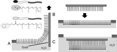 | ||
| Scheme 1 Monolayer and bilayer formation: In (A), the substrate is covalently coated with a monolayer of sulfur-functionalized polymer on the dipper upstroke. (B) and (C) show the Langmuir-Schaefer transfer by pressing the monolayer through the air-water interface. | ||
In order to follow the surface functionalization process, contact angle measurements were carried out on the bare gold surface and the transferred LB film. Contact angles increased from 60° for freshly cleaved gold substrates to at least 90° for the PB-PEO-LA-covered substrates. The contact angle values were obtained from at least five different individual measurements on the same sample. The changes towards higher values stem from the hydrophobic poly(butadiene) blocks facing away from the gold surface.
Monolayer formation was also characterized by surface plasmon resonance spectroscopy (SPR). This optical method allows for non-invasive thin film characterization and is very sensitive to small changes in adsorbed mass. A major advantage of this technique is the label free detection. Fig. 2 shows the representative angular spectrum of a PB-PEO-LA monolayer transferred to an ultrasmooth TSG substrate, a blank gold substrate, and a bilayer. The bilayer spectrum will be discussed later.
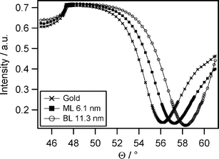 | ||
| Fig. 2 A representative angular SPR spectrum measured in ultrapure water showing the shift of the reflectivity minimum from blank gold to the covalently attached PB-PEO-LA monolayer (ML) and to the bilayer (BL). Curves were fitted using a refractive index for the polymer film of n = 1.5 (fit parameters: glass: εreal = 3.39; gold: εreal = −13.2759, εimag = 2.3799, d = 50.48 nm; polymer: εreal = 2.25; water: εreal = 1.77). | ||
The shift of the reflectivity minimum from the blank gold to the PB-PEO-LA monolayer is clearly visible in Fig. 2. From Fresnel equation-based calculations, the optical thickness of the monolayer can be obtained. Assuming a refractive index of 1.5 for the block copolymer, a mean geometrical thickness of 6.1 ± 0.4 nm was calculated. The experiments were performed in air as well as in water and data analysis resulted in the same monolayer thickness which means that neither strong swelling nor drying alters the monolayer. We note that SPR yields average mass thicknesses, meaning that it cannot distinguish rough or patchy films from plane layers.
To study local film morphology, AFM was applied for monolayer characterization. Information about homogeneity, structural defects, and roughness of the monolayers can be obtained by this method. AFM measurements were performed in air as well as in aqueous media. A typical height image and cross section of a measurement in water are presented in Fig. 3. The film surrounding the square in the centre of the image is completely unperturbed, while the part in the middle was scratched with the AFM-tip. The unaltered film does not show any defects on the micrometer scale. Roughness (root-mean-square) does not exceed 0.5 nm over one square micrometer. We note that there is a small amount of material adsorbed on top of the monolayer, which might result from impurities during film transfer. What can be seen as well is the monolayer film exhibiting a very fine structure on the length scale of about 10 nm. This might be due to rearrangements of amphiphilic polymers with chain lengths comparable to the size of these microstructures. This is not surprising since the image was recorded in water so that the hydrophobic poly(butadiene) chains tend to minimize their free energy by rearranging on the surface. However, the freedom to reorientate is limited by the covalent attachment to the substrate. AFM scratching experiments show that the monolayer cannot be scratched away, but some loosely bound material is wiped away by the tip. This loose material is likely to stem from impurities during film transfer. The dark stripes in the image are cracks in the epoxy-glue underneath the gold which result from cutting large substrates into halves.
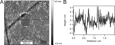 | ||
| Fig. 3 An AFM image (A), recorded in water, and corresponding cross section (B) of the covalently immobilized monolayer which was scratched with a hard cantilever. The two dark stripes result from cracks in the epoxy glue due to cutting the slide prior to monolayer transfer. | ||
Bilayer membranes on Au
The Langmuir-Schaefer (LS) technique was applied for the transfer of the second monolayer to the PB-PEO-LA-covered substrate in order to obtain a complete bilayer membrane. The procedure is depicted in Scheme 1B and C. A substrate, which had been previously coated with a PB-PEO-LA monolayer, was placed horizontally above a PB-PEO-OH Langmuir film and subsequently pressed through the air-water interface. After transfer, the sample was assembled in the measurement cell and kept hydrated throughout all surface analysis. SPR measurements were performed to investigate the thickness. The angular scans in Fig. 2 show the shift of the reflectivity minimum upon bilayer deposition with respect to the blank gold substrate. From the fit, we obtain a mean bilayer thickness of 11.3 ± 0.5 nm, assuming n = 1.5. The doubling of the layer thickness suggests a bilayer structure of the type hydrophilic-hydrophobic-hydrophilic, as depicted in Scheme 1C. The bilayer thickness is in good agreement with results reported earlier,18 where a PB-PEO diblock copolymer was investigated, having similar molecular weight and a comparable hydrophilic to hydrophobic block ratio to the polymer reported here. Bermudez et al.18 investigated the vesicular membrane thickness by cryo-TEM and the value of 9.6 nm was obtained. Considering the different membrane preparation methods, resulting in different polymer chain packing densities in vesicles vs compressed monolayers, the minor discrepancies are negligible. In the case of our planar bilayers, the chains were forced to stretch by compression at the air-water interface, whereas packing in vesicles occurs without area constraints, leading to less stretched polymer chains. Furthermore, the thickness measurements in our work consider the whole polymer length including the hydrophilic blocks and not only the hydrophobic core (as measured by cryo-TEM), which results in higher values for the thickness.The attachment of the second layer to the previously immobilized monolayer is governed mainly by hydrophobic interactions between the poly(butadiene) blocks. The resulting membrane architecture is supposed to be an intermediate structure between completely unperturbed chains, as is the case with low molecular weight amphiphiles, and an interdigitated structure.14,44 However, we expect minor entanglement of the individual polymer chains in the opposing leaflets due to the rather low molecular weight of the polymer.
Homogeneity and roughness of the respective membranes were investigated by AFM measurements in water. The height image presented in Fig. 4A shows a uniform and homogeneous bilayer. Sections across the image (Fig. 4B) and statistical analysis proved the root-mean-squared roughness to be approximately 0.35 nm over an area of 1 μm2. High uniformity and smoothness were accomplished on large areas up to several tens of square millimetres.
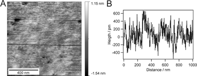 | ||
| Fig. 4 An AFM image of the intact bilayer after Langmuir-Schaefer transfer (A) and the corresponding cross section (B) shows homogenous transfer over an area of 1 μm2 with negligible defects. | ||
In addition to the height images, force–distance curves provide information about the mechanical properties. By repeatedly approaching and retracting the cantilever from the surface, adhesive and repulsive forces yielding information about structural details can be obtained. All force measurements were performed with a bare oxide-sharpened silicon nitride AFM tip, which is known to be hydrophilic. Since structures, such as presented in this work, have not been reported so far, there are no literature references concerning the force curves to compare. However, a lot is known about force measurements on supported lipid bilayers.45 For the monolayer one does not expect any characteristic features since the covalently bound polymer chains have only very limited ability to reorganise upon perturbation by the cantilever. Also the hydrophilic cantilever should be repelled from the hydrophobic surface. This exact behaviour can be seen in Fig. 5A.
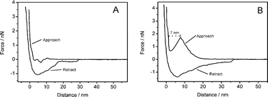 | ||
| Fig. 5 Force–distance curves measured on the monolayer (A) and the bilayer (B). Measurement on the bilayer shows a distinct jump in the approach curve which indicates the penetration of a distinct layer. Both measurements were performed using the same cantilever. | ||
In the case of the bilayer the situation is different, as shown in Fig. 5B. The molecules of the top layer tend to reorganise when the tip penetrates the surface. Since there is a lateral pressure within the membrane plane that has to be overcome, a rise of the force curve can be observed at the beginning. At a certain point, the applied force is high enough and the cantilever snaps into the bilayer, which can be seen at a distance below 10 nm where the force temporarily decreases until the lower part of the substrate is reached. This characteristic step has been observed for various supported lipid bilayer systems.45 The jump in the force–distance curve appears even after several tens of approach-retract cycles which shows that the polymer chains are mobile enough to cure the small hole made by the cantilever. The width of the jump corresponds to approximately 7 nm, which is the thickness of an individual polymer layer. Since the cantilever was not calibrated and the nominal spring constant was taken for scaling, it was not possible to determine absolute force values from these measurements. However, a qualitative statement can be made.
Scratching experiments
In order to prove the presence of the second polymer monolayer, scratching experiments were performed with a hard cantilever, able to remove material from the surface. Fig. 6A clearly shows that the upper layer can be selectively removed from the surface which is not possible by scratching the covalently attached monolayer (see Fig. 3). The corresponding section (Fig. 6B) shows the height difference between monolayer and bilayer more evidently. The formation of a well with a homogeneous depth indicates complete removal of the second layer. However, as shown in Fig. 6B, the section depth of the trace is merely 3 nm. The hard cantilever (2 N m−1) used for this experiment is not able to map the actual height, but partially penetrates the membrane. Unfortunately, it is not possible to exchange the hard tip with a soft one without losing the position of the scratch under the microscope. If a soft cantilever (with a spring constant of 0.32 N m−1) is used to image the scratched area, the expected monolayer thickness of approximately 6 nm will be found. The time span between scratching and imaging of the whole area of 2 × 2 μm is about 3 min. This time does not allow the closure of the created defect of 500 × 500 nm which points to a low chain mobility of the top layer on these large length scales.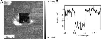 | ||
| Fig. 6 An AFM image after a scratching experiment (A) and a section through A along the indicated line (B). | ||
Membrane stability
In order to probe stability, the membrane was thoroughly rinsed with ultrapure water (18.2 MΩ m) in a flow cell and SPR reflectivity changes vs time at the incident angle of 56° were investigated. For that, the membrane was permanently kept under water. This kinetic measurement did not reveal any significant changes in reflectivity upon the harsh rinsing process. Consequently, no loss of mass was detected and the membrane stayed intact during and after the rinsing procedure. When rinsing was carried out using a good solvent for the PB-PEO diblock, such as THF or chloroform, the non-covalently bound upper leaflet of the membrane was washed away and the reflectivity minimum returned to the value obtained for a monolayer (see Fig. S3, ESI†).Furthermore, we wanted to study membrane stability in air. Therefore, the membrane was dried under a stream of nitrogen, left dry for two hours, and later rehydrated with ultrapure water. SPR measurements revealed hardly any shift of the reflectivity minimum after drying and rehydration of the membrane (see Fig. S4, ESI†). This indicates that the material adsorbed on the surface was not removed during this experiment. In addition to the optical measurements, AFM images in Fig. 7A show that the architecture does not change significantly upon drying for short times of up to two hours. This unambiguously proves the high stability of the polymer architecture compared to common lipid systems. Usually, supported and tethered lipid bilayers decompose directly when brought into contact with air, whereas solid-supported phospholipid systems resisting a rinsing procedure have already been reported.46,47 So far, the closest attempts towards air-stable supported lipid bilayers employed the stabilising effect of sugars48 or polymer layers.49 However, these approaches have the drawback of potentially hindering the access of proteins or substrates to the membrane. A recent publication from Deng et al.50 describes an air stable membrane tethered via cholesterol anchor groups which remains fluid after several cycles of drying (2 h) and rehydration.
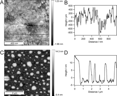 | ||
| Fig. 7 AFM images of the supported polymer bilayer after different drying stages: after 1.5 h of drying (A) with the corresponding section (B), and after 12 h of drying (C) with the corresponding section (D). | ||
Drying of our polymeric bilayer for longer than 12 h leads to a significant change in morphology, as can be seen in Fig. 7C. Objects of 10–20 nm in height are present everywhere on the surface, which suggests the disassembly of the architecture. This is most likely to be due to the polymer chains reassembling into micellar structures in order to minimize their energy. This assumption is supported by the measured height of these objects, which is within the dimensions of a complete bilayer. Consequently, we conclude here, that water is still necessary to stabilize the bilayer structure on a long term scale.
An explanation for this observation could be an insufficient coupling between the two individual polymer layers. This suggests a rather low entanglement of the polymer chains. This is in accordance with the literature for the particular chain length of the polymers used here.19 Membrane stability to drying can probably be increased by using longer block copolymers. In this case, a higher degree of interdigitation between the two opposing leaflets, thus enhanced membrane stabilization, is expected. On the other hand, a higher degree of entanglement and an increase in thickness, due to the use of longer polymers, might minimize fluidity and hinder the incorporation of proteins. This is disadvantageous for the principal purpose of this membrane system, i.e. serving as matrix for protein incorporation.
Summary
Herein we present a novel planar membrane system composed of the amphiphilic diblock copolymer, poly(butadiene)-b-poly(ethylene oxide). A standard chemical modification procedure yielded a sulfur-functionalized polymer, which could be covalently attached to ultrasmooth gold substrates by the well-controllable Langmuir-Blodgett monolayer transfer technique. The covalent attachment of the proximal membrane layer to the solid support endows the system with mechanical stability. The second layer was transferred by the Langmuir-Schaefer method and led to an artificial membrane system consisting of two individual layers, resembling the hydrophilic-hydrophobic-hydrophilic structure of lipid membranes. A certain degree of mobility results from non-covalent coupling of the individual sheets. SPR results indicated a bilayer thickness of 11.3 nm and AFM measurements proved the flatness and homogeneity of the system on several square millimetres. For the first time, a polymeric planar bilayer of defined morphology, molecular packing, and membrane thickness was produced by this straightforward preparation route. Drying experiments implied air stability of the system to a certain extent, however, the presence of water is still required to hydrate and stabilize the layered structure in the long term. The polymer used in this work falls into the regime where entanglement between opposing layers only starts to occur, which is in agreement with reports from literature for this chain length. Therefore, the stability of this membrane system could be improved by using longer, thus stronger interpenetrating, polymers. In addition, a mixture of di- and triblock block copolymers could be used as membrane building blocks. Due to their molecular structure (i.e. hydrophilic blocks on both ends of the hydrophobic core), a fraction of the triblocks will span a membrane, thus, further contribute to membrane stability. Nevertheless, the results presented in this work already suggest superior stability of our membranes compared to conventional phospholipid bilayers.These stable and robust solid-supported polymeric membranes could be a suitable platform to study membrane proteins in a completely artificial environment. Moreover, they offer versatility concerning the application of surface-analytical techniques which might lead to sensing applications in the future.
Acknowledgements
This work was supported by the NEST project 043431 (FuSyMEM), the NCCR-Nanosciences, the Swiss National Science Foundation, and the Fonds der chemischen Industrie (Kekulé fellowship to S. B.).The authors thank Dr Daniel Häussinger for the measurements of the DOSY spectra, Sven Kasper for his assistance with the synthesis, Dr Violeta Malinova for useful input into the polymer functionalization, Uwe Rietzler and Dr Rüdiger Berger for their technical support with the AFM, and Dr Inga Vockenroth, Dr Ingo Köper, Dr Mathieu Jung, Slavoj Kresak, and Dr Indriati Pfeiffer for plenty of helpful and advisory discussions. We also thank Ruth Pfalzberger for her help with the preparation of the graphics.
References
- H. Ringsdorf, B. Schlarb and J. Venzmer, Angew. Chem., Int. Ed. Engl., 1988, 27, 113–158 CrossRef.
- E. Sackmann, Science, 1996, 271, 43–48 CrossRef CAS.
- S. H. White, Biophys. J., 1970, 10, 1127–1148 CrossRef CAS.
- E. Sackmann and M. Tanaka, Trends Biotechnol., 2000, 18, 58–64 CrossRef CAS.
- A. A. Brian and H. M. McConnell, Proc. Natl. Acad. Sci. U. S. A., 1984, 81, 6159–6163 CAS.
- L. K. Tamm and H. M. McConnell, Biophys. J., 1985, 47, 105–113 CrossRef CAS.
- N. Bunjes, E. K. Schmidt, A. Jonczyk, F. Rippmann, D. Beyer, H. Ringsdorf, P. Graeber, W. Knoll and R. Naumann, Langmuir, 1997, 13, 6188–6194 CrossRef CAS.
- A. Förtig, R. Jordan, O. Purrucker and M. Tanaka, Macromol. Symp., 2004, 210, 329–338 CrossRef.
- W. Knoll, C. W. Frank, C. Heibel, R. Naumann, A. Offenhäusser, J. Rühe, E. K. Schmidt, W. W. Shen and A. Sinner, Rev. Mol. Biotechnol., 2000, 74, 137–158 CrossRef CAS.
- S. M. Schiller, R. Naumann, K. Lovejoy, H. Kunz and W. Knoll, Angew. Chem., Int. Ed., 2003, 42, 208–211 CrossRef CAS.
- J. Spinke, J. Yang, H. Wolf, M. Liley, H. Ringsdorf and W. Knoll, Biophys. J., 1992, 63, 1667–1671 CrossRef CAS.
- M. Tanaka and E. Sackmann, Nature, 2005, 437, 656–663 CrossRef CAS.
- K. Yu and A. Eisenberg, Macromolecules, 1998, 31, 3509 CrossRef CAS.
- D. E. Discher and A. Eisenberg, Science, 2002, 297, 967–973 CrossRef CAS.
- F. H. Meng, Z. Y. Zhong and J. Feijen, Biomacromolecules, 2009, 10, 197–209 CrossRef CAS.
- A. Mecke, C. Dittrich and W. Meier, Soft Matter, 2006, 2, 751–759 RSC.
- A. Taubert, A. Napoli and W. Meier, Curr. Opin. Chem. Biol., 2004, 8, 598–603 CrossRef CAS.
- H. Bermudez, A. K. Brannan, D. A. Hammer, F. S. Bates and D. E. Discher, Macromolecules, 2002, 35, 8203–8208 CrossRef CAS.
- J. C. M. Lee, M. Santore, F. S. Bates and D. E. Discher, Macromolecules, 2002, 35, 323–326 CrossRef CAS.
- G. Srinivas, D. E. Discher and M. L. Klein, Nat. Mater., 2004, 3, 638–644 CrossRef CAS.
- C. Nardin, J. Widmer, M. Winterhalter and W. Meier, Eur. Phys. J. E, 2001, 4, 403–410 CrossRef CAS.
- C. Nardin, M. Winterhalter and W. Meier, Langmuir, 2000, 16, 7708–7712 CrossRef CAS.
- E. Rakhmatullina and W. Meier, Langmuir, 2008, 24, 6254–6261 CrossRef CAS.
- E. Rakhmatullina, A. Mantion, T. Bürgi, V. Malinova and W. Meier, J. Polym. Sci., Part A: Polym. Chem., 2009, 47, 1–13 CrossRef CAS.
- A. Ulman, Chem. Rev., 1996, 96, 1533–1554 CrossRef CAS.
- J. C. Love, L. A. Estroff, J. K. Kriebel, R. G. Nuzzo and G. M. Whitesides, Chem. Rev., 2005, 105, 1103–1169 CrossRef CAS.
- J. C. M. Lee, H. Bermudez, B. M. Discher, M. A. Sheehan, Y. Y. Won, F. S. Bates and D. E. Discher, Biotechnol. Bioeng., 2001, 73, 135–145 CrossRef CAS.
- Y.-Y. Won, A. K. Brannan, H. T. Davis and F. S. Bates, J. Phys. Chem. B, 2002, 106, 3354–3364 CrossRef CAS.
- R. Matmour, R. Francis, R. S. Duran and Y. Gnanou, Macromolecules, 2005, 38, 7754–7767 CrossRef CAS.
- R. Matmour, T. J. Joncheray, Y. Gnanou and R. S. Duran, Langmuir, 2007, 23, 649–658 CrossRef CAS.
- K. Vijayan, D. E. Discher, J. Lal, P. Janmey and M. Goulian, J. Phys. Chem. B, 2005, 109, 14356–14364 CrossRef CAS.
- R. Naumann, S. M. Schiller, F. Giess, B. Grohe, K. B. Hartman, I. Karcher, I. Koper, J. Lubben, K. Vasilev and W. Knoll, Langmuir, 2003, 19, 5435–5443 CrossRef CAS.
- J. R. Sambles, G. W. Bradbery and F. Yang, Contemp. Phys., 1991, 32, 173–183 CAS.
- J. Brandrup and E. H. Immergut, Polymer Handbook, 2nd edn, John Wiley & Sons, New York, 1975 Search PubMed.
- D. J. Crisp, J. Colloid Sci., 1946, 1, 161–184 CAS.
- G. Jura and W. D. Harkins, J. Chem. Phys., 1944, 12, 113–114 CrossRef CAS.
- A. M. Gonçalves da Silva, E. J. M. Filipe, J. M. R. d'Oliveira and J. M. G. Martinho, Langmuir, 1996, 12, 6547–6553 CrossRef.
- W. D. Harkins, The Physical Chemistry of Surface Films, Reinhold, New York, 1952 Search PubMed.
- S. M. Baker, K. A. Leach, C. E. Devereaux and D. E. Gragson, Macromolecules, 2000, 33, 5432–5436 CrossRef CAS.
- J. A. Zasadzinski, R. Viswanathan, L. Madsen, J. Garnaes and D. K. Schwartz, Science, 1994, 263, 1726–1733 CrossRef CAS.
- C. L. Brosseau, J. Leitch, X. Bin, M. Chen, S. G. Roscoe and J. Lipkowski, Langmuir, 2008, 24, 13058–13067 CrossRef CAS.
- C. Steinem, A. Janshoff, W. P. Ulrich, M. Sieber and H. J. Galla, Biochim. Biophys. Acta, Biomembr., 1996, 1279, 169–180 CrossRef CAS.
- D. K. Schwartz, Surf. Sci. Rep., 1997, 27, 245–334 CrossRef.
- G. Battaglia and A. J. Ryan, J. Am. Chem. Soc., 2005, 127, 8757–8764 CrossRef CAS.
- I. Pera, R. Stark, M. Kappl, H.-J. Butt and F. Benfenati, Biophys. J., 2004, 87, 2446–2455 CrossRef CAS.
- R. F. Roskamp, I. K. Vockenroth, N. Eisenmenger, J. Braunagel and I. Köper, ChemPhysChem, 2008, 9, 1920–1924 CrossRef CAS.
- I. K. Vockenroth, P. P. Atanasova, J. R. Long, A. T. A. Jenkins, W. Knoll and I. Köper, Biochim. Biophys. Acta, Biomembr., 2007, 1768, 1114–1120 CrossRef CAS.
- F. Albertorio, V. A. Chapa, X. Chen, A. J. Diaz and P. S. Cremer, J. Am. Chem. Soc., 2007, 129, 10567–10574 CrossRef CAS.
- F. Albertorio, A. J. Diaz, T. Yang, V. A. Chapa, S. Kataoka, E. T. Castellana and P. S. Cremer, Langmuir, 2005, 21, 7476–7482 CrossRef CAS.
- Y. Deng, Y. Wang, B. Holtz, J. Y. Li, N. Traaseth, G. Veglia, B. J. Stottrup, R. Elde, D. Q. Pei, A. Guo and X. Y. Zhu, J. Am. Chem. Soc., 2008, 130, 6267–6271 CrossRef CAS.
Footnotes |
| † Electronic supplementary information (ESI) available: Polymer synthesis details, characterization data (NMR spectra and GPC chromatograms), and SPR spectra. See DOI: 10.1039/b917318h. |
| ‡ S.B. and J.D. contributed equally to this work. |
| This journal is © The Royal Society of Chemistry 2010 |
