Nanomanufacturing of continuous composite nanofibers with confinement-induced morphologies†
Marleen
Kamperman‡
a,
LaShanda T. J.
Korley§
b,
Billy
Yau
a,
Kelly M.
Johansen
a,
Yong L.
Joo
b and
Ulrich
Wiesner
*a
aDepartment of Materials Science & Engineering, Cornell University, Ithaca, NY 14853, USA. E-mail: ubw1@cornell.edu
bDepartment of Chemical and Biomolecular Engineering, Cornell University, Ithaca, NY 14853, USA
First published on 21st June 2010
Abstract
Continuous core-shell nanofibers with poly(isoprene-block-dimethylaminoethyl methacrylate) (PI-b-PDMAEMA) block copolymer/polymer derived ceramic (PDC) precursor nanocomposites as cores enveloped in rigid polyacrylonitrile (PAN) shells were nanomanufactured using coaxial electrospinning. The cylindrical confinement imposed by the rigid shell led to ordered morphologies in the core not observed in bulk block copolymer nanocomposites.
Block copolymers have been utilized as structure directing agents for organic and inorganic materials, leading to composite structures and porous materials with novel properties and functionalities.1–5 The most common route for preparing such hybrids is using sol–gel chemistry where a solution containing inorganic precursors and the block copolymer co-assemble to form different nanostructured materials. Using synthetic AB or ABA block copolymers, ordered structures with 2D hexagonal, lamellar, or cubic symmetry have been obtained. More complex nanostructures, including e.g. multicontinuous or helical morphologies, could enable the development of advanced multifunctional materials for a number of applications requiring control of interfaces between multiple components at near atomic length-scales. To synthesize such advanced nanostructures, the use of more complex structure-directing organic molecules6–9 or external stimuli, such as electric fields or geometric confinement, are required. Furthermore, it has been shown that nanocomposites with complex structures can be produced in porous alumina matrices, thereby cylindrically confining the microphase separation leading to confinement-induced hybrid and silica morphologies.10,11 However, this process is tedious and the resulting nanomaterials are discontinuous objects, limiting the range of potential applications.12
A versatile method to make continuous and ultrathin fibers is electrospinning.13–22 In this processing technique, charged polymer solutions or melts are drawn into fibers when a material jet moves from an electrode to the corresponding counter electrode under the influence of a strong electric field. This enables fast and continuous fiber production which means that processing and alignment are technologically feasible. This versatile technique was recently used to produce nanosprings on the basis of differential shrinkage of homopolymers.23,24 Many more different morphologies may be obtained using confined self-assembly of block copolymers. It is difficult, however, to obtain nanocomposites with long-range order with electrospinning using a sol–gel approach,25 because strong elongational deformation,26–28 rapid solvent evaporation29 and crosslinking of the inorganic framework freeze disordered structures in place and prevent post-synthesis annealing steps. The development of continuous nanocomposite fibers with long-range order could expand their applications considerably in areas including sensors, catalyst supports, or involving controlled release and is thus highly desirable.
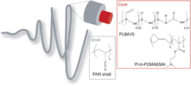
Here, we show first, encouraging results on the nanomanufacturing of electrospun block copolymer/polymer derived ceramic (PDC) precursor nanocomposite fibers with complex and ordered confinement-induced fiber morphologies, circumventing the aforementioned limitations. Coaxial electrospinning30,31 was used to produce core-shell fibers in which the nanocomposites were enveloped in a rigid polyacrylonitrile (PAN) shell (see Scheme 1). We show that in this way (i) we avoid the kinetic limitations of sol–gel approaches, and (ii) long-range order can be induced by a post-synthesis annealing step that is independent from polymerization/crosslinking of the PDC resin. For a block copolymer/PDC precursor nanocomposite that formed a two-dimensional hexagonal morphology in the bulk, structural analysis by transmission electron microscopy (TEM) suggested nanofibers with helical and stacked toroidal mesostructures. To the best of our knowledge, this is the first time that block copolymer/inorganic precursor nanocomposites with these confinement-induced morphologies are obtained through a continuous and very practical nanofiber formation route. Removal of the organics and functionalization of the resulting nanocomposite fibers may lead to multifunctional, porous ceramic materials.
 | ||
| Scheme 1 A schematic representation of the core-shell fiber polymer chemistry. The fiber consists of a PI-b-PDMAEMA/PUMVS nanocomposite core and a PAN shell. The PUMVS molecule has cyclic and linear features; R = H or vinyl, no information is available on R′. | ||
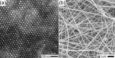
The precursor solution for the core consisted of an amphiphilic block copolymer, a PDC precursor for SiCN type materials, a radical initiator and a solvent. The block copolymer poly(isoprene-block-dimethylaminoethyl methacrylate) (PI-b-PDMAEMA) was used as a structure directing agent for the PDC precursor, poly(ureamethylvinyl)silazane (PUMVS). Mixing the block copolymer with PUMVS is expected to lead to preferential swelling of the PDMAEMA domains with PUMVS due to its polar nature. Earlier, we showed that, for bulk materials, well-defined mesophases (2D hexagonal, lamellar and spherical) can be obtained by systematically increasing the PUMVS to block copolymer volume fraction, providing a one-pot type approach towards mesoporous high temperature ceramics.32–34 Hexane was selected as a solvent, because it ensures solubility of all components (the block copolymer, PUMVS and radical initiator), even at high concentrations, and is immiscible with the solvent used for the shell, dimethylformadide (DMF). High solubility of all components is necessary, because the core solution must possess a certain minimum viscosity to prevent jet breakup of the core.35 If the core and shell solvents are miscible, mixing might occur between the two phases, making it difficult to achieve well-defined core-shell structures.36Fig. 1a shows a transmission electron microscopy (TEM) image of a section microtomed from a thick film cast from such a core solution at 50 °C with subsequent annealing at 50 °C for 24 h and crosslinking at 130 °C for 3 h. The contrast in this image arises from the electron density difference between PI and PDMAEMA/PUMVS domains, the latter appearing darker. The TEM image clearly suggests a 2D hexagonal cylinder structure, consistent with earlier results for this composition.37 Small angle X-ray scattering corroborated this structural interpretation, providing a center-to-center distance, L0, between cylinders in the bulk of 33.0 nm (see Fig. S6 in the ESI†).
 | ||
| Fig. 1 (a) A TEM image of bulk composite showing hexagonally packed cylinders. (b) A SEM image of annealed core-shell electrospun fibers. | ||
The shell solution in the electrospinning experiments was an 8 wt% PAN solution in DMF. The concentration of the shell solution was chosen such that is was suitable for electrospinning by itself, which is desirable because the core solution is not electrospinnable by itself.38 Lower concentrations can lead to bead formation, whereas higher concentrations lead to thicker fibers (see Fig. S1–S3 in ESI†). The primary function of the PAN shell was to confer mechanical stability to the fiber core. Both blocks of PI-b-PDMAEMA and PUMVS have low Tg's (Tg, PI = −60 °C, Tg, PDMAEMA = 25 °C, Tg, PUMVS ≪ 25 °C).39–41 Electrospinning of this mixture without a shell would thus result in immediate loss of fiber integrity. Additionally, the PAN shell serves as a mechanism for tuning fiber diameter, producing ultrathin core diameters by varying the core/shell flow rate ratio. The melting temperature of the PAN (Tm,PAN = 317 °C)42 outer shell is also high enough to allow annealing of the composite and crosslinking of the PUMVS without losing the integrity of the fiber.43–45 A polymer was selected over an inorganic sol–gel derived shell material also because PUMVS reacts with alcohols and water. Using a (hydrolytic) sol–gel would lead to crosslinking and subsequent precipitation of the PUMVS when the solutions meet at the tip of the capillary, making electrospinning challenging.
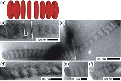
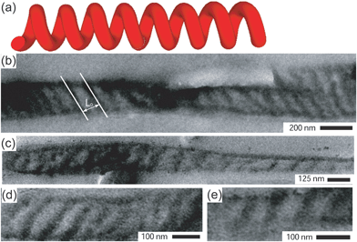
Coaxial fibers were spun at room temperature at an electrical potential of 20 kV. Fig. 1b shows a typical scanning electron micrograph (SEM) of crosslinked core-shell fibers with a diameter in the range of 100–300 nm. In Fig. 2 and 3, TEM images are shown of fibers cut parallel to the fiber axis (see Fig. S4 and S5 in the ESI for fibers cut perpendicular to the fiber axis†). The confinement directed the self-assembly process to form well-developed morphologies different from the 2D hexagonal structure observed in the bulk. Fig. 2 shows fibers with core diameters (Dc) in the range of 100–155 nm with alternating light (PI) and dark (PDMAEMA/PUMVS) domains that are oriented more or less perpendicular to the fiber axis, suggesting a stacked disk or toroid morphology. Core diameters determined from TEM images might underestimate the true diameter, because slices made by microtoming may not always go through the fiber center. The domains of fibers depicted in Fig. 3 are at a constant angle to the fiber axis, suggesting a helical or tilted disk morphology with a Dc of 65–185 nm.
 | ||
| Fig. 2 (a) A schematic representation of a stacked toroid morphology. (b)–(f) TEM images of fibers cut parallel to the fiber axis consistent with a stacked toroid morphology. The image in (b) shows how the characteristic structural repeat distance, L0, was determined. | ||
 | ||
| Fig. 3 (a) A schematic representation of a helical morphology. (b)–(e) TEM images of fibers cut parallel to the fiber axis consistent with a helical morphology. The image in (b) shows how the characteristic structural repeat distance, L0, was determined. | ||
The characteristic repeat distances of the domains in these fibers were determined from TEM micrographs as indicated in Fig. 2b and 3b, and varied between 29–54 nm. This range envelops the repeat distance of cylinders in the bulk, L0 (L0 = 33.0 nm). The variation might be due to (residual) confinement frustrations.46 Furthermore, the core diameter can vary along a single fiber. The similarity between the repeat distance and L0 is rationalized by regarding the cylindrical confinement as a coiled-up flat surface, as proposed by Wu et al.,10 indicating that the mechanism of the formation of these structures is a consequence of relieving the imposed structural frustrations. Rolling up parallel cylinders leads to the construction of stacked toroids and helices depending on the rolling scheme.
Stacked toroids or helices were theoretically predicted in recent Monte Carlo simulations.47,48 The morphological behavior of cylinder forming block copolymers was studied under cylindrical confinement as a function of the ratio Dc/L0 and block copolymer/wall interaction strength. In the present system, the PAN wall probably weakly attracts the majority phase (PDMAEMA + PUMVS), because the χ parameters (χPI-PAN ≈ 0.358 and χPI-PDMAEMA ≈ 0.309)39 suggest that the hydrophilic PDMAEMA would have preferred interactions with the PAN shell. In our studies the electrospun fibers had Dc/L0 ratios in the range of 2.5–5. For these values, ring structures, including stacked (tilted) toroids, as well as single and double helices were predicted. This is consistent with our TEM results. Schematic representations of these structures can be found in Fig. 2a and 3a. While stacked disks were also both predicted47,48 and experimentally observed,22 the corresponding Dc/L0 ratios were much lower than in our experimental work. We therefore conclude that the morphologies observed in our TEM experiments are most likely stacked toroids rather than stacked disks. For Dc/L0 ratios larger than ∼4 the predicted structures exhibited several layers in the radial direction, which we did not observe in our experiments. Differences between experiment and theory may arise as the simulations are based on pure block copolymer systems, whereas the present nanocomposite system is closer to a diblock copolymer/homopolymer mixture. It should be noted that based on our simple TEM analysis we cannot exclude the possibility that the observed morphologies are (non-equilibrium) tilted toroid or disk morphologies rather than the expected helical morphology. From previous experience with this system in the bulk, however, we know that the fibers are annealed long enough to approach thermal equilibrium suggesting that the system is not far from equilibrium.
It is interesting to note that the two observed morphologies are formed in the same core diameter range, consistent with earlier results obtained for nanorods.10 This observation indicates that these morphologies must have similar energies. This hypothesis is again consistent with Monte Carlo simulation results, where degenerate structures (single helices, stacked toroids and double helices) are found for certain Dc/L0 ratios.
We have demonstrated a versatile approach towards the nanomanufacturing of continuous nanocomposite fibers with ordered morphologies, which may lead to the production of highly functional and porous fibers. The focus of future work will be to convert these composites to ceramic nanostructures. This is a challenge because of the volume change of PAN during pyrolysis, causing internal stresses and easily leading to a collapse of the nanostructures. The observed nanostructured fibers may have potential towards applications in areas like catalysis, sensing, and separation. The possible chirality of the helical structures could be particularly interesting for applications like enantioselective separation.
Acknowledgements
The authors thank Jeanne Panels and Vibha Kalra for help with electrospinning experiments. The financial support of the National Science Foundation (award DMR-0605856) is gratefully acknowledged. The work was further supported by the Cornell Center for Materials Research (CCMR), a Materials Research Science and Engineering Center of the National Science Foundation (DMR-0520404) and by the U.S. Department of Homeland Security under Cooperative Agreement Number “2009-ST-108-LR0006”.References
- M. Templin, A. Franck, A. DuChesne, H. Leist, Y. M. Zhang, R. Ulrich, V. Schadler and U. Wiesner, Science, 1997, 278, 1795–1798 CrossRef CAS.
- M. A. Hillmyer, P. M. Lipic, D. A. Hajduk, K. Almdal and F. S. Bates, J. Am. Chem. Soc., 1997, 119, 2749–2750 CrossRef CAS.
- D. Y. Zhao, J. L. Feng, Q. S. Huo, N. Melosh, G. H. Fredrickson, B. F. Chmelka and G. D. Stucky, Science, 1998, 279, 548–552 CrossRef CAS.
- Y. Wan and D. Y. Zhao, Chem. Rev., 2007, 107, 2821–2860 CrossRef CAS.
- S. C. Warren, L. C. Messina, L. S. Slaugther, M. Kamperman, Q. Zhou, S. M. Gruner, F. DiSalvo and U. Wiesner, Science, 2008, 320, 1748–1752 CrossRef CAS.
- G. E. S. Toombes, S. Mahajan, M. Thomas, P. Du, M. W. Tate, S. M. Gruner and U. Wiesner, Chem. Mater., 2008, 20, 3278–3287 CrossRef CAS.
- G. E. S. Toombes, S. Mahajan, M. Weyland, A. Jain, P. Du, M. Kamperman, S. M. Gruner, D. A. Muller and U. Wiesner, Macromolecules, 2008, 41, 852–859 CrossRef CAS.
- B. K. Cho, A. Jain, S. Mahajan, H. Ow, S. M. Gruner and U. Wiesner, J. Am. Chem. Soc., 2004, 126, 4070–4071 CrossRef CAS.
- B. K. Cho, A. Jain, S. M. Gruner and U. Wiesner, Science, 2004, 305, 1598–1601 CrossRef CAS.
- Y. Y. Wu, G. S. Cheng, K. Katsov, S. W. Sides, J. F. Wang, J. Tang, G. H. Fredrickson, M. Moskovits and G. D. Stucky, Nat. Mater., 2004, 3, 816–822 CrossRef CAS.
- Y. Wang, Y. Qin, A. Berger, E. Yau, H. Changcheng, L. Zhang, U. Goesele, M. Knez and M. Steinhart, Adv. Mater., 2009, 21, 2763–2766 CrossRef CAS.
- Y. Dzenis, Science, 2004, 304, 1917–1919 CrossRef CAS.
- D. H. Reneker and I. Chun, Nanotechnology, 1996, 7, 216–223 CrossRef CAS.
- D. Li and Y. N. Xia, Adv. Mater., 2004, 16, 1151–1170 CrossRef CAS.
- A. Greiner and J. H. Wendorff, Angew. Chem., Int. Ed., 2007, 46, 5670–5703 CrossRef CAS.
- H. Fong and D. H. Reneker, J. Polym. Sci., Part B: Polym. Phys., 1999, 37, 3488–3493 CrossRef CAS.
- M. L. Ma, R. M. Hill, J. L. Lowery, S. V. Fridrikh and G. C. Rutledge, Langmuir, 2005, 21, 5549–5554 CrossRef CAS.
- T. Ruotsalainen, J. Turku, P. Heikkila, J. Ruokolainen, A. Nykanen, T. Laitinen, M. Torkkeli, R. Serimaa, G. ten Brinke, A. Harlin and O. Ikkala, Adv. Mater., 2005, 17, 1048–1052 CrossRef CAS.
- V. Kalra, P. A. Kakad, S. Mendez, T. Ivannikov, M. Kamperman and Y. L. Joo, Macromolecules, 2006, 39, 5453–5457 CrossRef CAS.
- T. Ruotsalainen, J. Turku, P. Hiekkataipale, U. Vainio, R. Serimaa, G. ten Brinke, A. Harlin, J. Ruokolainen and O. Ikkala, Soft Matter, 2007, 3, 978–985 RSC.
- Y. Wang, Y. Qin, A. Berger, E. Yau, C. C. He, L. B. Zhang, U. Gosele, M. Knez and M. Steinhart, Adv. Mater., 2009, 21, 2763–2766 CrossRef CAS.
- P. Dobriyal, H. Q. Xiang, M. Kazuyuki, J. T. Chen, H. Jinnai and T. P. Russell, Macromolecules, 2009, 42, 9082–9088 CrossRef CAS.
- R. Kessick and G. Tepper, Appl. Phys. Lett., 2004, 84, 4807–4809 CrossRef CAS.
- S. Chen, H. Hou, P. Hu, J. H. Wendorff, A. Greiner and S. Agarwal, Macromol. Mater. Eng., 2009, 294, 265–271 CrossRef CAS.
- S. H. Zhan, D. R. Chen, X. L. Jiao and Y. Song, Chem. Commun., 2007, 2043–2045 RSC.
- C. Daniel, I. W. Hamley and K. Mortensen, Polymer, 2000, 41, 9239–9247 CrossRef CAS.
- R. Seguela and J. Prudhomme, Macromolecules, 1981, 14, 197–202 CrossRef CAS.
- T. Pakula, K. Saijo, H. Kawai and T. Hashimoto, Macromolecules, 1985, 18, 1294–1302 CrossRef CAS.
- G. Kim and M. Libera, Macromolecules, 1998, 31, 2569–2577 CrossRef CAS.
- I. G. Loscertales, A. Barrero, I. Guerrero, R. Cortijo, M. Marquez and A. M. Ganan-Calvo, Science, 2002, 295, 1695–1698 CrossRef CAS.
- A. K. Moghe and B. S. Gupta, Polym. Rev., 2008, 48, 353–377 Search PubMed.
- M. Kamperman, C. B. W. Garcia, P. Du, H. S. Ow and U. Wiesner, J. Am. Chem. Soc., 2004, 126, 14708–14709 CrossRef CAS.
- M. Kamperman, M. A. Fierke, C. B. W. Garcia and U. Wiesner, Macromolecules, 2008, 41, 8745–8752 CrossRef CAS.
- M. Kamperman, A. Burns, R. Weissgraeber, N. van Vegten, S. C. Warren, S. M. Gruner, A. Baiker and U. Wiesner, Nano Lett., 2009, 9, 2756–2762 CrossRef CAS.
- D. Li and Y. Xia, Nano Lett., 2004, 4, 933–938 CrossRef CAS.
- D. Li, J. T. McCann and Y. Xia, J. Am. Ceram. Soc., 2006, 89, 1861–1869 CrossRef CAS.
- M. Kamperman, P. Du, R. O. Scarlat, E. Herz, U. Werner-Zwanziger, R. Graf, J. W. Zwanziger, H. W. Spiess and U. Wiesner, Macromol. Chem. Phys., 2007, 208, 2096–2108 CrossRef CAS.
- J. H. Yu, S. V. Fridrikh and G. C. Rutledge, Adv. Mater., 2004, 16, 1562–1566 CrossRef CAS.
- Polymer Handbook, ed. J. Brandup, E. H. Immergut and E. A. GrulkeWiley, New York, 1999 Search PubMed.
- S. Renker, Doctoral dissertation, Max Planck Institute for Polymer Research, Mainz, Germany, 2003.
- CERASET SN Inorganic Polymer Technical Bulletin, Lanxide Co., 1997 Search PubMed.
- http://www.sigmaaldrich.com/catalog/search/ProductDetail/ALDRICH/181315 .
- V. Kalra, S. Mendez, J. H. Lee, H. Nguyen, M. Marquez and Y. L. Joo, Adv. Mater., 2006, 18, 3299–3303 CrossRef CAS.
- M. L. Ma, V. Krikorian, J. H. Yu, E. L. Thomas and G. C. Rutledge, Nano Lett., 2006, 6, 2969–2972 CrossRef CAS.
- V. Kalra, J. Lee, J. H. Lee, S. G. Lee, M. Marquez, U. Wiesner and Y. L. Joo, Small, 2008, 4, 2067–2073 CrossRef CAS.
- M. L. Ma, K. Titievsky, E. L. Thomas and G. C. Rutledge, Nano Lett., 2009, 9, 1678–1683 CrossRef CAS.
- B. Yu, P. C. Sun, T. C. Chen, Q. H. Jin, D. T. Ding, B. H. Li and A. C. Shi, Phys. Rev. Lett., 2006, 96, 138306 CrossRef.
- B. Yu, Q. H. Jin, D. T. Ding, B. H. Li and A. C. Shi, Macromolecules, 2008, 41, 4042–4054 CrossRef CAS.
Footnotes |
| † Electronic supplementary information (ESI) available: Experimental methods. See DOI: 10.1039/c0py00146e |
| ‡ Present address: Leibniz Institute for New Materials, Campus D2 2, 66123 Saarbrücken, Germany. |
| § Present address: Macromolecular Science and Engineering, Case Western Reserve University, 2100 Adelbert Road, Kent Hale Smith Building, RM 522, Cleveland, OH 44106-7202, USA. |
| This journal is © The Royal Society of Chemistry 2010 |
