Recent developments in polymer stabilised liquid crystals
Ingo
Dierking
*
School of Physics and Astronomy, University of Manchester, Oxford Road, Manchester, M13 9PL, UK. E-mail: ingo.dierking@manchester.ac.uk
First published on 1st June 2010
Abstract
Polymer stabilised liquid crystals describe systems in which a polymer network is formed within an anisotropic liquid crystal matrix. During the polymerisation process a bi-continuous system is formed, where a continuous polymer network permeates a continuous liquid crystal phase. The order and structure of the liquid crystal phase are transferred onto the polymer network, which thus mechanically stabilises the phase it was formed in. Such systems have attracted increasing interest over the last 15 years, as they are serious candidates in the development of electronic paper, but also for the mechanical stabilisation of smectic ferroelectric liquid crystals, which exhibit some very superior electro-optic properties over their nematic counterparts found in most common LCDs today. In the last few years some remarkable developments in the field of polymer stabilised liquid crystals took place, some of more academic interest, but others certainly also of interest for future display and optical component applications. Some examples of both will be discussed.
 Ingo Dierking | Dr Dierking received his PhD in 1995 and after a period at IBMs T. J. Watson Research Center in the USA, he became a Feodor-Lynen fellow of the Humboldt society at Chalmers University in Sweden, where he was also appointed as docent (assistant professor). He then spent three years at Darmstadt University in Germany, before being appointed at the University of Manchester. Dr Dierking is currently a Senior Lecturer (associate professor) at the School of Physics and Astronomy. His main areas of research are polymer stabilised liquid crystals, LC-nanoparticle dispersions, defect formation and annihilation, and chiral liquid crystals. |
1. Introduction
Liquid crystals1–3 are anisotropic fluids, which exhibit spontaneous orientational order of (often) rod-like molecules, called the nematic phase, and in addition sometimes low dimensional positional order, called the fluid smectic phases (smectic A and smectic C). A schematic introductory view is given in Fig. 1, but it should be stressed that this representation only scratches the surface, as there are about 30 different thermodynamically distinct liquid crystalline phases known today.4 These can also be constituted of shape-anisotropic molecules of non-rod-like nature, such as disks5 or bent-core molecules.6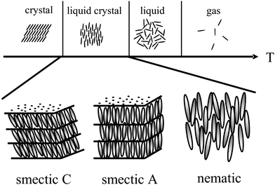 | ||
| Fig. 1 Schematic illustration of the occurrence of thermotropic liquid crystal phases as an intermediate state between the solid crystal and the isotropic liquid. Liquid crystals exhibit both, anisotropy of physical properties, alongside with flow properties of a viscous liquid. A large variety of liquid crystal phases are distinguished, the most prominent being shown; the nematic phase with only orientational order of the long axis of elongated molecules, and the fluid smectic phases (smectic A and smectic C) which exhibit additional one-dimensional positional order. | ||
Of special interest in the study of liquid crystals over the last three decades has been the fact that liquid crystalline materials can easily be made chiral, i.e. introducing a molecular lack of mirror symmetry which will be reflected in the structure and properties of the liquid crystal phase.7 This can be done by making the liquid crystal molecules themselves chiral, by adding chiral dopants, or a combination of both, the latter method allowing for an easier way to tune chiral properties over large parameter spaces. Addition of chirality to liquid crystals results in (i) the formation of helical superstructures, such as the chiral nematic or cholesteric phase,8,9 (ii) the occurrence of novel frustrated phases, such as the Blue Phases (BP)10,11 and the Twist Grain Boundary (TGB) Phases,12,13 and (iii) the observation of novel physical phenomena, such as selective reflection14,15 and ferroelectricity in fluid media.16–18 The relevant structures and properties will be introduced below, together with the discussion of experimental results.
Polymer stabilised liquid crystals (PSLCs)19,20 are generally formed by dispersing a small amount (<10% by weight) of a photo-reactive, shape-anisotropic, bi-functional molecule (often liquid crystalline by itself) into a liquid crystal matrix, and subsequent photo-polymerisation through irradiation with UV light. The general idea behind PSLCs is that the spontaneous liquid crystalline order, i.e. the structure of self-organised systems, is transferred onto the dispersed, polymerisable molecules, and once oriented in the desired configuration, polymerisation is initiated. The resulting polymer network will then template the self-organised order of the liquid crystal phase it was formed in, and thus stabilises its structure and properties.
This was first demonstrated for a simple nematic liquid crystal under varying boundary conditions,21,22 but chiral systems like cholesterics23,24 and ferroelectric25 and antiferroelectric liquid crystals26 soon followed to be investigated, because of their more promising applicational prospects. Nevertheless, researchers encountered huge problems in the description of polymer stabilised liquid crystals, because these systems are extremely complex. The properties of electro-optic devices are profoundly influenced by the morphology of the formed polymer network. This is mainly governed by the Flory–Huggins theory of polymer solubility; poorly soluble monomers generally result in polymer networks with little orientational order, similar to networks formed in the isotropic phase, while well soluble monomers form networks which closely template the liquid crystalline order they are formed in.27 The anisotropic network morphology in turn is largely dominated by the processing conditions, such as monomer content and solubility,27–29 temperature of polymerisation,30 UV intensity and dose,31etc., a variable parameter space which probably may only be understood on a qualitative level, providing rules of thumb at the best. Fractal geometric methods may lead to certain descriptions of the polymer network influence in relation to network morphology,32 and scaling laws in relation to electro-optic properties,33,34 but considerably more work is needed to arrive at a quantitative understanding of the general interactions between polymer network and liquid crystal. For current applications systems are employed where the polymer networks reflect the anisotropy of the liquid crystal they were formed in. Isotropic polymer networks are of some fundamental interest in relation to studies of liquid crystals in confined geometries.
However, in the last few years, considerable understanding has been gained in the field of polymer stabilised liquid crystals. This includes the methodical use of these systems in defect and structure visualisation, the first quantitative determinations of the interactions between polymer networks dispersed within a ferroelectric liquid crystal, and several innovative concepts for the application of PSLCs for novel and improved devices. Some of these academic as well as applicational innovations will be reviewed below.
2. Defect and structure imaging
Like all condensed matter systems, liquid crystals exhibit a wealth of topological defects,35 point defects, line defects, loops, disclinations and dislocations. Being a member of the “soft matter family”, i.e. materials with extremely small elastic constants in comparison to solid state matter, liquid crystal defects extend not over distances of several atoms as in solid state physics, but rather tens of micrometres.36 This, together with the property of birefringence, makes it comparably easy to study defects in liquid crystals simply by polarising optical microscopy (POM) and digital image acquisition.The disadvantage is that equivalent POM images can result from different director fields. For example, an s = +1 point defect in a planar orientated nematic Schlieren texture cannot be distinguished from its s = −1 counterpart, unless the sample is actively rotated between crossed polarisers. But still this does not allow an identification of the actual director field, nor does it present a method to distinguish between different topological defects of the same strength and the same sign, which may also exist simultaneously in a single sample.37 It appears that only few experimental attempts have been made to actually visually image the director field of a liquid crystal, and especially its orientational structure in the vicinity of defects. One such successful attempt was achieved via the decoration of a liquid crystal with micrometre sized particles.38
The method of “polymer stabilisation” provides a relatively simple tool to image liquid crystal director fields in two dimensional space. Since the polymer network templates the macroscopic structure of the liquid crystal that it was formed in, the director fields of defect structures can be visualised by polymerizing respective monomers into a network, washing out the liquid crystal with a suitable solvent, and imaging the remaining polymer network by scanning electron microscopy (SEM). An illustrative example is given in Fig. 2(a), which displays the polymer network formed in a nematic Schlieren texture, exhibiting the director field in the vicinity of a pair of s = +1 and s = −1 point defects,39 together with the long proposed schematic director fields of the individual defects (Fig. 2(b)). From Fig. 2 it is obvious that prediction and experiment coincide, with the polymer network neatly following the director configurations proposed for both defect types, s = +1 and s = −1. Also the director configurations of other defects can be visualised, like ±1/2 Schlieren defects, but also the much more rare s = +1 vortex and swirl defects,39 which cannot be distinguished optically from the Schlieren defects.
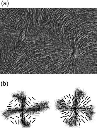 | ||
| Fig. 2 Defect imaging of a pair of s = +1 (right) and s = −1 (left part of the image) nematic Schlieren defects. (a) SEM image of the polymer network following the liquid crystal director configuration in which it was formed. (b) Schematic illustration of the director field suggested by polarizing microscopic investigations. | ||
It is worthwhile to mention that this method of director field imaging can also be applied to other, three dimensional systems. The helical structure of the chiral nematic or cholesteric phase was demonstrated through so-called Bouligand cuts, oblique cuts through a helical superstructure, and SEM imaging of the expected arc structure.28 Also the discontinuous twisted structure of twist grain boundary (TGB) phases could be demonstrated recently.40
3. Polymer stabilised ferroelectric liquid crystals
Ferroelectric liquid crystals (FLC)16–18 promise much improved performance in display and optic devices, because their response time is about a factor of 1000 faster than that of conventional nematic liquid crystals. At the same time, the switching process practically takes place in the plane of the substrate, thus intrinsically providing better viewing angles. Nevertheless, there are unfortunately also drawbacks, like the formation of zigzag defects during the SmA* to SmC* transition, the formation of chevron structures, and the poor mechanical stability towards pressure and deformations of the smectic layer structure. Polymer stabilisation is one way to improve performance41 and mechanically stabilise director structures.For this, it is of great importance to fundamentally understand the elastic interactions between the ferroelectric liquid crystal and the dispersed polymer network. First attempts towards such an understanding were already made a decade ago,42 based on measurements of the spontaneous polarisation through the paraelectric to ferroelectric SmA*–SmC* transition. It was then found that the influence of the polymer network increases linearly with polymer network concentration. Similar results were more recently obtained through investigations of the SmA* phase43 and the short pitch SmC* phase,44 while a rigorous experimental and theoretical treatment was still outstanding. This was recently established through the development of a modified general Landau theory for polymer stabilised ferroelectric liquid crystals.45,46 The elastic coupling between a FLC and a polymer network was determined on a quantitative basis, and related to theory. Fig. 3 illustrates the different contributions to the Landau potential:
 | (1) |
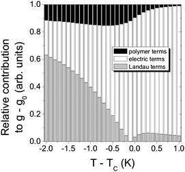 | ||
| Fig. 3 Quantitative determination of the influence of a polymer network on a ferroelectric liquid crystal host (black). Also shown is the contribution of the Landau terms (thermodynamics, gray), and the electric terms (polarization coupling and applied electric field, white). The dispersed polymer network accounts for up to 15% of the total interaction energy. (Reproduced by permission from ref. 45.) | ||
4. Polymer stabilised Blue Phases
As pointed out above, the introduction of chirality into liquid crystals can not only lead to novel effects and structures, but even to novel phases, generally called frustrated phases, as they result from the competition between chirality (helicity) and thermodynamics (the formation of ordered structures). One such example is the so-called Blue Phases (BP),10,11 phases with a cubic lattice of defects formed at the points where three double twist cylinders intersect. Kikuchi and co-workers48,49 have very elegantly visualised the structure of the BPI by confocal laser scanning microscopy on polymer stabilised samples. Their images are shown in Fig. 4, depicting several different lattice planes, with “a” being the dimension of the unit cell, which is in the order of a few hundred nm, and in agreement with expectations from selective reflection measurements. The demonstrated structure is of the body centred cubic type (bcc).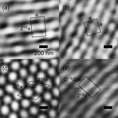 | ||
| Fig. 4 Confocal laser scanning images of the polymer stabilized liquid crystalline Blue Phase I, which exhibits a body centered cubic structure of defects. (a) {110} plane, (b) {100} plane, (c) {111} plane, and (d) {211} plane. The images verify the structure of the BPI phase. (Reproduced by permission from ref. 49.) | ||
Due to their generally only very small temperature range of existence, often less than a degree, the Blue Phases have long been thought to be of purely academic interest. Only very recently have prototype displays based on Blue Phases been demonstrated.50 Also their use in the formation of tunable photonic materials and fast optical modulators is now being discussed. There are several advantages of using Blue Phases in optical devices: the lack of a need for alignment, submillisecond response times, and large viewing angles.51 However, the small temperature range has long presented a problem. It was again Kikuchi and co-workers,52,53 who proposed the use of polymer stabilisation to increase the existence range of Blue Phases to values acceptable for applicational use. While most polymer stabilised samples showed an increase in phase stability by approximately a factor of five, some samples exhibited a remarkable Blue Phase existence range of more than 60 K. These were exclusively samples with a relative large amount of monomer, >6 mol%. It is believed that the polymer network forms in the disclination lattice of the Blue Phase, thus lowering the contribution of elastic energy through defects, and therefore increasing the phase stability of BPI. The authors also demonstrated electro-optic response times, rise as well as decay times, at sub-microsecond speeds at room temperature.
5. Polymer stabilised cholesterics beyond the reflectance limit
Due to their helical superstructure, cholesteric liquid crystals selectively reflect circular polarised light of a handedness that does not match that of the twist. (Using the definition of left- and right-circular polarised light by Max Born, viewing in the direction of the light source, i.e. antiparallel to the direction of light propagation, a right handed cholesteric helix reflects right circular polarized (rcp) light, which describes a left handed helix in space.) The handedness that does match the twist of the helix is transmitted. It thus appears that one can only hope for a maximum reflection of 50% of the incoming light. The wavelength λ0 of the reflected light for normal incidence, i.e. light propagation along the helix axis, is closely related to the pitch P of the helical superstructure viaλ0 = 〈n〉P, where 〈n〉 is the average refractive index. P is generally a function of temperature with 1/P ≈ T and blue light being reflected at higher and red light at lower temperatures. Thus, if the pitch is of the order of the wavelength of visible light, this selective reflection leads to the striking colour play exhibited by heat sensitive foils or the fashionable mood rings (where special mixtures are used such that blue represents cold and red represents warm). But also outside the visible spectrum, for example in the IR range, cholesteric liquid crystals reflect light, which can be of interest for heat repelling windows or paints.It is thus desirable to develop a simple method with a single liquid crystal layer that goes beyond the theoretical reflectance limit of a standard cholesteric liquid crystal layer. Mitov and Dessaud have done just that.54,55 By using a rather special cholesteric liquid crystal host, a so-called twist inversion compound, a material which not only changes the pitch but also the handedness of its helical superstructure as a function of temperature, they proposed a device based on polymer stabilisation, which reflects IR radiation in excess of 50%. The construction was relatively simple: a polymer network was formed within the cholesteric host at a certain pitch and handedness. As pointed out above, this network forms a continuous, phase separated structure in the continuous liquid crystal phase, templating its self-organisation. Then, the temperature is changed, crossing the twist inversion temperature, and thus changing the handedness of the liquid crystal helix, while that of the polymer network is spatially preserved. If the temperature is changed so far as to produce a cholesteric of the same pitch, but of opposite handedness, light is reflected beyond the reflectance limit. This is demonstrated in Fig. 5. The physical reason is that in the vicinity of the polymer network strands elastic interactions between the cholesteric liquid crystal and the polymer locally force the liquid crystal into the opposite handedness. This is much like the above discussed effect of having a network being formed in the SmA* phase reducing the average tilt angle in the SmC* phase.
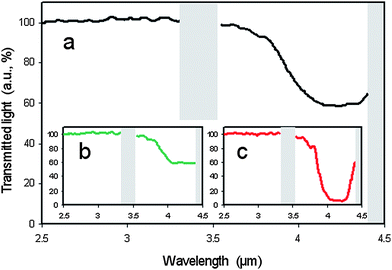 | ||
| Fig. 5 Experimental demonstration of polymer stabilized cholesteric reflectivity beyond the theoretical limit. Looking at a wavelength of approximately λ = 4 µm (a) about 50% of the light is reflected before polymerization is initiated. (b) Also 50% of the light is reflected when a right handed polymer network is formed in the right handed cholesteric phase, still as expected from standard theory. (c) When the twist inversion liquid crystal is taken to temperatures where its twist sense is inverted, a left handed cholesteric phase is hosting a right handed polymer network structure. Due to elastic interactions between the liquid crystal and the polymer network, the hybrid material reflects light of both handedness, resulting in a reflectivity of about 95%. (Reproduced by permission from ref. 54.) | ||
Guo et al.56 have followed a similar idea, which may be a bit more time consuming with respect to sample preparation, but is more flexible with respect to working temperatures, including room temperature materials. They use what they call the wash-out/refill method. A polymer network of a certain pitch and handedness is formed within a tailored liquid crystal mixture. After polymerisation the original liquid crystal is removed by a suitable solvent, and subsequently replaced by a cholesteric mixture of the opposite handedness. The physical reason of observing close to 100% reflection at a certain wavelength band is the same as outlined above. And it appears that these systems are relatively easily adjustable to application requirements, although I do see disadvantages in actual production processes, because the original liquid crystal needs to be physically removed.
6. Innovative applications of polymer stabilised liquid crystals
Adding polymer stabilisation to existing display technologies can enhance electro-optic performance, although at the cost of an additional production step, the actual polymerisation process itself. Especially, switching speeds and director field stability may be improved, as for example outlined above for ferroelectric liquid crystals (FLC). But also nematic display modes can be improved, notably in dynamic response. Huang et al.57–59 have demonstrated sub-microsecond switching in dual-frequency polymer stabilised π cells with good dark state and low operating voltages.Haseba et al.60 and Choi et al.61,62 are employing the polymer stabilised isotropic phase of a liquid crystal together with the Kerr effect, a quadratic change in refractive index with applied electric field amplitude, to achieve optically isotropic-nanostructured liquid crystalline phases with fast electro-optic response times. The device uses interdigitated in-plane electrodes, and is schematically demonstrated in Fig. 6. In the zero field state, the device remains isotropic and thus appears black between crossed polarizers. Application of an electric field results in a coherently induced birefringence via the Kerr effect in microscopic domains. When the field is turned off, polymer stabilisation quickly returns the liquid crystal into a microscopically isotropic arrangement. Features are a sub-microsecond dynamic response, greyscale capability, high contrast ratio, and no need for alignment layers.
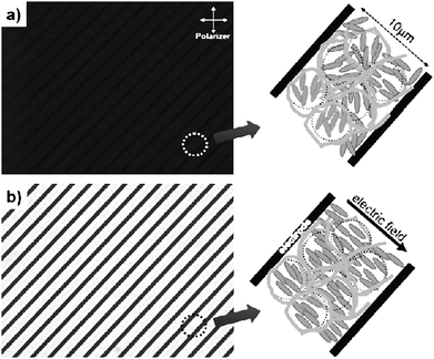 | ||
| Fig. 6 Optical textures of (a) a polymer stabilized isotropic phase, and (b) the oriented state due to the Kerr effect. The left hand part of the figures shows the experimental realization, employing an interdigitated electrode structure, while the right hand side provides a schematic illustration of the effect. (Reproduced by permission from ref. 62.) | ||
At last, Yang and co-workers63 have revisited the decade old idea of switching between a transparent and a scattering state in devices which do not rely on polarisers. But this time not with a view on display applications such as electronic paper, revealing information through application of electric fields, but rather through change of temperature. They use the transition between the homeotropically oriented low temperature non-scattering, and thus transmitting SmA* state, and the high temperature scattering, and thus reflecting cholesteric (N*) state, with small focal conic domains. The sample is polymer stabilised in the homeotropic SmA* state. Hysteresis effects at the SmA*–N* transition seem to be practically negligible and the process is reproducible over many cycles of temperature variation. It is clear that this concept could make a good candidate for temperature controlled window blinds. Its principle and performance are demonstrated in Fig. 7.
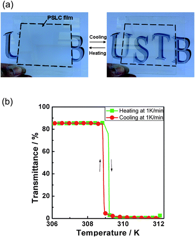 | ||
| Fig. 7 Demonstration of a temperature steered on–off switch, which employs a scattering–non-scattering transition between the cholesteric and the smectic A phase. The system is polymer stabilised in the transmissive homeotropic orientation of the SmA phase, and on increasing temperature the light scattering focal conic orientation of the cholesteric phase is adopted. Polymer stabilization makes this transition reversible. (a) Device demonstration and (b) quantitative experimental results. (Reproduced by permission from ref. 63.) | ||
7. Conclusions
Polymer stabilisation has been an interesting and innovative topic in liquid crystal research since its first demonstration in 1992. It has since penetrated a variety of fields in liquid crystal research, from fundamental questions and basic research, mainly centred around the interactions in such bi-continuous systems, to very applied issues in liquid crystal displays, ferroelectric liquid crystals, vertically aligned nematics, electronic paper, and also non-display applications such as sensors or simply heat repellent sheets. This “mini-review” tried to address the most exciting areas of polymer stabilised liquid crystals over the last few years, but naturally from a personal point of view. Surely, some other interesting developments were omitted. Nevertheless, I hope that I could convince a broad audience, hopefully much broader than the liquid crystal community itself, that polymer stabilised liquid crystals are a fascinating class of functional materials, which offer great prospect for future applications. At the same time, let us not forget that future applications are most generally built on firstly developing a fundamental understanding.References
- P. J. Collings and M. Hird, Introduction to Liquid Crystals: Chemistry and Physics, Taylor & Francis, London, 1997 Search PubMed.
- S. Chandrasekhar, Liquid Crystals, Cambridge University Press, Cambridge, 2nd edn, 1992 Search PubMed.
- P. G. deGennes and J. Prost, The Physics of Liquid Crystals, Clarendon Press, Oxford, 2nd edn, 1993 Search PubMed.
- I. Dierking, Textures of Liquid Crystals, Wiley-VCH, Weinheim, 2003 Search PubMed.
- S. Chandrasekhar and G. S. Ranganath, Rep. Prog. Phys., 1990, 53, 57 CrossRef CAS.
- G. Pelzl, S. Diele and W. Weissflog, Adv. Mater., 1999, 11, 707 CrossRef CAS; H. Takezoe and Y. Takanishi, Jpn. J. Appl. Phys., 2006, 45(2A), 597 CrossRef CAS.
- Chirality in Liquid Crystals, ed. H.-S. Kitzerow and C. Bahr, Springer, Berlin, 2001 Search PubMed.
- H. Baessler and M. M. Labes, J. Chem. Phys., 1970, 52, 631 CrossRef CAS.
- G. S. Chilaya and L. N. Lisetzki, Mol. Cryst. Liq. Cryst., 1986, 140, 243 CAS.
- D. Coates and G. W. Gray, Phys. Lett. A, 1973, 45, 115 CrossRef CAS.
- (a) H. Stegemeyer, T. Blümel, K. Hiltrop, H. Onusseit and F. Porsch, Liq. Cryst., 1986, 1, 1; (b) D. C. Wright and N. D. Mermin, Rev. Mod. Phys., 1989, 61, 385 CrossRef CAS; (c) T. Seideman, Rep. Prog. Phys., 1990, 53, 659 CrossRef.
- S. R. Renn and T. C. Lubensky, Phys. Rev. A: At., Mol., Opt. Phys., 1988, 38, 132.
- (a) J. W. Goodby, M. A. Waugh, S. M. Stein, E. Chin, R. Pindak and J. S. Patel, Nature, 1989, 337, 449 CrossRef CAS; (b) J. W. Goodby, M. A. Waugh, S. M. Stein, E. Chin, R. Pindak and J. S. Patel, J. Am. Chem. Soc., 1989, 111, 8119 CrossRef CAS.
- H. De Vries, Acta Crystallogr., 1951, 4, 219 CrossRef.
- V. A. Belyakov, Diffraction Optics of Complex-Structured Media, Springer, Berlin, 1992 Search PubMed.
- R. B. Meyer, L. Liébert, L. Strzelecki and P. Keller, J. Phys., Lett., 1975, 36, 69 CrossRef; N. A. Clark and S. T. Lagerwall, Appl. Phys. Lett., 1980, 36, 899 CrossRef CAS.
- S. T. Lagerwall, Ferroelectric and Antiferroelectric Liquid Crystals, Wiley-VCH, Weinheim, 1999 Search PubMed.
- I. Muševič, R. Blinc, and B. Žekš, The Physics of Ferroelectric and Antiferroelectric Liquid Crystals, World Scientific, Singapore, 2000 Search PubMed.
- D.-K. Yang, L.-C. Chien and J. W. Doane, Appl. Phys. Lett., 1992, 60, 3102 CrossRef CAS.
- I. Dierking, Adv. Mater., 2000, 12, 167 CrossRef CAS.
- R. A. M. Hikmet, Liq. Cryst., 1991, 9, 405 CrossRef CAS.
- (a) Y. K. Fung, D.-K. Yang, S. Ying, L.-C. Chien, S. Zumer and J. W. Doane, Liq. Cryst., 1995, 19, 797 CrossRef CAS; (b) A. Y.-G. Fuh, M.-S. Tsai and C.-Y. Huang, Jpn. J. Appl. Phys., 1996, 35, 3960 CrossRef CAS.
- D.-K. Yang, L.-C. Chien and J. W. Doane, Appl. Phys. Lett., 1992, 60, 3102 CrossRef CAS.
- R. A. M. Hikmet and B. H. Zwerver, Mol. Cryst. Liq. Cryst., 1991, 200, 197 CAS.
- (a) J. Pirs, R. Blinc, B. Marin, S. Pirs and J. W. Doane, Mol. Cryst. Liq. Cryst., 1995, 264, 155 CrossRef CAS; (b) R. A. M. Hikmet and J. Lub, J. Appl. Phys., 1995, 77, 6234 CrossRef CAS; (c) R. A. M. Hikmet and M. Michielsen, Adv. Mater., 1995, 7, 300 CAS; (d) R. A. M. Hikmet, H. M. J. Boots and M. Michielsen, Liq. Cryst., 1995, 19, 65 CrossRef CAS.
- J. Strauss and H.-S. Kitzerow, Ber. Bunsen-Ges. Phys. Chem., 1998, 102, 1609 CAS; J. Strauss and H.-S. Kitzerow, Appl. Phys. Lett., 1996, 69, 725 CrossRef CAS.
- I. Dierking, L. L. Kosbar, A. Afzali Ardakani, A. C. Lowe and G. A. Held, Appl. Phys. Lett., 1997, 71, 2454 CrossRef CAS.
- I. Dierking, L. L. Kosbar, A. Afzali Ardakani, A. C. Lowe and G. A. Held, J. Appl. Phys., 1997, 81, 3007 CrossRef CAS.
- G. A. Held, L. L. Kosbar, I. Dierking, A. C. Lowe, G. Grinstein, V. Lee and R. D. Miller, Phys. Rev. Lett., 1997, 79, 3443 CrossRef CAS.
- I. Dierking, L. L. Kosbar, A. C. Lowe and G. A. Held, Liq. Cryst., 1998, 24, 387 CrossRef CAS.
- I. Dierking, L. L. Kosbar, A. C. Lowe and G. A. Held, Liq. Cryst., 1998, 24, 397 CrossRef CAS.
- I. Dierking, J. Phys. D: Appl. Phys., 2002, 35, 2520 CrossRef CAS.
- I. Dierking, Adv. Mater., 2003, 15, 152 CrossRef CAS.
- I. Dierking, Adv. Funct. Mater., 2004, 14, 883 CrossRef CAS.
- (a) M. Kléman, Points, Lines and Walls, Wiley, Chichester, 1983 Search PubMed; (b) H.-R. Trebin, Adv. Phys., 1982, 31, 195 CrossRef CAS.
- M. Kleman and O. D. Lavrentovich, Soft Matter Physics, Springer, New York, 2003 Search PubMed.
- A. Rapini, J. Phys., 1973, 34, 629.
- P. Cladis, M. Kleman and P. Pieranski, C. R. Acad. Sci., Paris, 1971, 273, 275 Search PubMed.
- P. Archer and I. Dierking, in preparation. Presented at the 12th International Conference on Ferroelectric Liquid Crystals, Zaragoza, Spain, September 2009, oral presentation D-08.
- P. Archer and I. Dierking, Soft Matter, 2009, 5, 835 RSC.
- I. Dierking, L. Komitov, S. T. Lagerwall, T. Wittig and R. Zentel, Liq. Cryst., 1999, 26, 1511 CrossRef CAS.
- I. Dierking, M. A. Osipov and S. T. Lagerwall, Eur. Phys. J. E, 2000, 2, 303 CrossRef CAS.
- M. Petit, A. Daoudi, M. Ismaili and J. M. Buisine, Phys. Rev. E: Stat., Nonlinear, Soft Matter Phys., 2006, 74, 061707 CrossRef.
- M. Petit, A. Daoudi, M. Ismaili and J. M. Buisine, Eur. Phys. J. E, 2006, 20, 327 CrossRef CAS.
- P. Archer and I. Dierking, J. Phys. D: Appl. Phys., 2008, 41, 155422 CrossRef.
- P. Archer, I. Dierking and M. A. Osipov, Phys. Rev. E: Stat., Nonlinear, Soft Matter Phys., 2008, 78, 051703 CrossRef.
- P. Archer and I. Dierking, J. Opt. A: Pure Appl. Opt., 2009, 11, 024022 CrossRef.
- H. Kikuchi and S.-i. Hirata, Mol. Cryst. Liq. Cryst., 2007, 465, 283 CrossRef CAS.
- K. Higashiguchi, K. Yasui and H. Kikuchi, J. Am. Chem. Soc., 2008, 130, 6326 CrossRef CAS.
- Samsung, Korea, SID exhibition, 2008.
- Z. Ge, S. Gauza, M. Jiao, H. Xianyu and S.-T. Wu, Appl. Phys. Lett., 2009, 94, 101104 CrossRef.
- H. Kikuchi, M. Yokota, Y. Hisakado, H. Yang and T. Kajiyama, Nat. Mater., 2002, 1, 64 CrossRef CAS.
- T. Noma, M. Ojima, H. Asagi, Y. Kawahira, A. Fujii, M. Ozaki and H. Kikuchi, e-J. Surf. Sci. Nanotechnol., 2008, 6, 17 Search PubMed.
- M. Mitov and N. Dessaud, Nat. Mater., 2006, 5, 361 CrossRef CAS.
- M. Mitov and N. Dessaud, Liq. Cryst., 2007, 34, 183 CrossRef CAS.
- J. Guo, H. Cao, J. Wei, D. Zhang, F. Liu, G. Pan, D. Zhao, W. He and H. Yang, Appl. Phys. Lett., 2008, 93, 201901 CrossRef.
- C. Y. Huang, R. X. Fung, Y. G. Lin and C. T. Hsieh, Appl. Phys. Lett., 2007, 90, 171918 CrossRef.
- C.-Y. Huang, W.-Y. Jhuang and C.-T. Hsieh, Opt. Express, 2008, 16, 3859 CrossRef CAS.
- C.-Y. Huang, W.-Y. Jhuang, C.-T. Hsieh and C.-H. Lin, Jpn. J. Appl. Phys., 2009, 48, 020210 CrossRef.
- Y. Haseba, H. Kikuchi, T. Nagamura and T. Kajiyama, Adv. Mater., 2005, 17, 2311 CrossRef CAS.
- S.-W. Choi, S.-I. Yamamoto, Y. Haseba, H. Higuchi and H. Kikuchi, Appl. Phys. Lett., 2008, 92, 043119 CrossRef.
- S.-W. Choi, S.-I. Yamamoto, T. Iwata and H. Kikuchi, J. Phys. D: Appl. Phys., 2009, 42, 112002 CrossRef.
- G. Pan, H. Cao, R. Guo, W. Li, J. Guo, Z. Yang, W. Huang, W. He, X. Liang, D. Zhang and H. Yang, Opt. Mater., 2009, 31, 1163 CrossRef CAS.
| This journal is © The Royal Society of Chemistry 2010 |
