ZnS nano-architectures: photocatalysis, deactivation and regeneration†
Dagui
Chen
a,
Feng
Huang
*a,
Guoqiang
Ren
a,
Dongsong
Li
b,
Meng
Zheng
a,
Yongjing
Wang
b and
Zhang
Lin
*b
aKey Laboratory of Optoelectronic Materials Chemistry and Physics, Fujian Institute of Research on the Structure of Matter, Chinese Academy of Sciences, Fuzhou, Fujian 350002, China. E-mail: fhuang@fjirsm.ac.cn; Fax: +86 59183705474; Tel: +86 591 83792630
bState Key Laboratory of Structural Chemistry, Fujian Institute of Research on the Structure of Matter, Chinese Academy of Sciences, Fuzhou, Fujian 350002, China. E-mail: zlin@fjirsm.ac.cn; Fax: +86 59183705474; Tel: +86 591 83705445
First published on 5th August 2010
Abstract
An “infinite recycling” method for enhancing the durable applications of a ZnS nano-photocatalyst is shown. Based on the finding of thermodynamic stable nanophase of ZnS, we designed a strategy in which the deactivated ZnS nano-photocatalyst could be recovered into its original state. This ZnS photocatalyst can be used repeatedly without being released into environment as nano-waste. The strategy uses material highly efficiently and is environmentally friendly.
As an important II–VI group semiconductor photocatalyst, ZnS has been intensively studied because of its unique photocatalytic properties.1,2 It has been found that ZnS nano-materials have high photocatalytic activity for: photoreductive dehalogenation of halogenated benzene derivatives;3 photoreduction of CO2;4 and photocatalytic splitting water for producing H2.5 However, the small lattice energy of sulfides leads to a strong thermodynamic tendency for ZnS nanoparticles to grow into their bulk counterparts.6,7 During a photocatalytic process, the ZnS nano-photocatalyst could grow quickly and lose most of its active sites for catalytic reactions. To ensure overall catalytic efficiency, sophisticated controls are required to obtain a balance between size (for stability) and activity. Therefore, in comparison to TiO2 nano-photocatalysts, further research is needed on ZnS nano-materials to achieve sufficient durability for industrial applications.
Previously, we reported a system containing 14 M NaOH where self-supported ZnS nano-architectures could be thermodynamically stable and mass-produced.8,9 This chemistry demonstrated the long-term use of ZnS nano-photocatalysts. In this work, for the first time, repeated use of a ZnS photocatalyst is successfully illustrated. Three main steps relating to continuous recycling were exhibited experimentally: (I) production of the ZnS nano-architectures, (II) catalytic action and deactivation of the ZnS nano-photocatalysts, and (III) regeneration of the ZnS nano-architectures (Scheme 1). It is worth mentioning that step II and step III form a closed cycle, thus we can confirm that the deactivated ZnS will not be discharged into the environment as nano-waste. Theoretically no additional chemical substances, other than those necessary to produce the operating energy, are required during the recycling process.
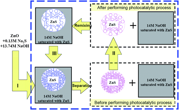 | ||
| Scheme 1 Illustration of the continuous recycling of a high-activity ZnS photocatalyst in three steps: step (I) preparation of the ZnS nano-structures via a synthetic strategy; step (II) during photocatalytic experiments, the ZnS microspheres with fine nano-structures were transformed into deactivated ZnS microspheres; step (III) recovery of ZnS microspheres using interwoven nano-sheets. | ||
As shown in Fig. 1a–c, the ZnS microspheres produced are composed of 20–30 nm interwoven nano-sheets, with the wurtzite ZnS (001) face as the exposed crystal face.8,9 These self-supported ZnS microspheres with diameters of 10–20 µm are effectively aggregation-free and maintain an excellent porous nano-structure. The structure has a relatively high Brunauer–Emmett–Teller (BET) surface area (124 m2 g−1), suggesting that the material could potentially be used for photocatalytic reactions with high efficiency. Dilute acetic acid was used to neutralize the photocarrier quenching center (OH− groups) on the crystal surfaces. After surface treatment, the ZnS nano-architectures exhibited a remarkable photocatalytic activity while maintaining their initial sizes and morphologies (Fig. S1 of the ESI†). As shown in Fig. 1d and Fig. S2 of the ESI,† the photocatalytic activity of the ZnS nano-architectures was comparable to that of commercial Degussa P25 titania during degradation of eosin B. The relatively high photocatalytic activity of the synthetic ZnS photocatalysts could also originate from the intrinsic properties of the materials listed as follows: (1) The polarization crystal structure facilitates the separation of the light-induced electrons and holes, and accelerates their diffusion to the surfaces of the materials. (2) The photocarrier generation efficiency of ZnS is high because it is a direct band-gap semiconductor (Fig. S7 and S8 of the ESI†).
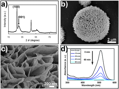 | ||
| Fig. 1 (a) XRD pattern, (b) and (c) scanning electron micrographs and (d) photocatalytic activity of ZnS microspheres with interwoven nano-sheets. The ZnS nano-architectures were produced via the ZnO + Na2S + NaOH initial states, which are thermodynamically equal to the ZnS + 14 M NaOH system. The sharp wurtzite (100) peak and broad (001) peak in the XRD pattern indicate that the dimensions of the ZnS ab-plane are on the micrometre scale, while the dimension in the c-direction is on the nanometre scale, thus nano-sheets with wurtzite (001) as the major exposure crystal face were formed. SEM observation shows these nano-sheets were further interwoven together to form microspheres as shown in (b) and (c). After surface acidification treatment with dilute acetic acid, the photocatalytic activity of ZnS was examined by degrading eosin B (eosin B: 5.0 × 10⁻⁵ M, 30 mL; ZnS nano-microspheres, 10 mg) under irradiation of 354 nm UV light from a 125 W mercury lamp. | ||
It is known that microstructured ZnS nano-catalysts are insufficiently stable when used in catalytic reactions. In our study, as revealed in Fig. 2a, after performing a photocatalytic function for six cycles, the photocatalytic activity of the ZnS nano-architectures reduced to 60%. At the same time, the ZnS microspheres lost most of their structural features (the interwoven nano-sheets). Instead, solid spherical structures were formed (Fig. 2c–d). Such structural changes were caused by the integrating growth of individual nano-sheets through an Ostwald ripening mechanism. As a result, the BET surface area decreased to 67.2 m2 g−1, indicating the decrease of the active sites for photocatalysis (Fig. S3 of the ESI†).
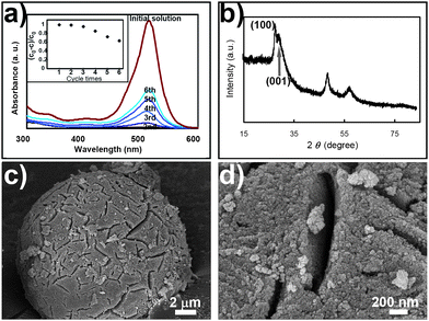 | ||
| Fig. 2 (a) Illustration of the cycle performance and morphological changes of the ZnS photocatalyst during the degradation of eosin B. With an increasing number of photocatalytic cycles, the amount of undegraded eosin B increased significantly within the same time interval (60 min), indicating that the photocatalytic activity of the ZnS photocatalyst declined. (b) After six cycles, the wurtzite (100) diffraction peaks are no longer sharp, indicating that the ZnS microspheres have lost their structural features (interwoven nano-sheets). (c) and (d) SEM observation confirmed that although the microspheric character of the ZnS photocatalyst still remained, the interwoven fine structures had disappeared completely. | ||
The recovery of the ZnS nano-architectures was carried out by placing the solid ZnS microspheres back into the thermodynamically stable environment of the ZnS nano-architectures,8,9 where the ZnS microspheres interwoven with nano-sheets were synthesized (Scheme 1, step III). As mentioned above, through experiments we have proved that the thermodynamically stable nanophase of ZnS in 14 M NaOH is ZnS microspheres composed of interwoven nano-sheets. The ZnS precursors of different sizes and morphologies transform into the final thermodynamically stable states spontaneously in this environment. Thus, in the end the solid ZnS microspheres transformed into the desired ZnS nano-architectures completely, as shown in Fig. 3a–c. Furthermore, with surface neutralization treatment, we found that the photocatalytic activity of the ZnS nano-architectures could be successfully recovered (Fig. 3d). Thus, we believe that by repeating step II and step III, the ZnS nano-photocatalyst can be recycled an infinite number of times.10
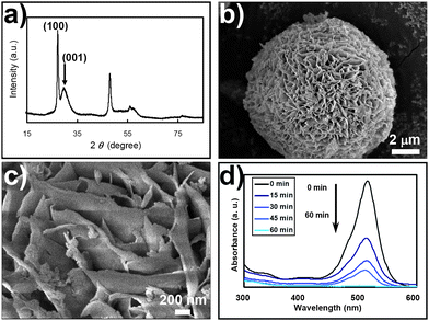 | ||
| Fig. 3 By putting the deactivated ZnS nano-catalyst back into its thermodynamically stable environment (14 M NaOH solution saturated with ZnS) and hydrothermally coarsening for 2 days, (a) the XRD pattern, and (b) and (c) the SEM observations, show the recovery of the interwoven fine structure of the ZnS photocatalyst. The photocatalytic activity of the material also recovered (d). | ||
It is well known that a variety of nano-sulfides exhibit fascinating catalytic activities. However, like ZnS, many nano-sulfides have a strong thermodynamic tendency to grow during catalytic processes (due to their relatively small lattice energy),6 limiting their real industrial applications. We believe that the proposed thermodynamic recycling strategy for nano-ZnS could potentially be applied to other sulfide-based catalytic materials, as long as thermodynamically stable conditions for the specific nano-materials can be found.11–13 Obviously, via a thermodynamic recycling strategy such as the one described here, the usage efficiency of nano-material increases while the amount of the nano-waste discharged into the environment reduces significantly.
In conclusion, we have shown a study of the photocatalysis, deactivation and regeneration of high-performance ZnS nano-architectures. The feasibility of “infinite recycling” of a nano-catalyst was demonstrated experimentally for the first time by adopting the thermodynamically stable environment of nano-ZnS. This strategy has the merits of high material use efficiency, is environmental friendly and is suitable for long-term usage.
Acknowledgements
This work was funded by the National Key Project of China for Basic Research (2010CB933501 and 2007CB815601), and the NNSF Outstanding Youth Fund (50625205) and (20803082, 20971123).Notes and references
- S. Yanagida, K. Mizumoto and C. J. Pac, J. Am. Chem. Soc., 1986, 108, 647–654 CrossRef CAS.
- J. S. Hu, L. L. Ren, Y. G. Guo, H. P. Liang, M. A. Cao, L. J. Wan and C. L. Bai, Angew. Chem., Int. Ed., 2005, 44, 1269–1273 CrossRef CAS.
- S. Kohtani, Y. Ohama, Y. Ohno, I. Tsuji, A. Kudo and R. Nakagaki, Chem. Lett., 2005, 34, 1056–1057 CrossRef CAS.
- H. Fujiwara, H. Hosokawa, K. Murakoshi, Y. Wada and S. Yanagida, Langmuir, 1998, 14, 5154–5159 CrossRef CAS.
- I. Tsuji, H. Kato, H. Kobayyashi and A. Kudo, J. Am. Chem. Soc., 2004, 126, 13406–13413 CrossRef CAS.
- Nano-sulfides are usually less stable than nano-oxides. The stability of nano-materials is determined by the total energy (Et), which is the sum of lattice energy (El) and surface energy (Es). When El is small, the proportion Es:Et is usually greater than when El is large. So materials with small lattice energies are less stable relative to their bulk counterparts, resulting in a stronger tendency to grow.
- Z. Lin, B. Gilbert, Q. L. Liu, G. Q. Ren and F. Huang, J. Am. Chem. Soc., 2006, 128, 6126–6131 CrossRef CAS.
- G. Q. Ren, Z. Lin, B. Gilbert, J. Zhang, F. Huang and J. K. Liang, Chem. Mater., 2008, 20, 2438–2443 CrossRef CAS.
- D. S. Li, Z. Lin, G. Q. Ren, J. Zhang, J. S. Zheng and F. Huang, Cryst. Growth Des., 2008, 8, 2324–2328 CrossRef CAS.
- The recovery of ZnS is carried out in a ZnS saturated solution, theoretically there is no mass loss of ZnS during this process.
- Recent investigation revealed that thermodynamically stable nano-systems could be found not only in ZnS materials, but also in other sulfides (Fig. S5 of the ESI †), oxides12 and fluorides.13.
- Z. Łodziana, N. Y. Topsøe and J. K. Nørskov, Nat. Mater., 2004, 3, 289–293 CrossRef CAS.
- T. Xie, S. A. Li, W. B. Wang, Q. Peng and Y. D. Li, Chem.–Eur. J., 2008, 14, 9730–9735 CrossRef CAS.
Footnote |
| † Electronic supplementary information (ESI) available: Experiment details: control experiments for photodegradation of eosin B; BET measurements of ZnS at different states; the thermodynamically stable nanophases of ZnS and CdS. See DOI: 10.1039/c0nr00171f |
| This journal is © The Royal Society of Chemistry 2010 |