Preparation, characterization and application of polyaniline nanospheres to biosensing
Chetna
Dhand
ab,
Maumita
Das
ab,
Gajjala
Sumana
a,
Avanish Kumar
Srivastava
a,
Manoj Kumar
Pandey
a,
Cheol Gi
Kim
c,
Monika
Datta
b and
Bansi Dhar
Malhotra
*ac
aDepartment of Science and Technology Centre on Biomolecular Electronics, National Physical Laboratory, CSIR, Dr K. S. Krishnan Marg, New Delhi 110012, India. E-mail: bansi.malhotra@gmail.com; Fax: +91-11-45609312; Tel: +91-11-45609152
bDepartment of Chemistry, University of Delhi, Delhi 110007, India
cCentre for NanoBioEngineering and Spintronics, Chungnam National University, Daejeon, 305-764, South Korea
First published on 9th March 2010
Abstract
Polyaniline nanospheres (PANI-NS) prepared by morphological transformation of micelle polymerized camphorsulfonic acid (CSA) doped polyaniline nanotubes (PANI-NT) in the presence of ethylene glycol (EG) have been characterized by X-ray diffraction, atomic force microscopy, transmission electron microscopy, scanning electron microscopy, Fourier transform infra-red and UV-Visible spectroscopy. A PANI-NS (60–80 nm) film deposited onto an indium-tin-oxide (ITO) coated glass plate by the solution casting method has been utilized for covalent immobilization of biomolecules (cholesterol oxidase (ChOx)) viaN-ethyl-N′-(3-dimethylaminopropyl) carbodiimide (EDC) and N-hydroxysuccinimide (NHS) chemistry for fabrication of a cholesterol biosensor. The ChOx/PANI-NS/ITO bioelectrode detects cholesterol in the concentration range of 25 to 500 mg dL−1 with sensitivity of 1.3 × 10⁻³ mA mg−1 dL and regression coefficient of 0.98. Further, this PANI-NS based bioelectrode shows fast response time (10 s), low Michaelis–Menten constant (2.5 mM) and shelf-life of 12 weeks. The spherical nanostructure observed in the final morphology of the PANI-NS film is attributed to hydrogen bonding interactions between PANI-NT and EG.
Introduction
Conducting polymers, because of their electronic conductivity, environmental stability, easy and controlled processability and biocompatibility, have emerged as promising materials for the development of sensors, electronic and optical devices.1–5 Among the various conducting polymers, polyaniline (PANI) is considered unique among the family of conjugated polymers due to its simple and reversible acid/base doping/dedoping chemistry enabling control over properties such as free volume,6 solubility,7 electrical conductivity,8 and optical activity.9 In recent years, nanostructured PANI (nanotubes/nanorods/nanospheres) has aroused much scientific interest since it combines the properties of low-dimensional organic conductors and high surface area materials and offers the possibility of enhanced performance wherever a large interfacial area between PANI and its environment is required. For example, in sensor applications, nanostructured PANI has been found to result in increased sensitivity and faster response time relative to its conventional bulk counterpart.10 The observed high sensitivity is attributed to extremely sensitive modulation of the electrical conductance/resistance of nanostructure brought about by changes in the electrostatic charges from surface adsorption of various molecules, leading to depletion or accumulation of the carriers in the “bulk” of the nanometre diameter structure.11Conventional chemical oxidative polymerization approaches to nanostructured PANI include the use of hard templates such as zeolite channels,12 track-etched polycarbonate13 and anodized alumina14 or soft templates such as surfactants,15 liquid crystals,16 thiolated cyclodextrins17 and polyacids etc.18 These templates are reported to be capable of directing growth of 1-D PANI nanostructures with diameters smaller than 100 nm. However, a post-synthetic treatment is required to remove these templates from the products to recover nanostructured PANI. Zhang et al. have reported a “non-template” approach to synthesize polyaniline nanotubes (PANI-NT) in the presence of camphor sulfonic acid (CSA) as a dopant. This method can be regarded as a self-assembly method19 because CSA/anilinium ion micelles act as templates in the formation of PANI-NT. Huang et al. have recently reported an interfacial polymerization method, effective to suppress secondary growth, wherein polymerization is performed in an immiscible organic/aqueous interface.10 This facile chemical route has been found to result in the production of PANI nanofibers having nearly uniform diameters between 30–50 nm with lengths varying from 500 nm to several micrometres under ambient conditions. Zhang et al. have described the formation of distinct nanofibers by seeding method.20 This is a conventional chemical oxidative polymerization of aniline in the presence of very small amounts of seed templates that can be biological (hexapeptide), inorganic (V2O5), or organic nanofibers (carbon nanotubes, PANI nanofibers). The shape of the seed has been found to control overall morphology of the nanostructure whereas its size does not seem to have any significant impact.
It has been proposed that the surrounding chemical environment may perhaps influence the morphology of the PANI nanostructure.21,22 In this context, Baker et al. have reported rapid reversible actuation of flash-welding PANI nanofiber mats in the presence of selected aqueous acids and bases.21 The actuation process pertains to the incorporation of the anionic dopants among the positively charged nanofibers resulting in p-doping of the emeraldine base form of PANI to form emeraldine salt on exposure to acids and this mechanism is reversible at basic pH. The mechanism of polymerization of the PANI nanostructure involves intra- and inter-chain interactions such as hydrogen bonding and π–π interactions that are affected by the nature of the solvent involved during this process. PANI with varied morphology can be prepared by controlling these interactions. Wu et al. have demonstrated reduction in the rate of polymerization of the PANI nanostructure by breaking intra- and inter-chain hydrogen bonding in the presence of phenol additives in the reaction mixture.22 Li et al. have explained the effect of the organic solvent on chirality of the PANI synthesized using poly(acrylic acid) (PAA) as template and CSA as dopant. It is observed that interaction between aniline and CSA (acid–base interaction) plays an important role in the formation of chiral PANI complexes. This acid–base interaction is expected to be weaker in the presence of an organic solvent, which results in a decreased value of the dielectric constant of the reaction medium. This reduced acid–base interaction is perhaps responsible and may contribute to destabilization of the PAA/aniline (Ani)/CSA complex, thus reducing nanocomposite chirality.23
There are number of methods available for the synthesis of various PANI nanostructures, however, the synthesis of nanospheres is still a challenging task mainly because the nanofibrillar morphology appears to be intrinsic to PANI. PANI nanospheres are particularly interesting for optoelectronics and sensors due to their large surface area. It is also important to note that the nanospheres can be effectively solvated due to their globular nature, which enhances the solubility in common solvents for structural characterization by spectroscopic techniques.24 In this context, it may be noted that only a few examples including the synthesis of PANI nanospheres, which include using templates such as polystyrene spheres25 and hydroxy alkyl cellulose26 and salicylic acid assisted polymerization27etc have been reported. Recently Anilkumar et al. have reported the PANI nanospheres based on a renewable resource based amphiphilic azobenzenesulfonic acid as a dopant via an interfacial route.28,29 Unlike its nanofibre counterparts, it has been found that the nanosphere formation is highly sensitive to the dopant/aniline and polymerization route, and in general, the synthesis and mechanism of nanosphere formation has not been understood.
In this manuscript, we report the morphological transformation of CSA doped PANI from nanotubes (NT) in the precursor to nanospheres (NS) in the presence of ethylene glycol (EG) as solvent. The PANI-NS film, deposited using the solution casting method at 100 °C under vacuum for 8 h onto indium-tin-oxide coated (ITO) glass plate, has been utilized for immobilization of cholesterol oxidase (ChOx) for application as a cholesterol biosensor.
Results and discussion
Fig. 1 shows the X-ray diffraction (XRD) pattern of CSA doped PANI-NT (i) and PANI-NS/ITO film (ii), that reveals three characteristic peaks (marked as 1, 2 and 3) centered at 2θ = 15°, 20.53°, and 25.28° associated with PANI. Pouget et al. have demonstrated that the peaks observed at 20.53° and 25.28° can be ascribed to periodicity parallel and perpendicular to the polymer chains, respectively.30 An additional peak seen at 2θ = 6.4° (marked as 4) indicates the organization of the PANI chains into nanotubes or lamellae and is found to be absent in the case of PANI nanospheres.31 The tubular morphology can be explained by the fact that the CSA/anilinium micelle during the polymerization acts as a pseudo-template for controlled growth of PANI in the form of nanotubes. The crystallite size of the PANI nanotubes and PANI nanospheres is found to be about 45 nm and 71.8 nm as estimated using Scherrer's formula (D = Kλ/Bcosθ). In the case of XRD of the PANI-NS/ITO film, clear diffraction patterns are not obtained since the films are too thin (180 nm) to carry out the XRD experiments and the substrate effect is also dominating (Fig. 1(ii)). Therefore, the selected area electron diffraction patterns (SADPs) of PANI nanotubes and nanospheres have also been recorded as shown in the insets of Fig. 4 (i) and 4 (iii).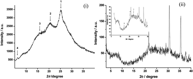 | ||
| Fig. 1 X-Ray diffraction pattern of (i) PANI-NT and (ii) PANI-NS/ITO film; Inset: Fig 1 (ii) shows the magnified view (intensity between 0 to 90 a. u.) of the XRD. | ||
In the FT-IR spectra of CSA-PANI in formic acid (FA, Fig. 2), the bands found at 1435 and 1528 cm−1 are attributed to C![[double bond, length as m-dash]](https://www.rsc.org/images/entities/char_e001.gif) C benzenoid and quinoid ring vibrations, respectively. The peaks seen at 1045 (NH+⋯SO3− interactions), 849 (S–O unsymmetric stretching) and 624 cm−1 (C–S stretching vibration), reveal the presence of CSA as dopant in PANI.32 Further, peaks found at 1360 and 3398 cm−1 show the presence of C–N bending and N–H stretching vibrations, respectively. The FT-IR spectra of PANI in EG (Fig. 2) reveals a blue shift in CC stretching vibrations and reduction in CC quinoid stretching, which may be due to the transformation of PANI from its emeraldine form to leucoemeraldine form. The bonding skeleton of both forms of PANI (see inset of Fig. 2) clearly reveals reduction in the quinoid moieties in the leucoemeraldine form which is also reflected by reduction of the peak height of the quinoid structure compared to its benzenoid counterpart in the spectra of CSA-PANI in EG. Further, in leucoemeraldine form of PANI, CC conjugation decreases, resulting in a blue shift of the CC stretching bands. This result is supported by the observed yellow color of PANI when dissolved in EG (see inset of Fig. 3). A further decrease and broadening in the N–H stretching frequencies from 3398 and 3505 cm−1 to 3145 and 3461 cm−1, respectively, and increase in the N–H bending vibrations from 1647 to 1663 cm−1 indicates the hydrogen bond formation between PANI and EG. Moreover, the absence of the peaks around 1045, 849 and 624 cm−1 indicates dedoping of PANI structure.
C benzenoid and quinoid ring vibrations, respectively. The peaks seen at 1045 (NH+⋯SO3− interactions), 849 (S–O unsymmetric stretching) and 624 cm−1 (C–S stretching vibration), reveal the presence of CSA as dopant in PANI.32 Further, peaks found at 1360 and 3398 cm−1 show the presence of C–N bending and N–H stretching vibrations, respectively. The FT-IR spectra of PANI in EG (Fig. 2) reveals a blue shift in CC stretching vibrations and reduction in CC quinoid stretching, which may be due to the transformation of PANI from its emeraldine form to leucoemeraldine form. The bonding skeleton of both forms of PANI (see inset of Fig. 2) clearly reveals reduction in the quinoid moieties in the leucoemeraldine form which is also reflected by reduction of the peak height of the quinoid structure compared to its benzenoid counterpart in the spectra of CSA-PANI in EG. Further, in leucoemeraldine form of PANI, CC conjugation decreases, resulting in a blue shift of the CC stretching bands. This result is supported by the observed yellow color of PANI when dissolved in EG (see inset of Fig. 3). A further decrease and broadening in the N–H stretching frequencies from 3398 and 3505 cm−1 to 3145 and 3461 cm−1, respectively, and increase in the N–H bending vibrations from 1647 to 1663 cm−1 indicates the hydrogen bond formation between PANI and EG. Moreover, the absence of the peaks around 1045, 849 and 624 cm−1 indicates dedoping of PANI structure.
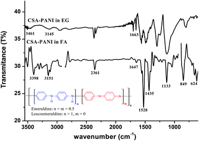 | ||
| Fig. 2 FT-IR spectra of CSA doped PANI in formic acid (FA) and ethylene glycol (EG). | ||
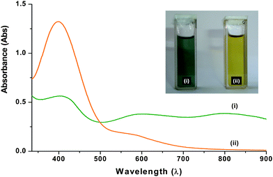 | ||
| Fig. 3 UV-Visible spectra of CSA doped PANI in (i) formic acid (FA) (ii) ethylene glycol (EG); inset shows visual observation of PANI colloidal suspension in (i) FA (ii) EG. | ||
Fig. 3 shows UV-Visible spectra of CSA doped PANI in FA (i, green in colour, 1 mg mL−1) and EG (ii, yellow in colour, 1 mg mL−1). The UV-Vis absorption spectrum of CSA doped PANI in formic acid (Fig. 3 (i)) shows three absorption bands at 402, 604, and 800 nm, respectively. The band at 402 nm is attributed to the polaron–π* transition in the emeraldine salt (ES). The localized polaron band around 800 nm indicates a compact coiled (tightly coiled chains) conformation of PANI and reveals the presence of PANI in its conducting form (ES).31 A small absorption band due to the exciton transition of the quinoid ring appears at 600 nm. In the absorption spectra of PANI in EG (Fig. 3 (ii)), we observed a blue shift in the peaks that corresponds to a polaron–π* transition (398 nm) and exciton transition of the quinoid ring (588 nm). Further, the disappearance of the band at 800 nm in UV-Vis spectra of PANI-NS may be attributed to the synergic effect of shortening of polymer chains and transformation of PANI from its emeraldine form to leucoemeraldine form due to the hydrogen bonding interaction between PANI in EG and is also supported by the FT-IR spectra (Fig. 2).33
Electron microscopy observations of CSA doped PANI nanostructures using HR-TEM have been carried out both in FA and EG to reveal the effect of solvent on its morphology. The TEM micrograph of CSA-PANI in FA (Fig. 4 (i)) shows a well-defined nanotube structure with diameter ranging from 40–50 nm which supports the result obtained by XRD (Fig. 1 (i), particle size ∼45 nm) and SEM analysis (Fig. 4 (vi)), respectively. These nanotube morphologies are elongated with smooth surfaces and a strained contrast develops at some regions along transverse directions of the tube. The transformation of the PANI nanotube to PANI nanospheres in EG with diameter ranging from 60 to 80 nm is clearly illustrated in the TEM micrograph (Fig. 4 (ii), (iii)). Selected area electron diffraction patterns (SADPs) recorded from nanotubes and nanospheres are displayed as insets in Fig. 4 (i) and 4 (iii), respectively. The Debye rings 1, 2, 3 correspond to the peaks 1, 2 and 3 in the XRD (Fig. 1). However, the Debye ring 4 in case of nanotubes (SADP in Fig. 4 (i)) appears as a diffused circle in the case of nanospheres (SADP in Fig. 4 (iii). The Debye ring 4 corresponds to peak 4 in XRD (Fig. 1) which is due to an inter-lamellae (or inter-planar) separation of 1.379 nm (2θ = 6.4°). These observations are in agreement with the previous results that reveal a peak at around 2θ = 6.4° emerges due to short range ordering in case of tubular-morphology.34 Moreover, the diffused circle (marked as 4, Fig. 4 (iii)) infers the absence of ordered-lamellae structure in nanospheres. This morphological change in the PANI nanotube structure can be attributed to hydrogen bonding interactions between EG and PANI that result in generation of energy (solvation energy), which in turn helps to break the strained region along the length of the tubes and gives PANI nanospheres (Scheme 1). Further, the retention of spherical morphology of PANI after film formation by the solution casting method has been observed in the AFM micrographs. The 2-D micrograph of the PANI-NS film (Fig. 4 (iv)) reveals its dense, uniform and homogenous morphology having nanospheres with diameters ranging from 55 to 80 nm with surface roughness (Ra) of 4.87 nm. Further, the 3D micrograph (Fig. 4 (v)) of PANI-NS reveals nano-porous morphology of the film.
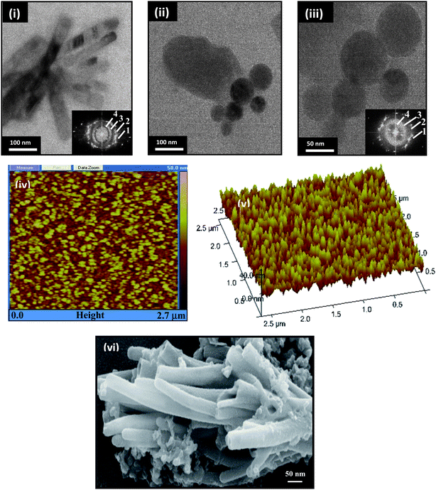 | ||
| Fig. 4 Morphological characterization of polyaniline nanostructures; HR-TEM images of (i) PANI-NT in FA, (ii–iii) PANI-NS in EG, AFM images and SEM micrograph of PANI-NT of (iv) 2-D view (v) 3-D view of PANI-NS/ITO electrode. SADPs from nanotubes and nanospheres are displayed as insets in (i) and (iii). | ||
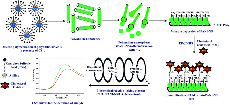 | ||
| Scheme 1 Pictorial representation of the morphological transformation of the PANI-NT to PANI-NS, immobilization of ChOx and the biochemical reaction involved in cholesterol sensing. | ||
Contact angle (CA) measurements have been carried out to investigate the immobilization of ChOx using the Sessile drop method. The change in the value of CA reveals the hydrophobic/hydrophilic character of the surface, which in turn can be related to modification of the surface with biomolecules. Fig. 5 (i) and (ii) shows the variation of CA of PANI-NS/ITO and ChOx/PANI-NS/ITO, respectively. The decrease in the value of CA from 58.76° to 9.93° after ChOx immobilization indicates immobilization of ChOx onto the PANI-NS/ITO surface due to the presence of hydrophilic groups in the ChOx molecules.
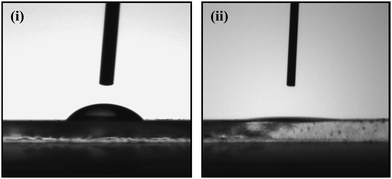 | ||
| Fig. 5 Contact angle measurement of (i) PANI-NS/ITO LB film electrode and (ii) ChOx/PANI-NS/ITO film bioelectrode. | ||
Fig. 6 (A) shows the CV obtained for PANI-NS/ITO and ChOx/PANI-NS/ITO electrodes in the potential range of −0.3 to 0.7 V at a scan rate of 50 mV s−1. The decrease in the anodic current obtained for the ChOx/PANI-NS/ITO (0.285 mA, curve (ii)) compared to that of PANI-NS/ITO electrode (0.377 mA, curve (i)) indicates the hindrance caused by the macromolecular structure of the enzyme indicating ChOx immobilization. Fig. 6 (B) shows a cyclic voltammogram (CV) of the PANI-NS/ITO electrode recorded at different scan rates (10–100 mV s−1). It can be seen that as we move towards the higher scan rate, the anodic potential shifts more towards the positive potential and the cathodic peak potential shifts in the reverse direction. Besides this, the redox peak currents show linear behavior with square root of scan rate ( ), (see inset of Fig. 6 (B)), revealing a diffusion controlled electron-transfer process and follow eqn (1) and (2).
| Ia (mA) = 0.167 (mA) + 0.055 (mA mV−1 s) * scan rate (mV s−1), R = 0.999 | (1) |
| Ic (mA) = 0.084 (mA) + 0.037 (mA mV−1 s) * scan rate (mV s−1), R = 0.997 | (2) |
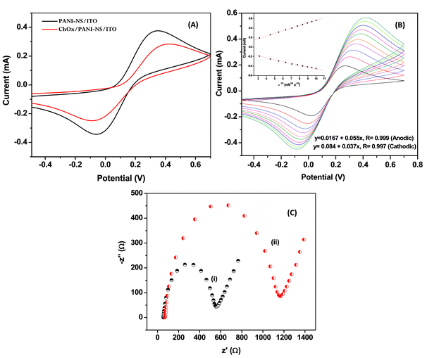 | ||
| Fig. 6 (A) Cyclic voltammogram of fabricated electrodes; (B) CV of PANI-NS/ITO electrode in PBS at a scan rate from 10 mV s−1 to 100 mV s−1; (C) electrochemical impedance spectra of (i) PANI-NS/ITO (ii) ChOx/PANI-NS/ITO bioelectrode in PBS (50 mM, pH 7.4, 0.9% NaCl) solution. | ||
The peak-to-peak separation potential (ΔE = Ea − Ec) increases as a function of scan rate, indicating facile charge transfer kinetics in the 10 mV s−1 to 100 mV s−1 range of scan rates according to eqn (3):
| ΔE (V) = 0.0027 (V) + 0.26 (s) * scan rate (mV s−1), R = 0.98 | (3) |
EIS provides an effective method to probe electronic features of surface-modified electrodes. Fig. 6 (C) shows Nyquist plots obtained for PANI-NS/ITO, ChOx/PANI-NS/ITO electrodes, respectively in the frequency range of 0.01–105 Hz. Nyquist diameter (real axis value at lower frequency intercept) indicates the value of charge transfer resistance (RCT) i.e. hindrance provided by the electrode material to transfer charge from solution to the electrode that can be correlated with the modification of the surface. It can be seen that the RCT value obtained for the ChOx/PANI-NS/ITO electrode (curve (ii), 1.17 KΩ) obtained is higher than that of the PANI-NS/ITO electrode (curve (i), 0.54 KΩ) and can be attributed to the insulating nature of ChOx that inhibits permeability of [Fe(CN)6]3−/4− to the electrode surface.
Biosensing studies on the ChOx/PANI-NS/ITO bioelectrode have been carried out using linear sweep voltammetry (LSV, Fig. 7 (A)). An anodic peak is observed around 0.36 V in LSV. It can be seen that the anodic current increases continuously with cholesterol concentration. The amperometric current corresponding to this potential for the ChOx/PANI-NS/ITO bioelectrode has been plotted (Fig. 7 (B)) and the results show that this bioelectrode can be used to estimate cholesterol in the range of 25 to 500 mg dL−1 with a detection limit of 67 mg dL−1 and response time of 10 s. The anodic peak seen around 0.36 V corresponds to the oxidation of PANI present in the matrix, and its increase with increased cholesterol concentration suggests that ChOx gets electrically contacted by PANI–NS modified ITO electrode. It may be noted that no peak is observed relating to the oxidation of H2O2 in the range of 0.5 to 0.7 V indicating that there is direct transfer of electrons from the reduced ChOx enzyme to the PANI–NS matrix during the biochemical reaction (Scheme 1). The results of experiments carried out in triplicate sets reveal reproducibility of the system within 5%. Further, this PANI-NS based bioelectrode shows high sensitivity (1.3 × 10⁻³ mA mg−1 dL), regression coefficient (0.98), reproducibility (10 times), and shelf life up to 12 weeks.
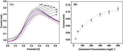 | ||
| Fig. 7 (A) LSV recorded for ChOx/PANI-NS/ITO bioelectrode as a function of concentration of cholesterol; 0 mg dL−1 (i) 25 mg dL−1 (ii), 50 mg dL−1 (iii), 100 mg dL−1 (iv), 200 mg dL−1 (v), and 300 mg dL−1 (vi), 400 mg dL−1 (vii) and 500 mg dL−1 (viii) in PBS (50 mM, pH 7.4, 0.9% NaCl) solution; (B) calibration plots derived from the LSV at 0.36 V as a function of cholesterol concentration (25 to 500 mg dL−1). | ||
The value of the apparent Michaelis–Menten constant (Kappm) estimated using the Hanes plot has been found to be 97 mg dL−1 (2.5 mM). The lower value suggests that the PANI-NS matrix facilitates enzymatic reaction and helps the immobilized enzyme to achieve better conformation for faster enzymatic reaction resulting in enhanced enzymatic activity. The response of the ChOx/PANI-NS/ITO bioelectrode has been investigated at different pH and temperatures (data not shown). The results reveal that this bioelectrode shows maximum activity around pH 7.4 at 28 °C. A brief comparison of cholesterol sensing with different PANI's is given in Table 1.
| No. | Matrix | Linearity (mg dL−1) | Sensitivity | Response time | Shelf life | Reference |
|---|---|---|---|---|---|---|
| 1. | PANI Langmuir Blodgett film | 25–400 | 88.9 nA mg−1 dL | — | 10 weeks | 35 |
| 2. | Electrochemically deposited PANI | 100–400 | 0.042 μA mg−1 dL | 240 s | 6 weeks | 36 |
| 3. | Electrophoretically deposited nano-structured PANI | 25–400 | 7.76 × 10⁻⁵ Abs mg−1dL | 6 min | 11 weeks | 37 |
| 4. | Electrochemically deposited bulk PANI | 50–500 | 7.5 × 10⁻⁴ nA mg−1 dL | 40 s | 45 days | 38 |
| 5. | Electrochemically prepared PANI matrix | 1.84–18.4 | — | — | 11 days | 39 |
| 6. | Chemically fabricated PANI nanospheres | 25–500 | 1.3 × 10⁻³ mA mg−1dL | 10 s | 12 weeks | Present work |
Conclusions
Polyaniline nanotubes have been prepared using APS as oxidant and CSA as dopant by micellar polymerization. Further, the observed morphological transformation of CSA doped PANI from its nanotubular form to nanospheres in real as well as reciprocal space in the presence of ethylene glycol as solvent has been analyzed using XRD, TEM, SEM and AFM techniques. This change in the shape of PANI nanostructure is attributed to strong affinity of the ethylene glycol to form hydrogen bonds with the –NH2 moieties of PANI. Besides this, homogenous and uniform films of PANI nanospheres (PANI-NS) have been fabricated on ITO coated glass plate via solution casting of PANI-EG solution and the films have been utilized to fabricate a ChOx/PANI-NS/ITO bioelectrode that can be used to detect cholesterol in the physiological range of 25 to 500 mg dL−1 for cholesterol with high sensitivity (1.3 × 10⁻³ mA mg−1 dL) and fast response time (10 s). It should be interesting to ascertain the effect of other PANI nanostructures including PANI nanotubes, PANI nanorods etc. on the cholesterol sensing characteristics. Besides this, attempts should be made to utilize such nanostructured PANI platforms including PANI nanospheres for the development of other biosensors for estimation of lipoprotein, triglycerides, glucose and urea etc.Experimental section
Materials
ChOx (E.C. 1.1.3.6, from Pseudomonas fluorescens, specific activity: 24 U mg−1), N-hydroxysuccinimide (NHS), N-ethyl-N-(3-dimethylaminopropyl carbodiimide) (EDC), CSA (anionic surfactant) and ammonium peroxysulfate (APS, oxidant) have been purchased from Sigma Aldrich. Aniline (C6H5NH2) is distilled prior to polymerization. All other chemicals used are of analytical grade and have been used without purification. Deionized water (resistance: 18.2 MΩ) from the Millipore water purification system has been used in the preparation of aqueous solutions. Pre-cleaned ITO coated glass plates (sheet resistance: 30 Ω cm−1) have been used as substrates for the deposition of PANI.Synthesis of CSA doped polyaniline nanotubes (PANI-NT)
PANI-NT has been synthesized by oxidative miceller polymerization using CSA as dopant and APS as oxidant.19 Polymerization of PANI-NT is carried out by adding aniline (0.2 M) and CSA (0.2 M) in distilled water (10 mL), wherein both the components react to form CSA/anilinium micelles. This solution is cooled in an ice bath prior to polymerization. Then a cold aqueous solution of APS (2 M, 5 mL) is added to the CSA/anilinium salt solution and the mixture is allowed to react for 15 h in the ice bath. Finally, the obtained product is filtered and washed with distilled water and methanol several times followed by drying in vacuum at room temperature for 24 h.Deposition of CSA doped polyaniline nanospheres (PANI-NS) film
CSA doped PANI-NS film has been deposited onto ITO coated glass plate by solution casting using CSA doped PANI dispersion. The dispersion has been prepared by dissolving PANI-NT in EG (1 mg mL−1) wherein the interaction of EG with PANI-NT results in the formation of PANI-NS. Further, this PANI-NS dispersion (50 μL) is uniformly spread onto pre-cleaned ITO (1 cm2) followed by solvent evaporation at 100 °C under vacuum for 8 h.Immobilization of ChOx onto PANI-NS/ITO electrode
ChOx (15μL) is covalently immobilized onto a PANI-NS/ITO electrode via amide bond formation between –NH or –NH2 group of PANI with –COOH group of ChOx using EDC (0.4 M) as the coupling agent and NHS (0.1 M) as activator (Scheme 1).37 The bioelectrode (ChOx/PANI-NS/ITO) thus fabricated is washed thoroughly with phosphate buffer saline (PBS, 50 mM, pH 7.4) containing NaCl (0.9%) and Tween 20 (0.05%) to wash out any unbound enzyme and is stored at 4 °C when not in use.Instrumentation
The morphologies of CSA doped PANI have been examined by atomic force microscopy (AFM, Nanoscope5, Veeco instrument Ltd.), Scanning electron microscopy (SEM, LEO-40) and high resolution transmission electron microscopy (HR-TEM, Tecnai G2 F30 STWIN, 300 kV). The absorption spectra of PANI dissolved in formic acid (FA) and EG have been recorded with UV-Visible spectrophotometer (Model 2200DPCV, Phoenix). The molecular structure of the PANI has been identified by X-ray diffraction (XRD, Miniflex II Desktop (Riguke Company)) and Fourier transform infra-red (FT-IR) spectroscopy using Perkin–Elmer Spectrophotometer (model “Spectrum BX” using ATR accessory). Electrochemical investigations of PANI-NS/ITO and ChOx/PANI-NS/ITO bioelectrode have been carried out using an Autolab Potentiostat/Galvanostat (Eco Chemie, Netherlands) in a conventional three-electrode electrochemical cell consisting of Ag/AgCl as reference electrode and platinum foil as the counter electrode. Cyclic voltammetry (CV) and linear sweep voltammetry (LSV) studies have been carried out in PBS solution. Electrochemical impedance spectroscopy (EIS) studies have been performed in the frequency range, 0.01–105 Hz with amplitude of 5 mV in PBS containing [Fe(CN)6]3−/4− (5 mM) as a redox probe.Acknowledgements
We thank Dr R. C. Budhani, Director, National Physical Laboratory, New Delhi, for providing facilities. Chetna Dhand and Maumita Das are thankful to the Council of Scientific and Industrial Research (CSIR), India, for award of Senior Research Fellowship. The authors thank Dr S. K. Dhawan, Mr. S. B. Samanta and Mr. Sandeep Singh for providing the required facilities of vacuum oven and AFM analysis, respectively. We acknowledge the financial support received from the Department of Science and Technology (DST), the Department of Biotechnology, Govt. of India (DBT/GAP070832) and the Ministry of Education, Science and Technology (R32-20026) of Korea.References
- J. Janata and M. Josowicz, Nat. Mater., 2002, 2, 19.
- J. Haung, S. Virji, B. H. Weiller and R. B. Kaner, Chem.–Eur. J., 2004, 10, 1314 CrossRef CAS.
- J. Liu, Y. Lin, L. Liang, J. A. Voigt, D. L. Huber, Z. R. Tian, E. Coker, B. Mckenzie and M. Mcdermott, Chem.–Eur. J., 2003, 9, 604 CrossRef CAS.
- C. Dhand, S. K. Arya, S. P. Singh, B. P. Singh, M. Datta and B. D. Malhotra, Carbon, 2008, 46, 1727 CrossRef CAS.
- C. Dhand, P. R. Solanki, K. N. Sood, M. Datta and B. D. Malhotra, Electrochem. Commun., 2009, 11, 1482 CrossRef CAS.
- M. R. Anderson, B. R. Mattes, H. Reiss and R. B. Kaner, Science, 1991, 252, 1412 CrossRef CAS.
- Y. Cao, P. Smith and A. J. Heeger, Synth. Met., 1993, 57, 3514 CrossRef CAS.
- J. C. Chiang and A. G. MacDiarmid, Synth. Met., 1986, 13, 193 CrossRef CAS.
- Y. N. Xia, J. M. Wiesinger, A. G. MacDiarmid and A. J. Epstein, Chem. Mater., 1995, 7, 443 CrossRef CAS.
- J. Huang, S. Virji, B. H. Weiller and R. B. Kaner, J. Am. Chem. Soc., 2003, 125, 314 CrossRef CAS.
- K. Ramanathan, M. A. Bangar, M. Yun, W. Chen, N. V. Myung and A. Mulchandani, J. Am. Chem. Soc., 2005, 127, 496 CrossRef CAS.
- C. G. Wu and T. Bein, Science, 1994, 264, 1757 CrossRef CAS.
- C. R. Martin, Chem. Mater., 1996, 8, 1739 CrossRef CAS.
- C. W. Wang, Z. Wang, M. K. Li and H. L. Li, Chem. Phys. Lett., 2001, 341, 431 CrossRef CAS.
- J. C. Michaelson and A. J. McEvoy, J. Chem. Soc., Chem. Commun., 1994, 79 RSC.
- L. M. Huang, Z. B. Wang, H. T. Wang, X. L. Cheng, A. Mitra and Y. X. Yan, J. Mater. Chem., 2002, 12, 388 RSC.
- S. J. Choi and S. M. Park, Adv. Mater., 2000, 12, 1547 CrossRef CAS.
- J. M. Liu and S. C. Yang, J. Chem. Soc., Chem. Commun., 1991, 1529 RSC.
- L. Zhang and M. Wan, Nanotechnology, 2002, 13, 750 CrossRef CAS.
- X. Zhang, W. J. Goux and S. K. Manohar, J. Am. Chem. Soc., 2004, 126, 4502 CrossRef CAS.
- C. O. Baker, B. Shedd, P. C. Innis, P. G. Whitten, G. M. Spinks, G. G. Wallace and R. B. Kaner, Adv. Mater., 2008, 20, 155 CrossRef CAS.
- C. G. Wu, C. H. Chiang and U. S. Jeng, J. Phys. Chem. B, 2008, 112, 6772 CrossRef CAS.
- W. Li, P. A. McCarthy, D. Liu, J. Huang, S. C. Yang and H. L. Wang, Macromolecules, 2002, 35, 9975 CrossRef CAS.
- E. Jin, X. Wang, N. Liu and W. Zhang, Mater. Lett., 2007, 61, 4959 CrossRef CAS.
- C. Barthet, S. P. Armes, S. F. Lascelles, S. Y. Luk and H. M. E. Stanley, Langmuir, 1998, 14, 2032 CrossRef.
- A. Riede, M. Helmstedt, V. Riede and J. Stejskal, Langmuir, 1998, 14, 6767 CrossRef CAS.
- L. Zhang and M. X. Wan, Adv. Funct. Mater., 2003, 13, 815 CrossRef CAS.
- P. Anilkumar and M. Jayakannan, J. Phys. Chem. C, 2007, 111, 3591 CrossRef CAS.
- P. Anilkumar and M. Jayakannan, Macromolecules, 2007, 40, 7311 CrossRef CAS.
- J. P. Pouget, M. E. Jozefowicz, A. J. Epstein, X. Tang and A. G. MacDiarmid, Macromolecules, 1991, 24, 779 CrossRef CAS.
- R. Sainz, W. R. Small, N. A. Young, C. Valle's, A. M. Benito, W. K. Maser and M. H. Panhuis, Macromolecules, 2006, 39, 7324 CrossRef CAS.
- P. Anilkumar and M. Jayakannan, Langmuir, 2006, 22, 5952 CrossRef CAS.
- C. C. Han and H. Y. Chen, Macromolecules, 2007, 40, 8969 CrossRef CAS.
- Y. Yang and M. Wan, J. Mater. Chem., 2002, 12, 897 RSC.
- Z. Matharu, G. Sumana, S. K. Arya, S. P. Singh, V. Gupta and B. D. Malhotra, Langmuir, 2007, 23, 13188 CrossRef CAS.
- S. Singh, P. R. Solanki, M. K. Pandey and B. D. Malhotra, Sens. Actuators, B, 2006, 115, 534 CrossRef.
- C. Dhand, S. P. Singh, S. K. Arya, M. Datta and B. D. Malhotra, Anal. Chim. Acta, 2007, 602, 244 CrossRef CAS.
- S. Singh, P. R. Solanki, M. K. Pandey and B. D. Malhotra, Anal. Chim. Acta, 2006, 568, 126 CrossRef CAS.
- S. Dong and X. Chen, Rev. Mol. Biotechnol., 2002, 82, 303–323 CrossRef CAS.
| This journal is © The Royal Society of Chemistry 2010 |